After oplev diagonalization of SRM TM (klog #13731), we balanced the coil gains.
Method:
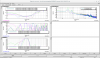
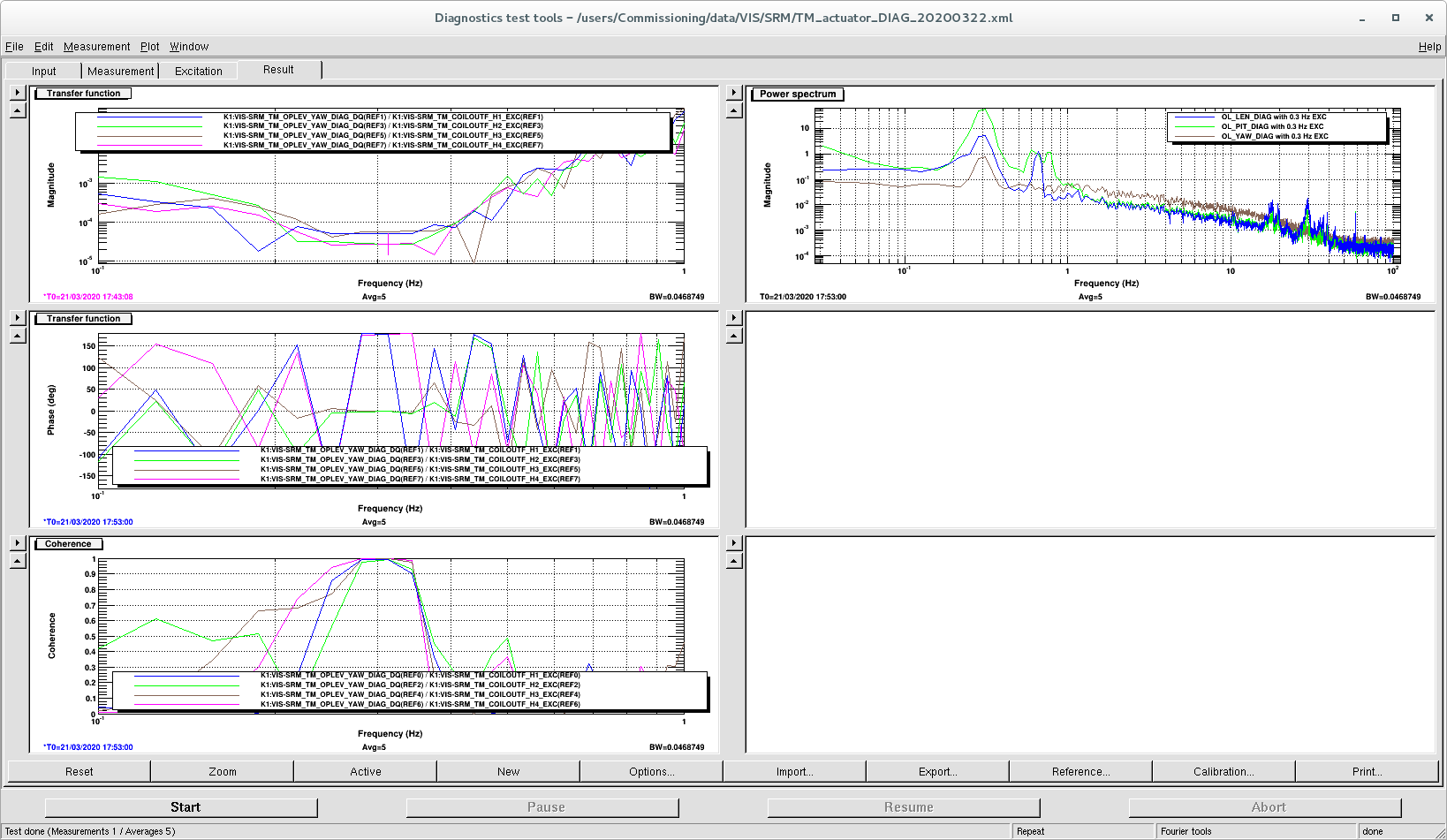
I follwed the method by Ushiba-san (see klog #13614 and following comments). Measured the TF from K1:VIS-SRM_TM_COILOUTF_H*_EXC to K1:VIS-SRM_TM_OPLEV_YAW_DIAG_DQ at 0.3 Hz, exciting at the amplitude of 5000 counts. Attached figure shows the transfer functions and coherence.
The balanced result is H1:H2:H3:H4=0.54900738:-1.:0.48986981:-1.03231169.
I also changed the EUL2OSEM matrix from
L P Y
H1 0.245 1.00 -1.00
H2 0.255 -1.00 -1.00
H3 0.255 -1.00 1.00
H4 0.245 1.00 1.00
to
H1 0.25 1.00 -1.00
H2 0.25 -1.00 -1.00
H3 0.25 -1.00 1.00
H4 0.25 1.00 1.00
DTT configuration file lives in /users/Commissioning/data/VIS/SRM/TM_actuator_DIAG_20200322.xml
Also related script at /users/Commissioning/data/VIS/SRM/TMcoilbalance.py
Discussion:
H1 and H3 had twice the efficiency than H2 and H4. Is it reasonable?
H1 and H3 are diagonal actuators, so this don't affect much to controls.
I made a script to balance the coils with COILOUTF gains so that each coil creates the same amount of oplev yaw signal at given frequency.
It balances the coils within roughly 8 minutes with default setting.
The script lives in /users/Commissioning/scripts/diagonalization/balanceCOILOUTF.py.
I applied it for SRM.
It should also work for SR2, SR3, and BS but I haven't tested it yet.
It should also work for PRs (LOCKIN module is hidden from the MEDM screen, but they seem to have those in the model).
It does not work for ITMs and ETMs. They don't have LOCKIN modules, and their coils are arranged differently (+ instead of x).
I noticed that the signs of SRM coils are strange.
See this figure from klog #13732. H1_EXC to YAW_DIAG and H2_EXC to YAW_DIAG should have the same sign, but that's not the case.
How come??
Result:
For SRM it was updated with the measurement which has the standard deviation of ~5% with 10 seconds of integration time, 10 averages for each coil.
Demodulation amplitudes (mean): [-324.91433716 277.059198 327.8017395 -284.50724487]
Demodulation amplitudes (stdev in %): [-3.95467175 2.43225212 4.61708457 -3.49204953]
Current COILOUTF gain: [ 0.54900738 -1. 0.48986981 -1.03231169]
New COILOUTF gain: [ 0.46814661 -1. 0.41403971 -1.00528705]
I kept the signs the same as previous ones.
Usage:
usage: balanceCOILOUTF.py [-h] [-f FREQ] [-a AMP] [-d DURATION] [-r REPEAT] OPTIC
Balance the coils with COILOUTF gains by shaking each coil
e.g. balanceCOILOUTF.py SRM
balanceCOILOUTF.py SR2 -f 0.3 -a 5000 -d 10 -r 10
positional arguments:
OPTIC Optic you want to balance the coils (e.g. SRM)
optional arguments:
-h, --help show this help message and exit
-f FREQ Modulation frequency [default=0.3 Hz]
-a AMP Modulation amplitude [default=5000cnts]
-d DURATION Duration of each measurement [default=10sec]
-r REPEAT Number of averages [default=10]
Method:
1. Shakes the mirror by injecting excitation from VIS-%s_TM_LKIN_Y_OSC to each coil.
2. Opens ndscope to monitor coil output channels and oplev pitch/yaw signal.
3. Demodulate VIS-%s_TM_OPLEV_YAW_DIAG with VIS-%s_TM_COILOUTF_H%d_IN1.
4. Repeat the measurement by given number of averages, and take the average.
5. Calculate the gains by taking the ratio with H2.
6. If the user says yes, the script updates the COILOUTF gains.
7. If you noticed some mistakes, Ctrl-C will safely shut down the modulation.
I noticed that the signs of SRM coils are strange.
See this figure from klog #13732. H1_EXC to YAW_DIAG and H2_EXC to YAW_DIAG should have the same sign, but that's not the case.
How come??
It is possible that the coils are placed in alternate polarity. Fabian should know the answer.
I noticed that the signs of SRM coils are strange.
See this figure from klog #13732. H1_EXC to YAW_DIAG and H2_EXC to YAW_DIAG should have the same sign, but that's not the case.
How come??
The results shown look unsual. The TF from each coil actuated separately to yaw has the following features
- The ones from H1 and H2 to yaw have opposite sign as Michimura-kun pointed out; we were expecting them to have the same phase.
- The ones from H4 and H3 to yaw have opposite sign also and we were expectig them to have the same phase.
The polarity of magnets (entry 5771) seems to be consistent with the signs in the COIL OUTPUT FILTERS:
- H1: north, +
- H2: south, -
- H3: north, +
- H4: south, -
This arragement means that applying actuation in the channels used by Michumura-kun (K1:VIS-SRM_TM_COILOUTF_H*_EXC) should not see any effect of the different polatities of the magnets.
More checking would be necessary in order to find out.
SRM coil signs were fine after all!
Previous coil balancing was done with TILT QPD out of range and wrong. This also created the sign mistake.
I have updated the COILOUTF gains with TILT QPD in the range.
What I did:
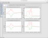
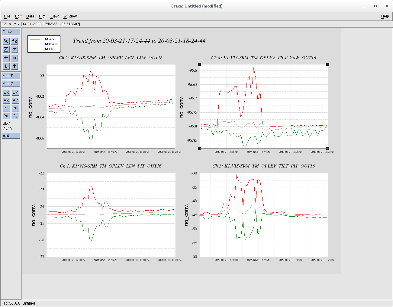
1. Checked the polarity of SRM TM coils by injecting amplitude of 5000cnts 0.1 Hz signal from K1:VIS-SRM_TM_LKIN_Y_EXC, and changing the signs of K1:VIS-SRM_TM_LKIN2OSEM_*_2 to change the polarity, when TILT QPDs are within the range (K1:VIS-SRM_TM_OPLEV_TILT_(PIT|YAW)_OUT within +/- 100; Note that LEN QPD in YAW was out of range right now). Below are the result showing the peak-to-peak values seen in oplev signals for each polarization. They look as expected. Very well!
H1 + + - + + + + -
H2 + - - - + + - +
H3 + - + + + - + +
H4 + + + - - + + +
LEN_DIAG +10 0 0 -8 3 +8 +4 -8 [um]
PIT_DIAG 0 +100 +50 0 -80 +40 +80 -40 [urad]
YAW_DIAG 0 +20 +40 0 -40 0 +20 0 [urad]
2. Checked the polarity when SRM was misaglined (When people were working with PRFPMI). The polarity looked completely different, and [H1,H2,H3,H4]=[+,-,-,+] gave the most amplitude in LEN_DIAG.
3. Checked if QPDs where in the range when I did the balancing in klog #13732, Mar 21, 2020 around 17:50 UTC. See attached. TILT_YAW is out of range! This and the above table explains why H1 and H4 had the same sign to YAW_DIAG signal. SRM had to be heavily misaligned since SRM motion might create some noise to PRFPMI.
4. Ran balanceCOILOUTF.py script with TILT QPDs in the range (note that LEN_YAW was out of range). Below are the result. Measurement standard deviation for 10 averages were within 1%. Way better than the previous measurent. New COILOUTF gains also look more reasonable.
Demodulation amplitudes (mean):    [ -6430.72324219 -15681.38027344   6654.85439453  17052.27539062]

	Demodulation amplitudes (stdev in %):    [-0.94481054 -0.38254446  0.92357048  0.39189616]

	Current COILOUTF gain:    [ 0.468      -1.          0.414      -1.00528705]

	New COILOUTF gain: [ 1.14122249 -1.          0.97554222 -0.92446833]
Moral of the story:
- Don't work on the suspensions when they are misaligned.
- Don't work on the suspensions when people are working on the main interferometer.
Next:
- Center the oplev QPDs for SRs with good alignment.
- Redo the coil balancing for SRs (with /users/Commissioning/scripts/diagonalization/balanceCOILOUTF.py).
- Redo the oplev diagonalization if necessary.
After QPD centering campaign of PRM, PR2, PR3, SR2 and SRM (BS and SR3 were already quite centered), I ran coil balancing script for all the SRs and COILOUTF gains were updated.
Result:
See below. As you can see, updated COILOUTF gains are similar to the new ones including the signs, and looks reasonable.
===== Result of SRM TM COILOUTF balancing =====
Measured on local time from 2020/03/23, 08:42:55 for 526 seconds
OPLEV_TILT_PIT_INMON= -0.06, OPLEV_TILT_YAW_INMON= 0.01, OPLEV_TILT_SUM_OUTMON= 2815.00
Modulation frequency and amplitude, measurement time, number of averages: 0.3 Hz, 5000 cnts, t=10 sec, Nave=10
Demodulation amplitudes (mean): [-24831.11757812 -24534.71523437 24715.49570313 24535.20996094]
Demodulation amplitudes (stdev in %): [-0.47989786 -0.32132244 0.45121478 0.36093483]
Current COILOUTF gain: [ 1.14122249 -1. 0.97554222 -0.92446833]
New proposed COILOUTF gain: [ 1.12760002 -1. 0.96840666 -0.92444969]
=====
===== Result of SR2 TM COILOUTF balancing =====
Measured on local time from 2020/03/23, 08:45:24 for 527 seconds
OPLEV_TILT_PIT_INMON= -0.00, OPLEV_TILT_YAW_INMON= 0.01, OPLEV_TILT_SUM_OUTMON= 6826.57
Modulation frequency and amplitude, measurement time, number of averages: 0.3 Hz, 5000 cnts, t=10 sec, Nave=10
Demodulation amplitudes (mean): [-23857.80507812 -23242.00195312 23967.53574219 24606.60820313]
Demodulation amplitudes (stdev in %): [-0.56129216 -1.30421421 0.69170405 1.60729312]
Current COILOUTF gain: [ 1. -1. 1. -1.]
New proposed COILOUTF gain: [ 0.97418861 -1. 0.96972848 -0.9445431 ]
=====
===== Result of SR3 TM COILOUTF balancing =====
Measured on local time from 2020/03/23, 08:48:05 for 523 seconds
OPLEV_TILT_PIT_INMON= 0.07, OPLEV_TILT_YAW_INMON= 0.09, OPLEV_TILT_SUM_OUTMON= 7309.22
Modulation frequency and amplitude, measurement time, number of averages: 0.3 Hz, 5000 cnts, t=10 sec, Nave=10
Demodulation amplitudes (mean): [-18417.67856445 -20028.0203125 21280.990625 20915.75878906]
Demodulation amplitudes (stdev in %): [-20.74940548 -0.74654131 1.12051786 0.54908598]
Current COILOUTF gain: [ 1. -1. 1. -1.]
New proposed COILOUTF gain: [ 1.08743457 -1. 0.94112256 -0.95755648]
=====
Updates to the script:
1. Now the results are saved in the log file (/users/Commissioning/scripts/diagonalization/coilbalanceCOILOUTF.log).
2. Now it checks if TILT QPD is not out of range or not and Guardian state is in 'PAY_LOCALDAMPED' (You can run even if it is not the case).
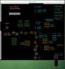
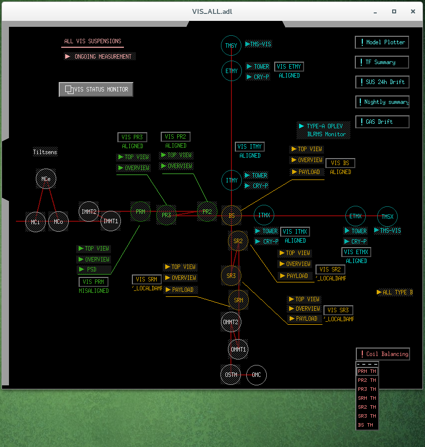
3. Now you have a button in VIS_ALL.adl and you can run the script from there with nominal configurations for each suspension (see attached).
Next:
- Modify the script to make it work for Type-C.
- Run the script for PRs and BS.
I updated the balanceCOILOUTF.py script to support Type-C suspensions with oplev (does not work for OMMTs and OSTM).
Now you can balance the coils of MC and IMMT suspensions by, for example,
python /users/Commissioning/scripts/diagonalization/balanceCOILOUTF.py IMMT1