Reports 1-1 of 1 Clear search Modify search
VIS (EY)
lucia.trozzo - 0:05 Thursday 15 August 2019 (9981) Print this report
ETMY ID: geophones and LVDT (L and T) blended at 130 mHz

In the First version of ID implemented at ETMY, using geophones, I set the blending frequency for L and T at 180 mHz: in this configuration the loops were stable, but seismic noise was not suppressed.
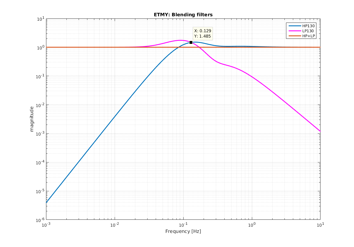
So I tried to implement a new version of ID moving the blending frequency from 180 mHz (in L and T) to 130 mHz.
Before I worked a bit on the optimization of the geophone signal:
1) I added a DC cutoff at 3 mHz
2) An integrator convert the output signal of each geophone into displacement
3) Taking into account that the output signal is displacement, I calibrated the geophones  and I measured again the sensing matrix (following the procedure describe in the see klog 8327)
In this way, we should avoid instabilities,  crossover oscillation in to the loops,  and re-injection of the geophone noise, when we reduce the blending frequency.
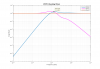
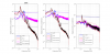
4) I implemented the the new blending frequency (LP130, HP130 Pic1).
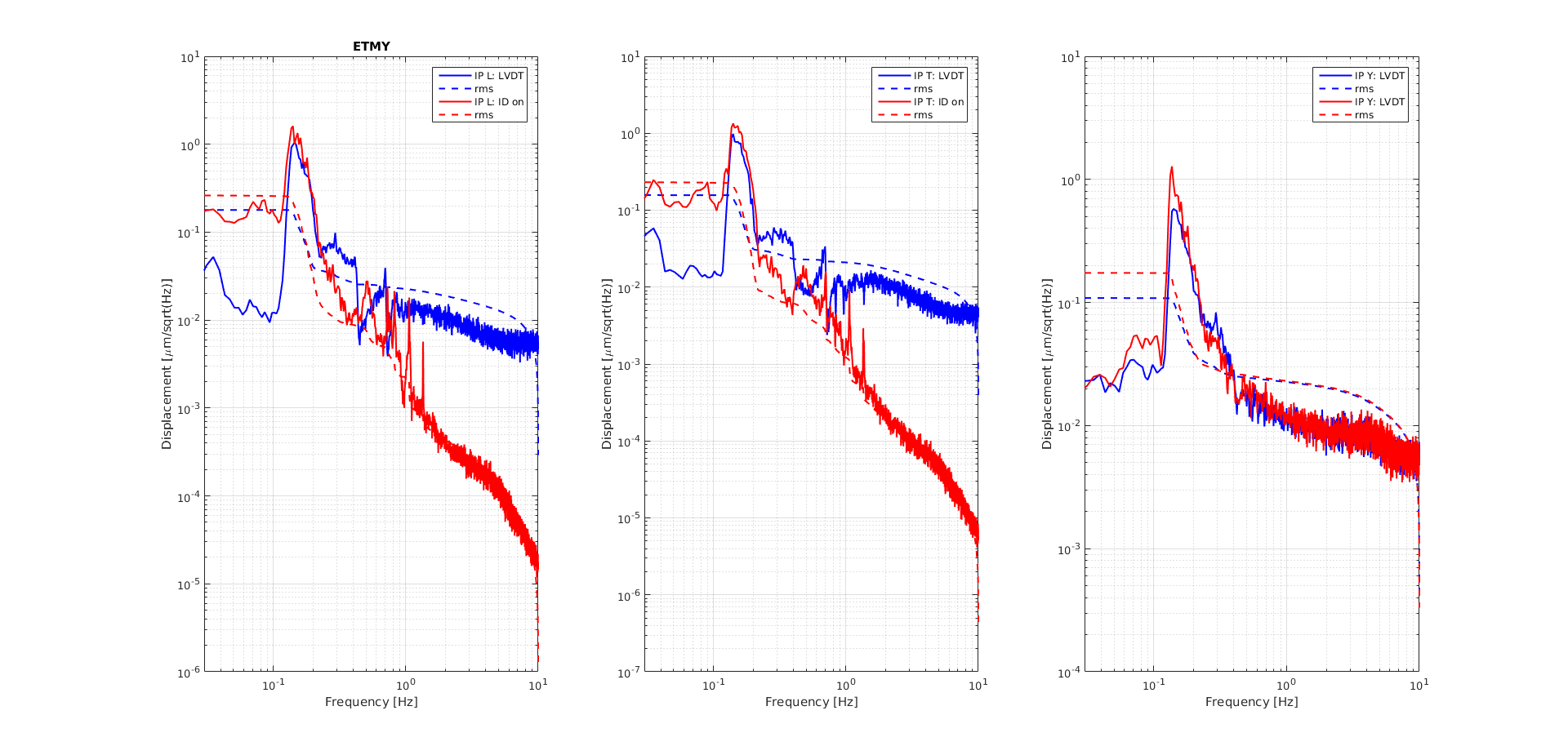
5) I turned on the ID only along L and T with UGF at 0.12 mHz.
6) Y is controlled with LVDT.
 

The loops are stable.

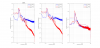
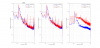
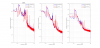
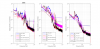
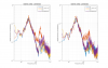
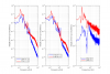
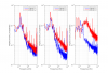
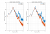
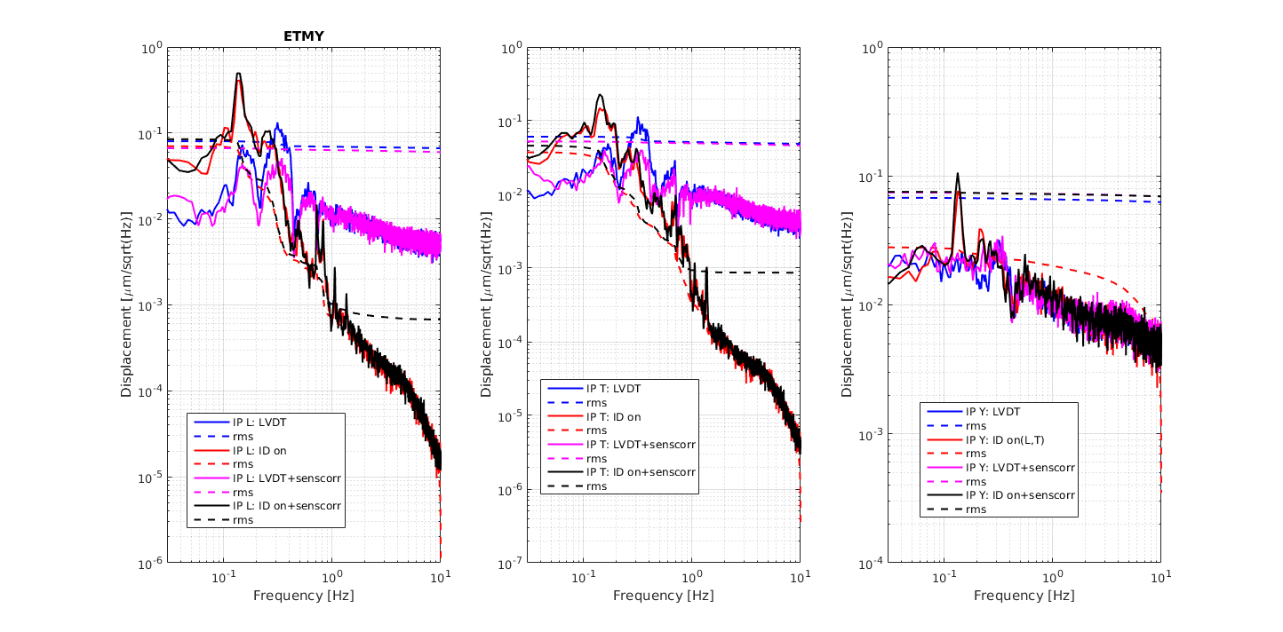
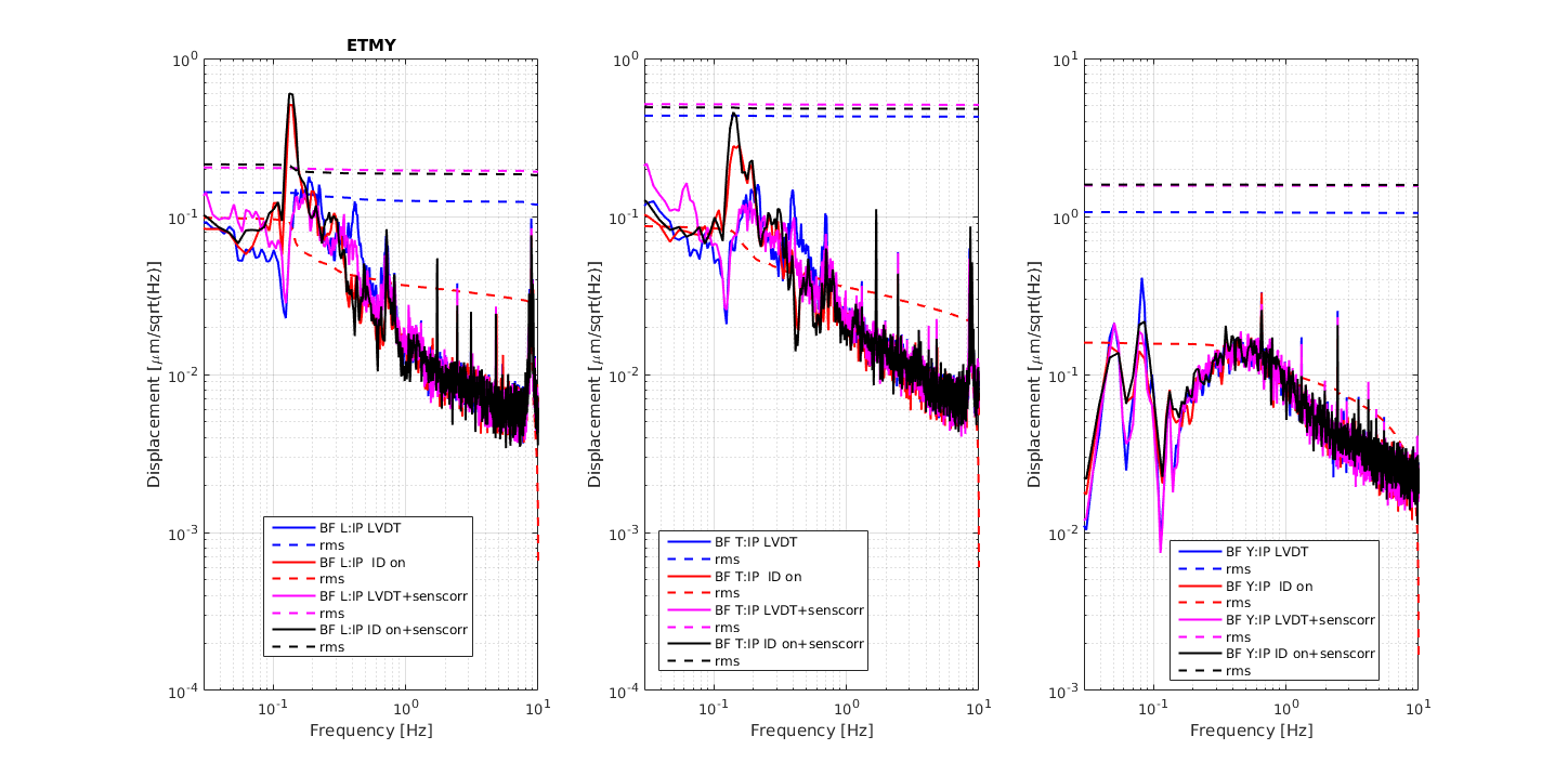
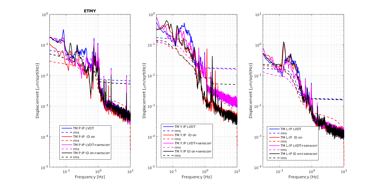
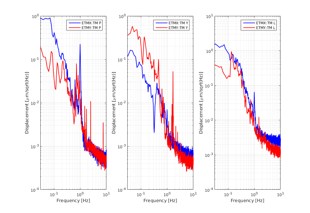
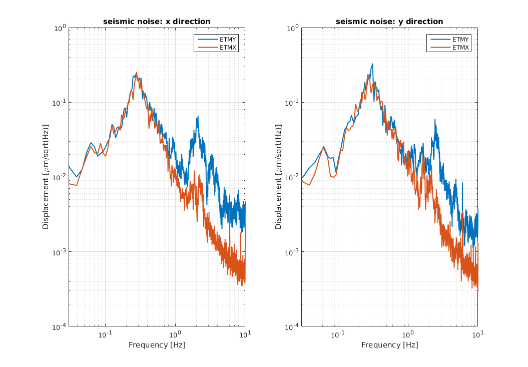
In Pic 2, Pic2 and Pic4 the SPectra of IP (with and without ID), BF (L,T,Y) and TM (P,Y,L) are shown.

We can see that

1) the residual motion and RMS of TM and BF (L and T) in both configuration are not so differents, whil BF Yaw has a strange shape: to investigate.

2) From 0.1 to 0.3 TM P, Y and L motion is reduced because of the ID, but the peack at 150 mHz is dominat.

Note: In both configuaration BF_L , BF_T damping loops and the IP sensor correction were also turned on.

%% RMS values

  IP BF
ID: rms L 0.2 micrometers 0.8 micrometers
ID rms T 0.2micrometers 0.8 micrometers
ID: rms Y 0.2 microradians 0.2 microradians
LVDT: rms L 0.15 micrometers 0.8 micrometers
LVDT: rms T 0.15micrometers 0.8 microradians
LVDT: rms Y 0.2 microradians 0.1 micrometers
TM: rms P ID: 0.1 micrometers LVDT:0.1 microradians
TM : rms Y ID: 0.1 micrometers LVDT: 0.1 microradians
TM: rms L ID: 1.1 microradians LVDT: 1.1 micrometer
Images attached to this report
Comments to this report:
lucia.trozzo - 20:51 Friday 30 August 2019 (10228) Print this report

Today I worked a bit on the optimization of the ID for ETMY

As reported in klog  9981  last time I tried to move the blending at 130 mHz to test the stability of the geophones.

The loops were stables,but something strange happens to BF.

Suspecting a large geophones noise re-injection below 0.1 Hz,  I implemented the same configuration  running at ETMX (see klog 10187)  and I checked the results.

The loops are stable.

In Pic 1 Pic2 and Pic3 the SPectra of IP , BF (L,T,Y) and TM (P,Y,L) and the relative rms, when the following configuration on the IP are implemented, are shown:

-Blu: IP in position control

-Magenta: IP Position control+ IP sensor correction

- Red : IP ID on

-Black: ID+ sensor correction on

We can see that:

1) IP RMS  in the configuration ID+ sensor correction  is 0.05 micron in L and T, but the peak at 0.130 Hz growing up.

2) In both cases (ID and ID + sens correction on) the  BF RMS  is 0.1 micron in L and T and 0.3 microradiands, but the peack at 0.130 Hz is growing up (investigation on going).

3) From 0.1 to 0.3 TM P, Y motion is reduced because of the ID, but the peak at 0.130 is dominant

I also compared the spectra of ETMY and ETMX (see Pic5, Pic6, Pic7) in the same configurations.

Looking at the spectra:

-residual motion of IP EX is lower than EY in L, T and Y

-residual motion of BF in L, T in both suspensions are comparable except for the peak at 130 mHz.

- the BF Y in EX is less noisy than BF Y in EY.

- the TM P & Y in EY are less noisy than  in TM P & Y in EX, while residual motion of TM L in both suspensions are comparable.

I don't know the reason of this strange behavior in ETMY: one possibility could be thath the geophone at EY are more noisy than those at EX and for this each blending below  200 mHz could trigger the strange behavior at EY.

Next to do: 

-move the blending above 200 mHz and check the behavior of lower part.

-measure the BF OL TFs when the ID is on and check if some phase instability in the BF  loops can explain the growing up of the 0.130 Hz.

- optimize the gain of the IP sensor correction loops by using the procedure reported in klog (10164)  and as well for the BF.

Work i n progress..

Images attached to this comment
Search Help
×

Warning

×