Reports 1-1 of 1 Clear search Modify search
VIS (EX)
yoshinori.fujii - 0:37 Wednesday 28 August 2019 (10164) Print this report
A quick test for sensor-correction-gain tuning

Lucia, Yoshinori,

= ETMX =

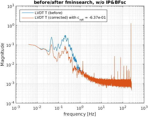
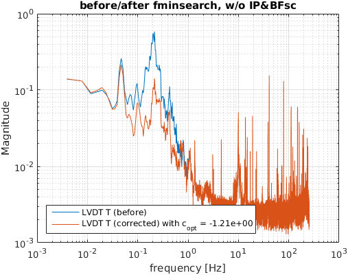
  • We look for a better gain for the LVDT sensor correction, by finding a mimum of a function.
  • So far, the sensor-correction-gains were set to 1 from just a simple guess.
  • Then, we find the gains as following:
  • dof gain
    IP-L -0.715
    IP-T -0.637
    BF-L -1.51
    BF-T -1.21

== what we did ==

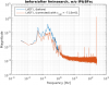
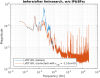
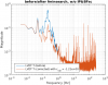
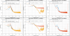
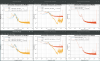
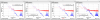
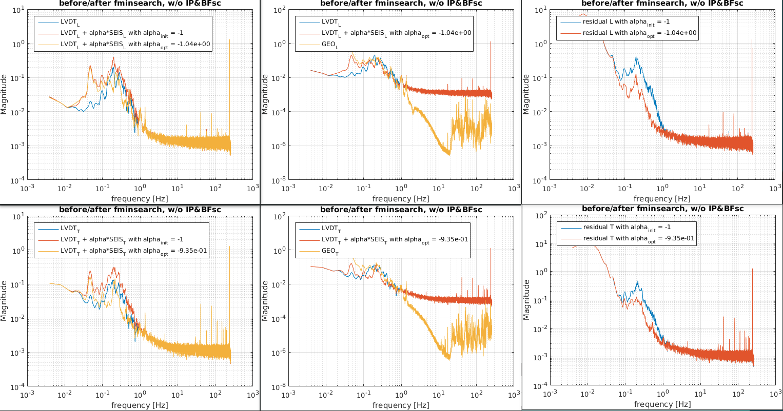
  • we looked for a mimum of the following function with a parameter, alpha:
    • func = SUM( abs( FFT[ ( X_LVDT + alpha * X_SEIS ) ] )**2 ),
    • where X_LVDT and X_SEIS are the time series data when the sensor correstion paths are opened. (w/ IP-dcdamp and BF-damp).
    • In this investigation, a frequency band from 0.1 to 0.5 Hz was selected based on the coherence between the ground motion and the LVDT sensors.
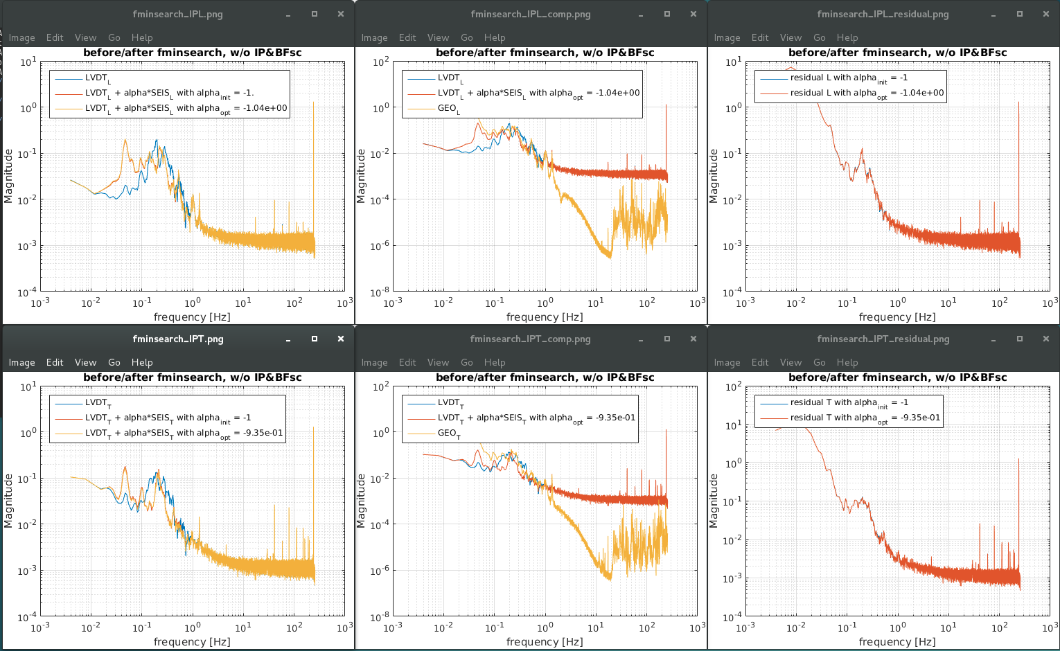
    • The corrected-LVDT spectra are attached with the estimated gain alpha (figure1 to 4).
    • They are not implemented to the MEDM screen yet. Some test is necessary before doing that.
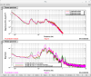
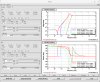
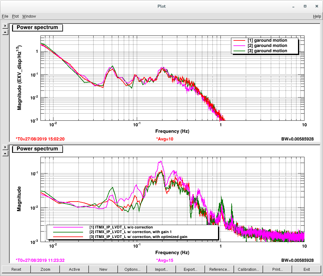
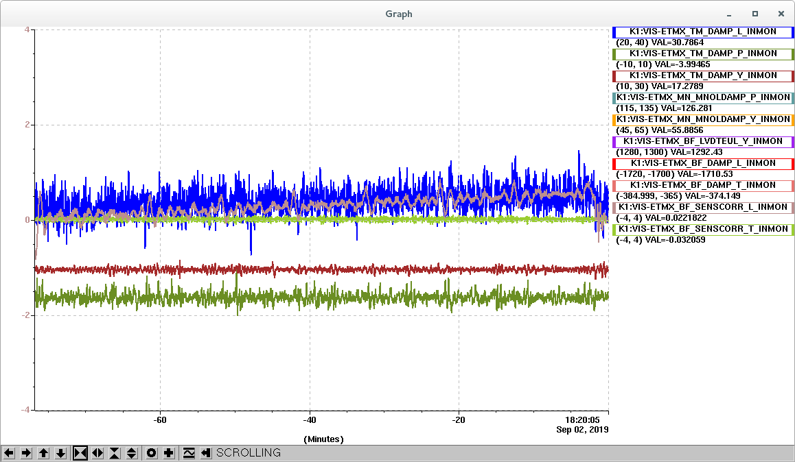
      • It does not look there is difference between the config with gain -1 and with the optimized one, indeed (figure 5).
      • The performane/improvement with the obtained gains will be checked more in detail for the next.
Images attached to this report
Comments to this report:
yoshinori.fujii - 0:49 Thursday 29 August 2019 (10179) Print this report

Koseki, Yoshinori,

  • We found that the cost function I used was (X_LVDT + alpha*X_SEIS) not appropriate, and it seemed that it would be better to minimuize the following function:
    • func = ( X_LVDT + alpha*X_SEIS - X_GEO )
  • With the test, we obtained the following sensor correciton gain:
  • dof correctiob gain apha
    IPL -1.04
    IPT -0.935
  • The attachement format is:
    • LVDT: displacement signal between ground and IP
    • SEIS: seismometer signal on the ground in dispacement
    • GEO: veocity sensor signal of IP, converted to displacement
    • residual = [ (LVDT + alpha*SEIS) - GEO ]
  • performance confirmation will be done.
  • Other reported follows.
  • ref: /users/VIS/TypeA/ETMX/feedforwrding/gain_adjustment/test/
Images attached to this comment
yoshinori.fujii - 21:45 Monday 02 September 2019 (10268) Print this report

K. Miyo, Y. Fujii,

Brief update:

  • Concerning the plot in klog#10179, it was found that the sign of the initial value was opposite from the optimal one. Figure 1 is the revised one; gain optimization did not change the situation. Basicaly the gain was aready aligned.
  • Except for this, for further tuning, we tried to modify the sensor correction filter for IP-L, so that the phase shift at around 0.1 Hz is 0 deg.
    • Figure 2 shows the tested filters:
      • brown: the currently implemented one, 6th-Butter w/ 30mHz cut-off (1)
      • green: 6th-Butter w/ 10mHz cut-off (2)
      • red: 2nd-order, 80dB-attenuation, 10dB-passband, 0.01Hz cut-off (3)
    • Figure 3 shows the comparison between the corrected-VDT and the geophones:
      • w/o sensor-correction(sc) | (1) | (2) | (3)
      • It seemed that the TML oplev signal just showed the ground motion or noise level, and no obvious improvement was observed. To be checked (with simuation as well).
      • It was found that the (3) fiter made a long-term drift as shown in figure 4, the low frequency shape of thte filter would be modified. The brown is thte output of the correction filter, and the blue one is the TML oplev signal.
  • Now the configuration is back to the this  morning's.
  • For next:
    • modify the sc-filter in lower frequemcy region.
    • check the performance with the silumation.
    • modify the IP loop hsape/gain.
Images attached to this comment
Search Help
×

Warning

×