Reports 1-1 of 1 Clear search Modify search
PEM (Center)
Carl Blair - 17:13 Monday 16 February 2026 (36369) Print this report
Jitter Coupling Investigations

[Kenta, Alex, Washimi, Yokozawan, Carl]

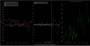
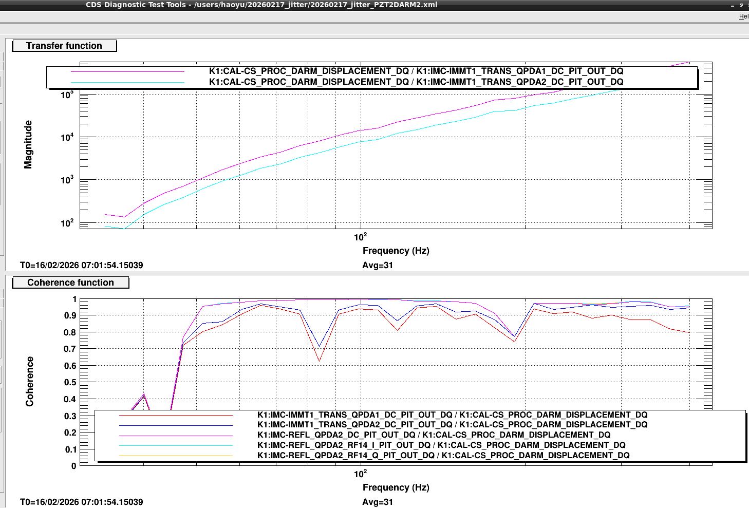
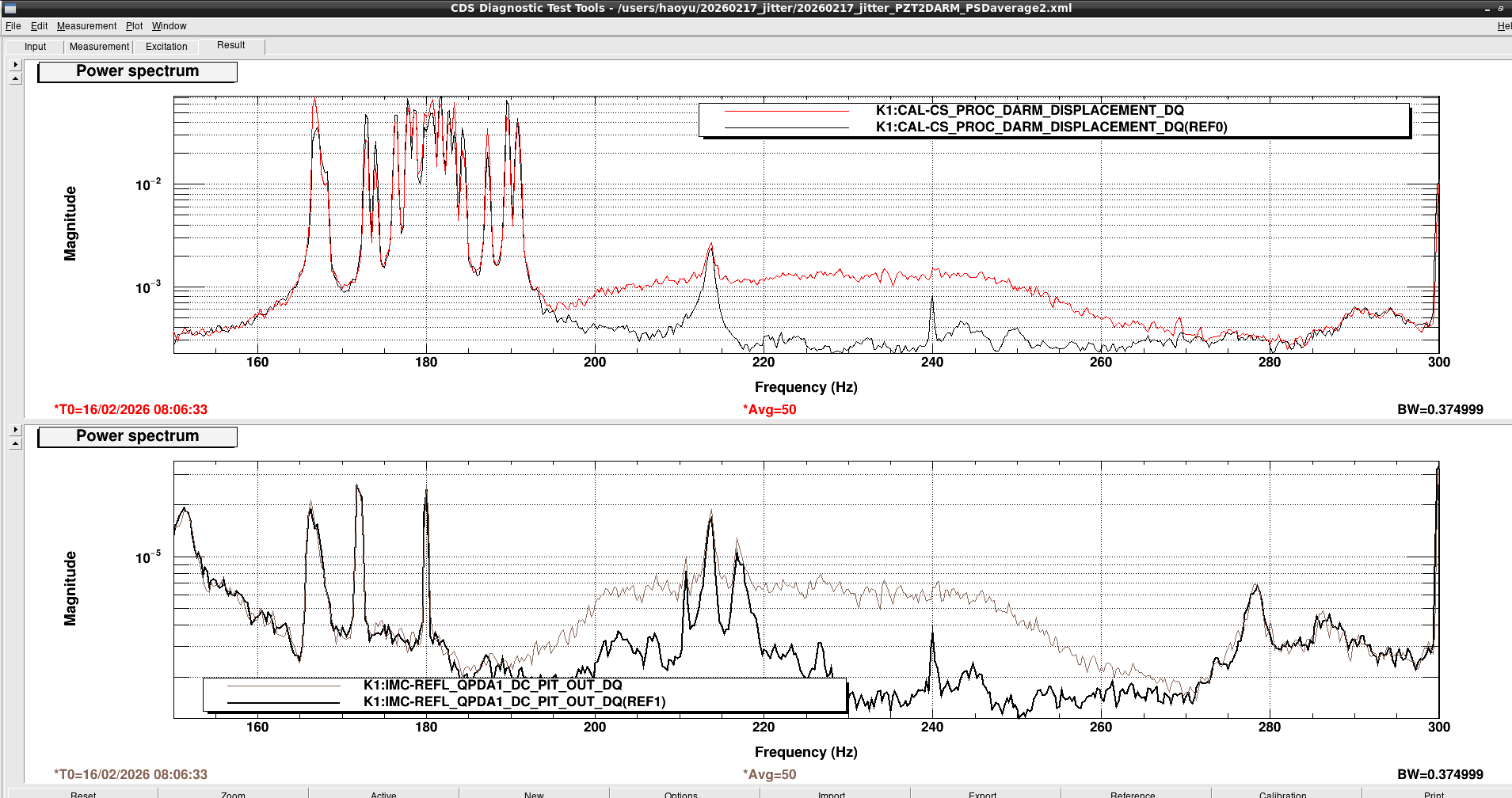
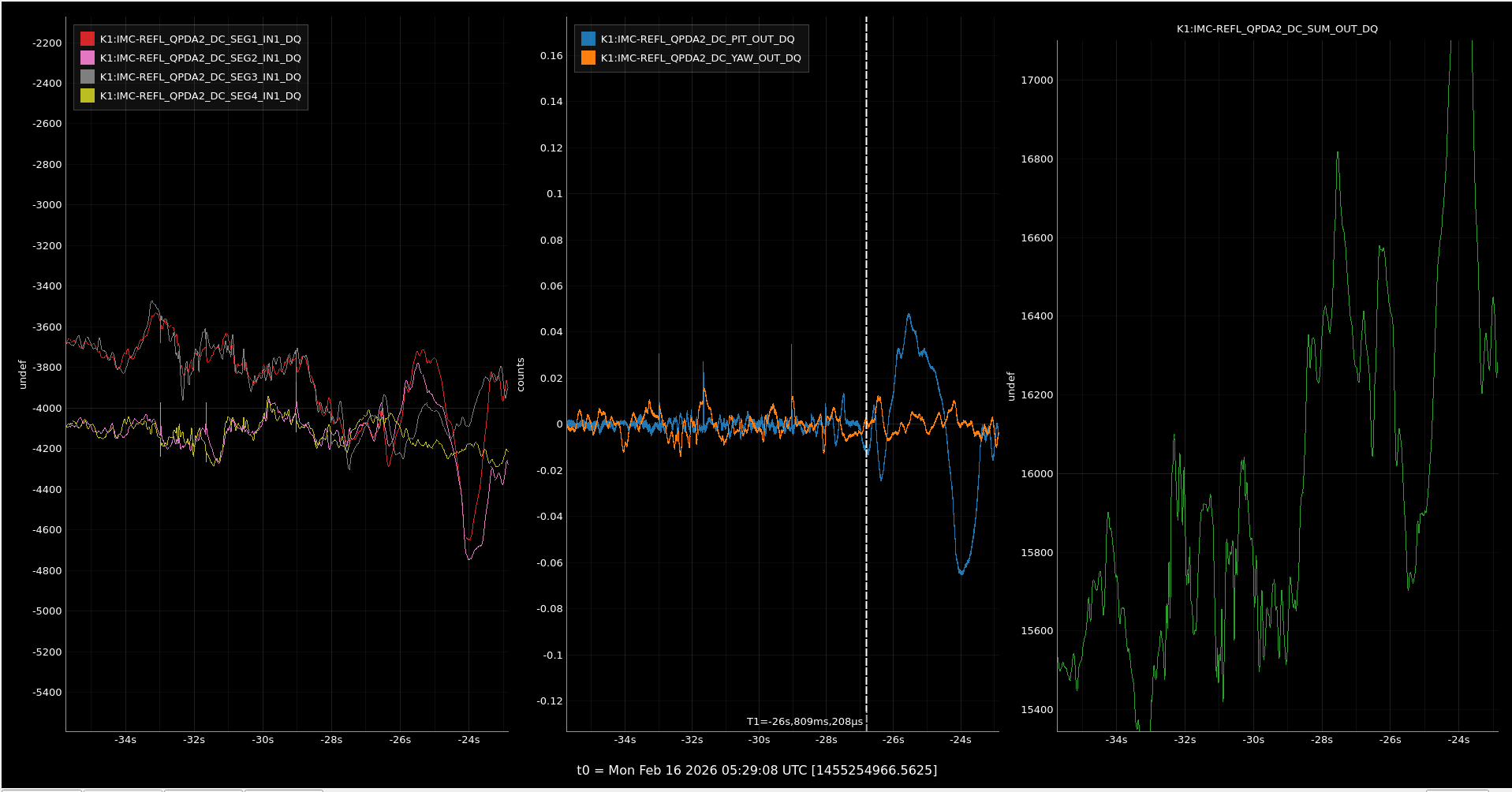
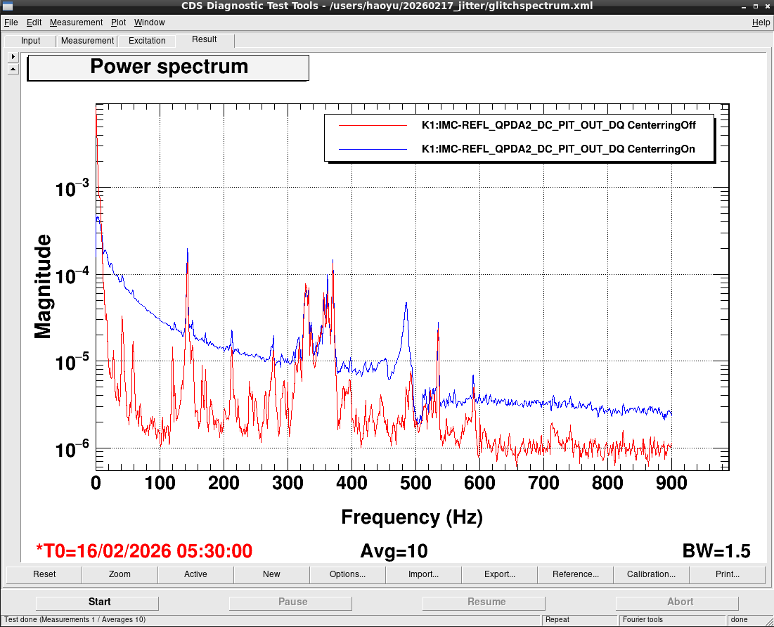
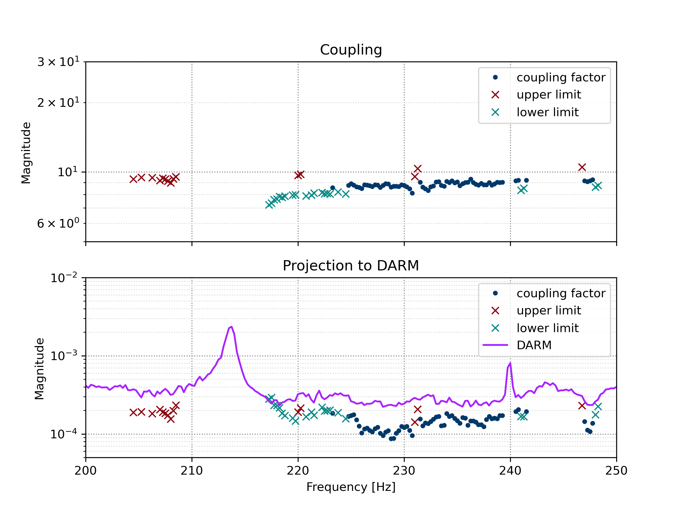
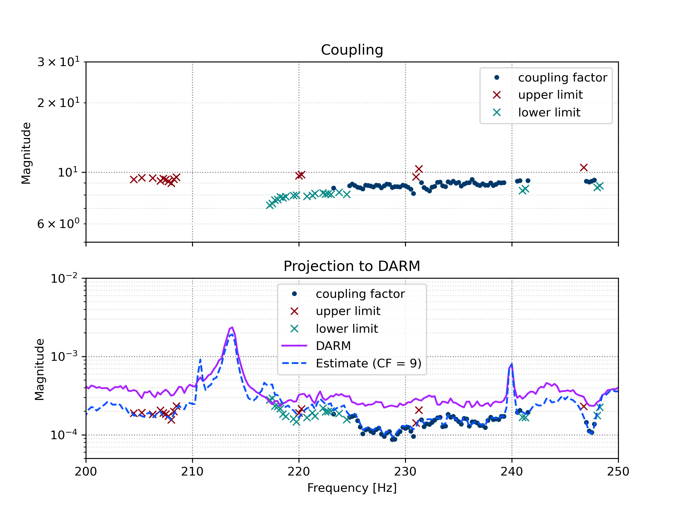
We would like to improve jitter coupling projections.  Previously the mode cleaner was used to excite jitter 40-200Hz and IMMT2 trans QPDs were used as witness sensors to project that jitter noise to DARM.  The mode cleaner was only excied in one degree of freedom, exciting MCE.  We had tried but failed to excite the other degree of freedom (with MCI and MCO).  The shaker tests might indicate jitter noise can be excited on the PSL table.  We therefore planned today to excite angle at mirror M17 on the PSL table with a linear combination of IMC PZT1 and PZT2 to see if we find the same coupling function as the shaker test noise projection around 210Hz.  We found that PZT1 was saturated and that QPDA1 was very noisey so wee did not make the measurement exactly as planned.  The PZT needs manual ofloading, we will do that tomorrow.  QPDA1 glitches seem to comer fom the piezo in the centerring loop on the QPD.  When the loop is opened the glitches stop (but the low frequency beam position noise increases).  We made a measurement in PZT2 pitch that can be used for noise projection.  One a swept sin measurement and another a broadband measurement focussingon the 210Hz coupling frequency (attached). Projectionswill be processed tomorrow.


Images attached to this report
Comments to this report:
Carl Blair - 14:25 Tuesday 17 February 2026 (36371) Print this report

[Alex , Carl] Adding some figure of the IMC QPDA2 (note typo in original klog) centerring loop glitches, first figure left shows 4 segments, middle shows pitch and yaw, right shows sum channels. Second figure shows same the moment the centerring loop is turned off. Third figure shows the centerring loop error signal spectrum, centering on and off.  

We tried to investigate further this morning.  With the IMC locked we did not see any centerring loop glitches.  Figure 4 shows QPDA2 pitch spectrum with centerring on and off (no change). We tried to make glitches by driving the piezo start 3:25:00 UTC with a 0.1Hz sin wave with amplitude up to 10V, which is more than the actuation range used during a normal lock.  We also adjusted the DC offset to match the lock from yesterday afternoon and still saw no glitches,  At 10V drive we only just start to see a coherent signal on the QPD.  This test was made after the IMC input alignment piezo was offloaded, but I can not see why they would be related.

Images attached to this comment
Alexandra Adam - 11:31 Wednesday 18 February 2026 (36384) Print this report

[Alex, Carl]

We analysed the data from the white noise injection. White noise was injected into PZT2 with bandpass filter from 200 Hz to 250 Hz and a gain of 0.6. We found that IMC-REFL_QPDA2_PIT_OUT_DQ had the highest coherence. Using the method described in Environmental Noise in Advanced LIGO Detectors we calculated the coupling function for the IMC-REFL to DARM. Where possible the coupling function is given however when the injected noise was not large enough in DARM or in the IMC-REFL the coupling is labelled with a upper or lower limit. Where neither was high enough no coupling factor was displayed. The thresholds used were a factor of 2 for the ratio the DARM ASD of the background to the injection and a factor of 2.5 for the witness sensor.

The coupling from 200-250 Hz appears to be flat with a coupling function of ~9. A comparison with this estimate is attached


Images attached to this comment
Non-image files attached to this comment
Search Help
×

Warning

×