I started redesign of ETMX hierarchical actuators to reduce the TM actuator RMS.
At this moment, IM started to oscilate at 2.1Hz if the crossover frequency between IM and MN was changed.
On the other hand, we could keep ALS_DARM even if we changed the crossover frequency between IM and TM around 6Hz.
I'm not so sure this modification is enough for reducing the TM feedback signals by a factor of 4 but I will try to use it after recovery of PRFPMI RF lock.
Abstract:
I tried to reduce the RMS of TM actuator by changing the crossover frequency between IM/MN and TM to higher frequency.
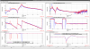
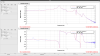
I succeeded to increase the corssover frequency at 6Hz (fig1: red) and 2.4Hz peak was reduced but low frequency RMS, especially around microseimic, was increased (fig2).
So, further tuning is necessary but it would take some time.
Detail will be posted tomorrow.
This is the detail of the Thursday work.
Sorry for my late post.
Detail:
I tried to increase the crossover frequency by following procedure.
1. Turn on phase compensation filter for MN to keep the relative phase between IM and MN during the following crossover frequency change work.
2. Turn off notch filters below 10Hz to reduce the phase delay around 6Hz.
3. Change the roll-off filter (eliptic low-pass filter) frequency from 20Hz to 50Hz to save the phase delay around 6Hz further.
4. Reduce the gain of TM_LOCK_L_GAIN and compensate it at DARM1_GAIN.
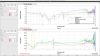
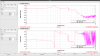
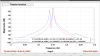
Figure 1 shows the TF from TM_LOCK_L_IN2 to TM_LOCK_L_IN1 with excitation from TM_LOCK_L_EXC, which represents the transfer function of A_TM/(A_IM+A_MN), so the high gain means the TM actuator is dominant at that frequency.
Target crossover frequency is about 6Hz, so it is necessary to reduce the gain from 1 to 0.333 but DARM started to oscilate when the gain was 0.5.
According to the TF measurement results, TM actuator gain becomes high around 2.2 Hz, which might introduce instability of the loop.
So, I added the lag filter at TM_LOCK_L to compensate the phase difference between TM and the other actuators around 2Hz, and then TM gain can be reduced to 0.333 Hz, which results the crossover frequency of 6Hz as shown in fig1.
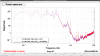
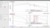
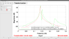
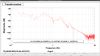
Figure 2 hows the spectrum comparison of the TM feedback signals with the nominal crossover frequency and 6Hz crossover freuency.
Thanks to the phase compensation, peaking around 2.2 Hz was reduced.
On the other hands, low frequency signals were increased due to the lag filter implemented at TM_LOCK.
Since 2.2 Hz peak reduction is still not enough (we should reduce it by a factor of 4 but now factor of 2.5) and low frequency RMS would be problematic when the microseismic becomes large, further tuning is necessary.
Since the crossover around 2.2 Hz is very complicated, it is hard to optimize by just modification of the current filter, it would be better to redesign hierarchical actuators from scratch.


Abstract:
I designed the new hierarchical actuators from scratch.
MN and IM crossover frequency is 0.4Hz and IM and TM crossover frequency is 4Hz in the new design.
I will test it when the IFO can be used next week.
Detail:
As reported in the previous post, it seems very hard to optimize the hierarchical actuator by modifying current filters, so I designed the filter from scratch.
First I measured the ETMX TF by exciting each stage from CAL excitation port to keep the actuator balance as LSC actuators.
During the measurement, I turned off MNH, IMH, BFH dewhitening filters to avoid saturation.
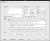
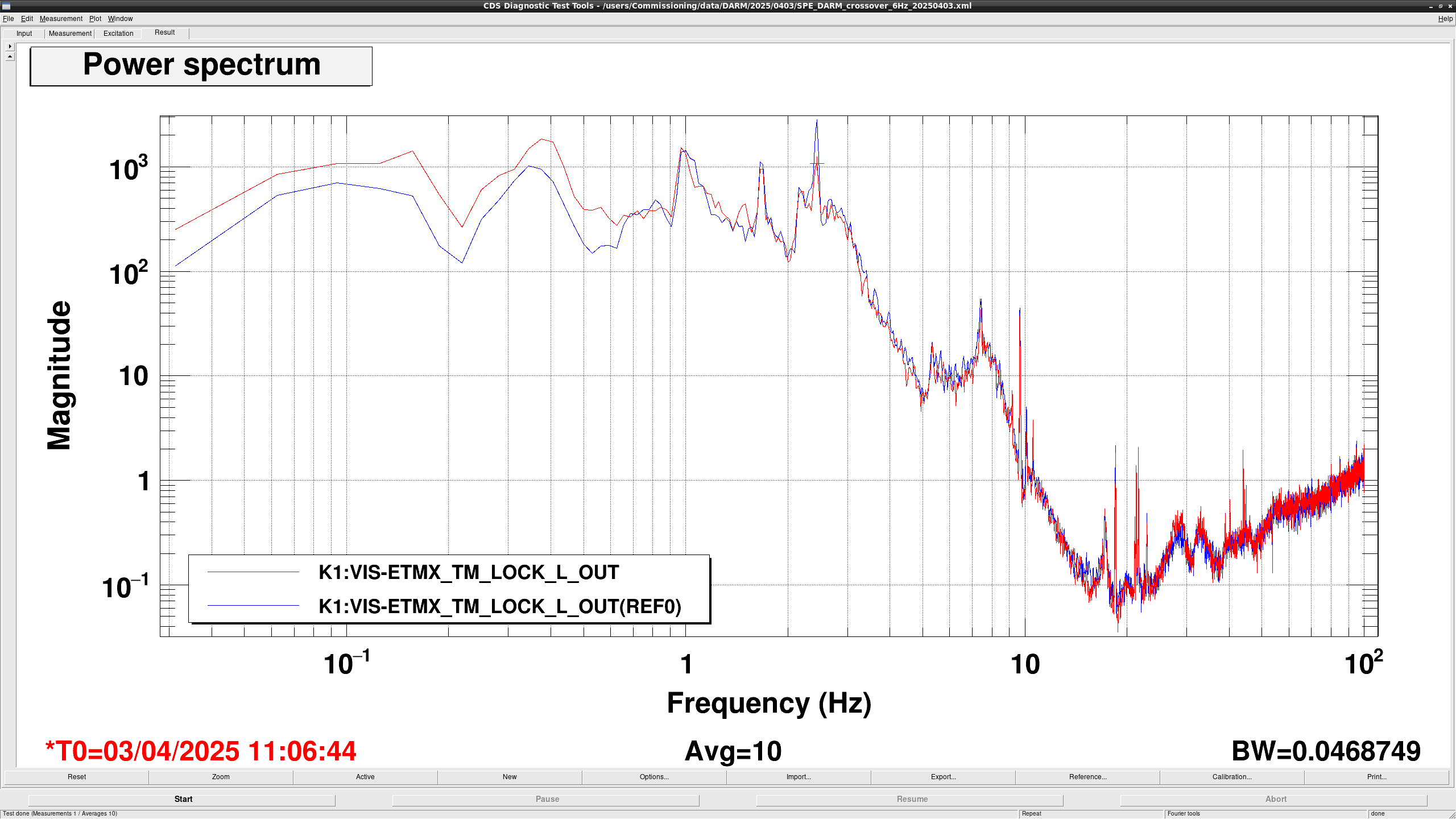
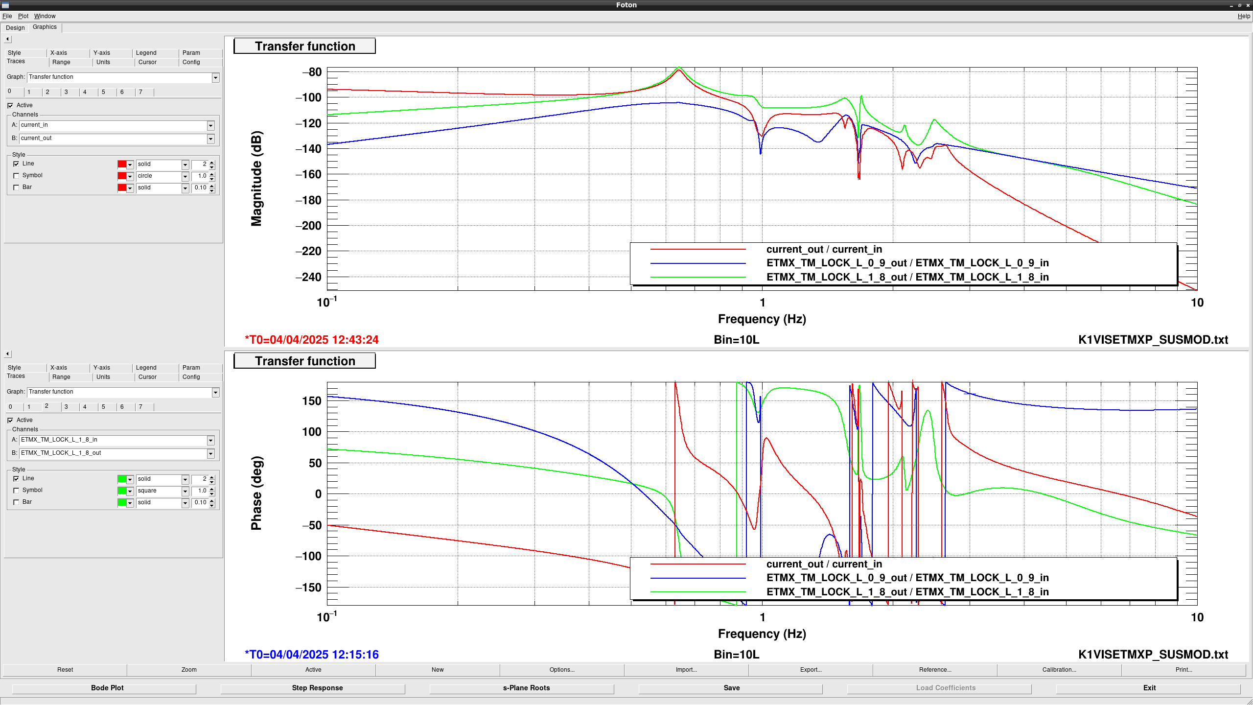
After the measurement, I designed the filter at foton file for SUSMOD as shown in fig1.
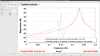
figure 2, 3, and 4 shows the overplots of measured TF and suspension models I made for TM, IM, and MN, respectively.
TM TF seems well modeled while phase of IM seems different around 2-2.5Hz.
Also, MN TF seems to have lower gain at high frequency but it should be fine because MN will be only used for low frequency.
According the the suspension model, it is hard to avoid crossing TM and IM actuators around 2.2Hz if we set the crossover frequency at 3 Hz, which is current nominal value.
So, I slightly increased the crossover frequency and set it at 4Hz in the new design.
Also, it was found that setting crossover frequency between IM and MN around 1Hz due to the complex resonant structure around 1Hz, the crossover frequency between MN and IM is at 0.4Hz in the new design.
Final design of the hierarchical actuator can be seen in fig 5.
I will try to test the new hierarchical actuators next week.

Abstract:
I tried to lock DARM with newly designed hierarchical actuators but failed.
Though the reason is not clear, DARM loop oscilated at 2.1Hz.
According to the phase behaviour around 2.1Hz, there seems to be negative zero around there.
So, decoupling of the actuator might solve the problem.
Detail:
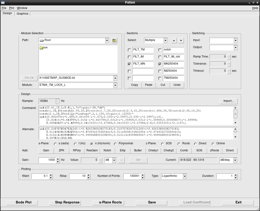
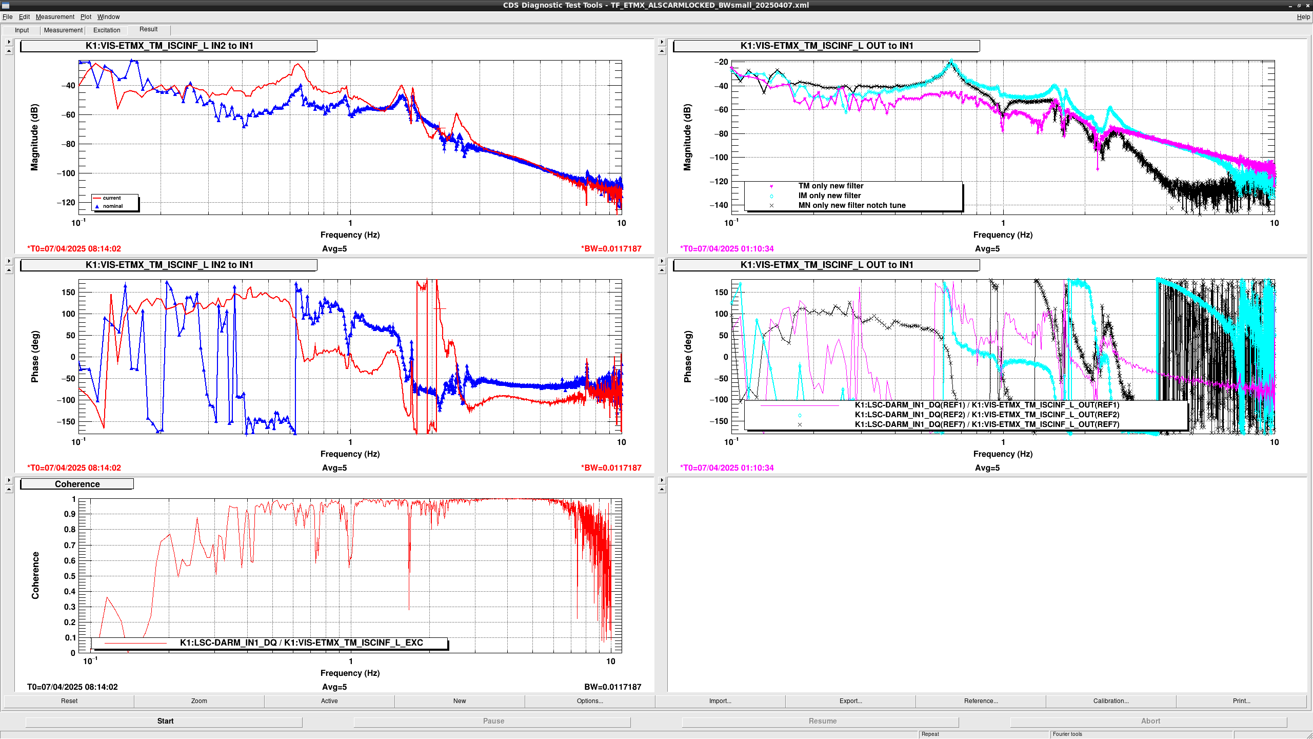
First, I measured transfer function from ISC_INF_EXC to DARM1 with only turning on one of MN, IM, and TM actuator switches with ALS_CARM_LOCKED state (fig1:right column).
Pink, cyan, and black lines show the TF when only TM, I, and MN actuators were opened, respectively.
I slightly tuned the notch filter frequency for MN filters but basically the designed filter seemed to be as expected.
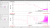
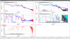
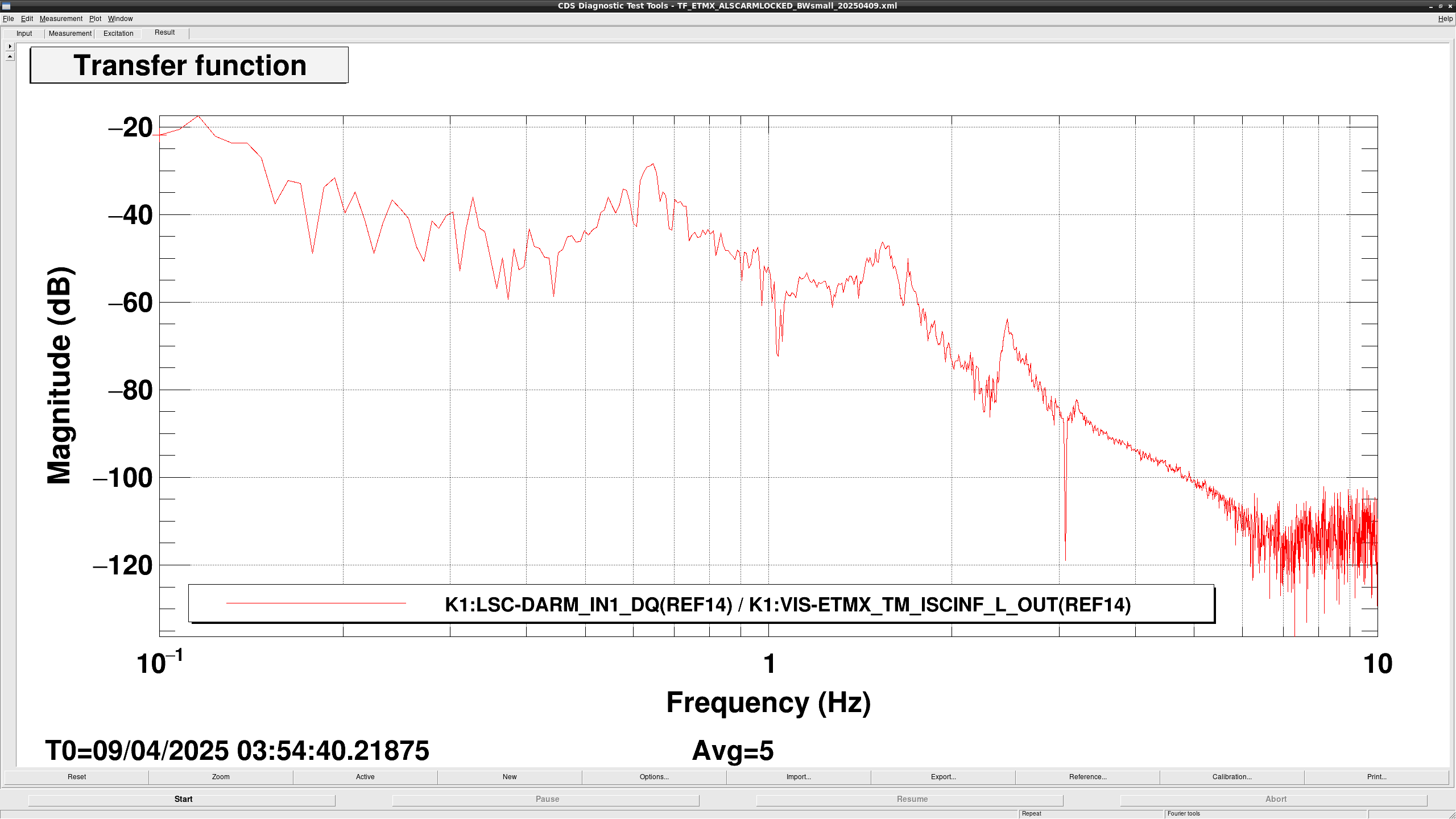
Then, TF from ISC_INF_EXC to DARM1 with turning on all actuator switches with ALS_CARM_LOCKED state (fig2: left column).
Red and blue lines show the TFs with nominal filters and newly designed filters, respectively.
With the initial design, hollow around 1.9 Hz is too deep, so I tuned the notch filter of TM _LOCK_L to mitigate it.
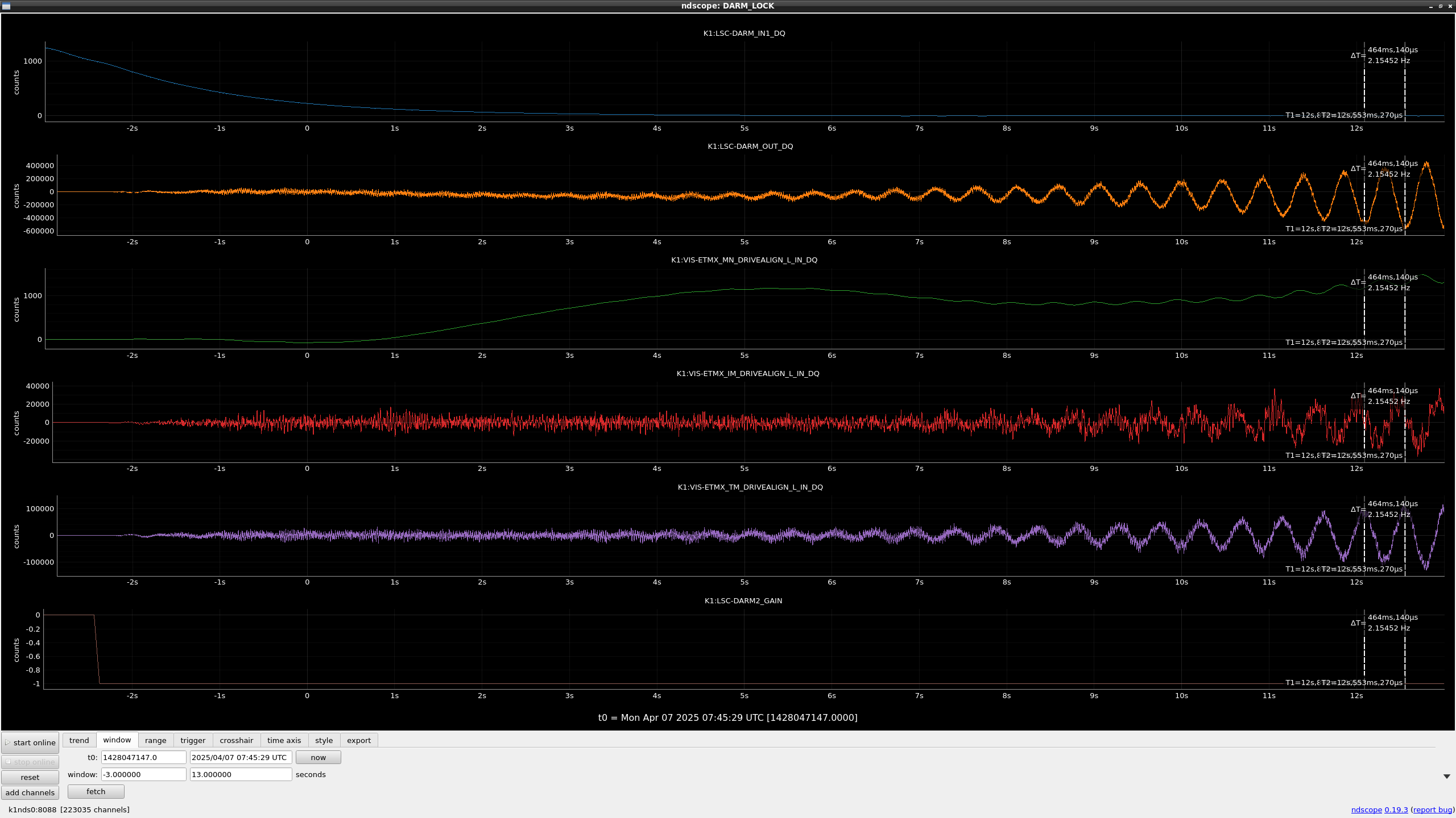
After that, I tried to lock the ALD_DARM with new hierarchical actuators but started to oscillate at 2.1Hz (fig2).
2.1Hz gain should be enough high after engaging ALS_DARM, so it doesn't seem gain peaking.
According to the TF in fig2, the phase was rotated by 360 degrees between 1.7Hz to 2.5Hz, which implies that there was a negative zero around that frequency.
If there is a negative zero around 2Hz, actuator sign at 2.15 Hz resonance would be flipped, so oscillation might be explained.
I'm not so sure why there was a negative zero but one possibility is actuator coupling from the other DoFs, so actuator decoupling should be performed.
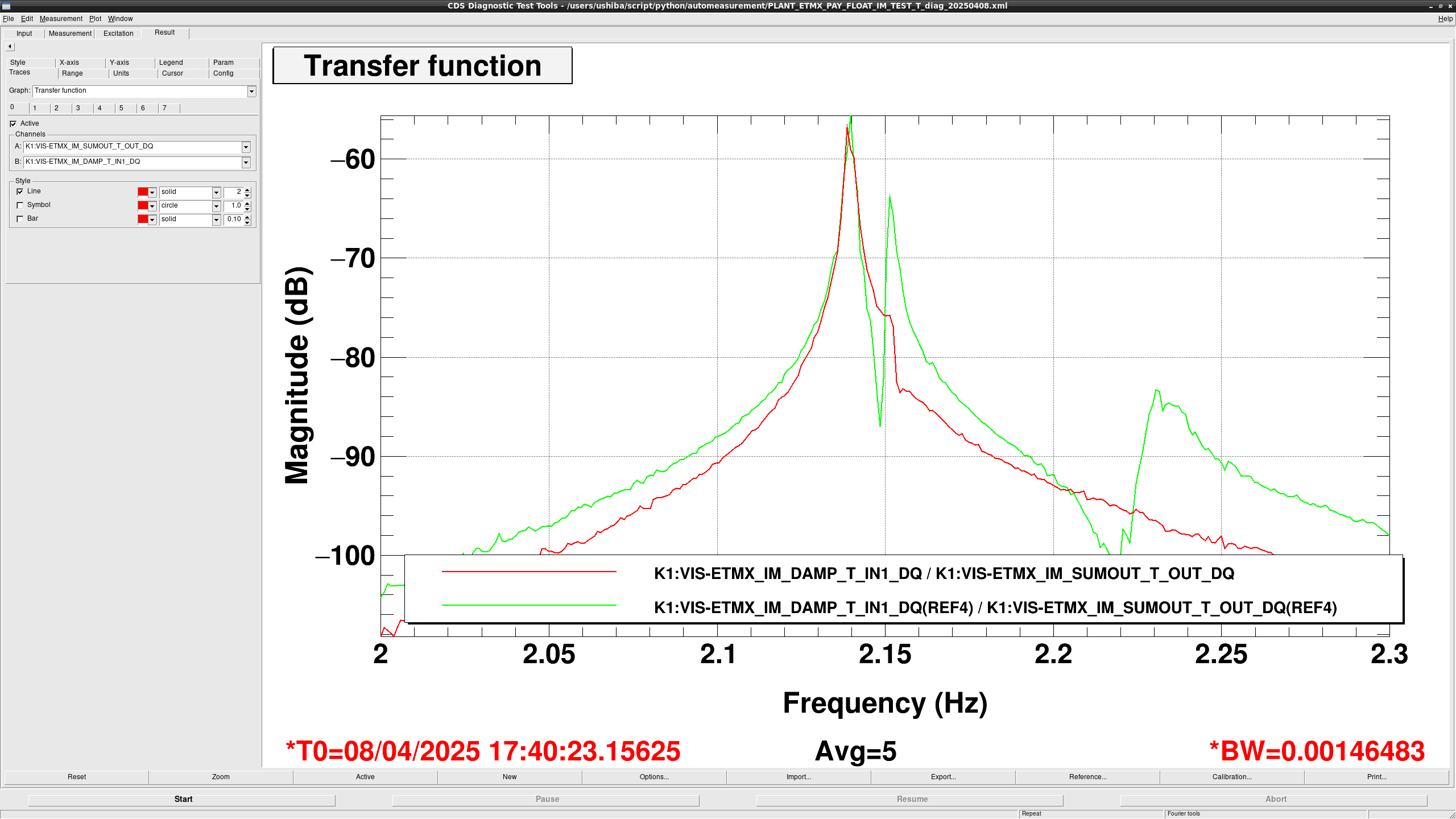
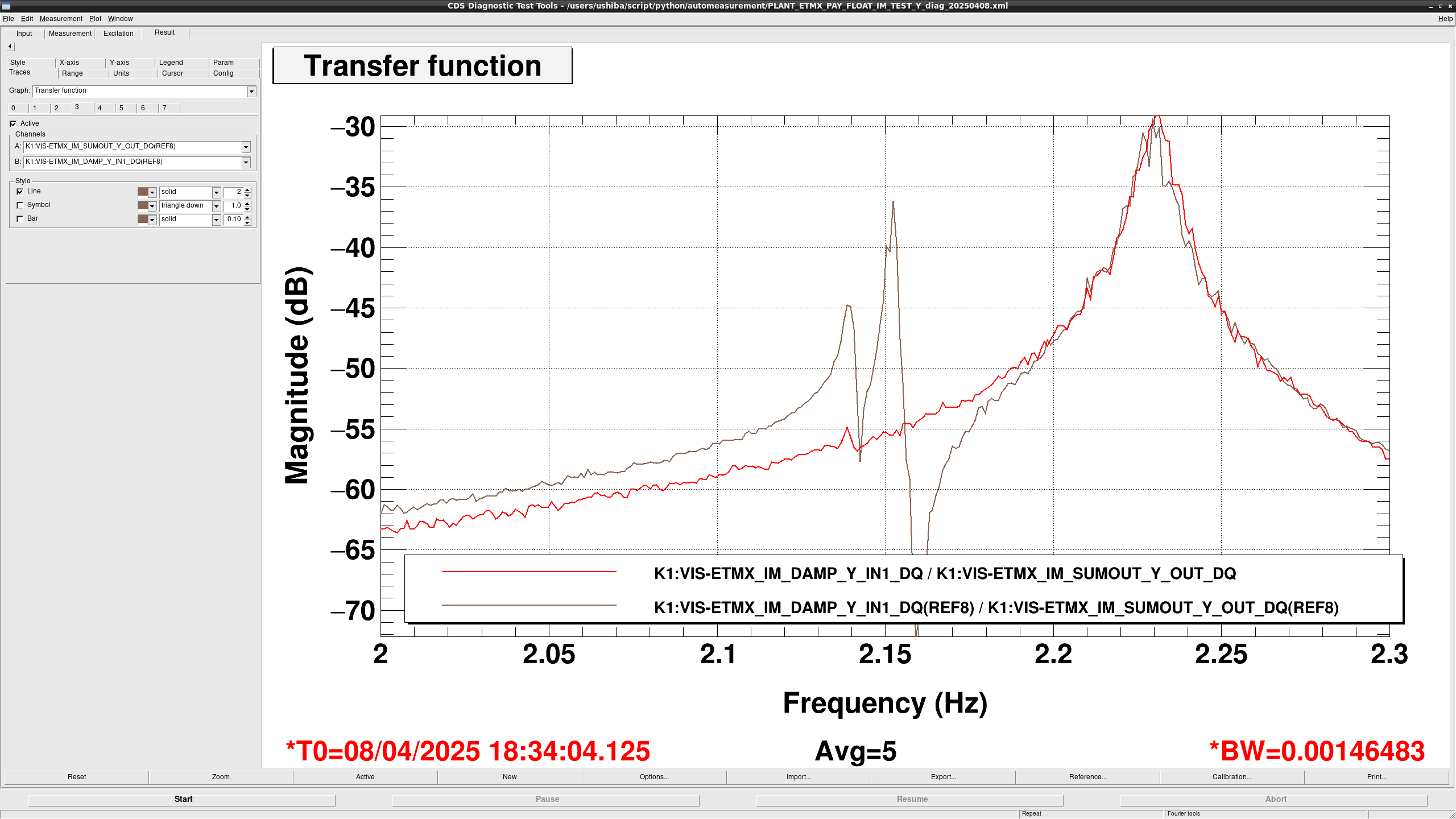
For the actuator decoupling, I first decoupled IM horizontal photosensors.
To decouple them around 2Hz, L, T, Y resonances at 2.15, 2.14, and 2.23 Hz was used.
Since the frequency difference between resonances are very small, I measured the spectrum with 1024 seconds time span with diaggui.
I calculated the sensor decoupling matrix and set them at the elements of SENSALIGN matrix of ETMX IM stage.
Also, I asked Komori-kun to run the measurement script after the night work.
If the script works well, the measurement will continue for about 3 hours and the script will request OBSERVATION_WITHOUT_LINES to LSC_LOCK guardian.
Figure 1, 2, and 3 show the TF from excitation of each DoF (L, T, and Y, respectively) to photosensors around 2Hz.
Coupling becomes much smaller, so I will decouple the actuators using these sensors.
Note:
Since I don't have enough time to check the new decoupling matrix works well, please revert them by using SDFs at SAFE state if someone notices any problems.
EY cryo payload has the same property on ~2Hz resonances? Or is it rather severe because of some photo-sensors' death?
I decoupled the ETMX IM actuators with decoupled IM phtosensors.
Though the actuator coupling around 2Hz became small, the couling at the other frequency became large.
Due to the worse actuator coupling especially around 3Hz, deep (~ 20dB) notch appeared in the TF from IM actuator to DARM (fig1), so I gave up to use the decoupled actuators.
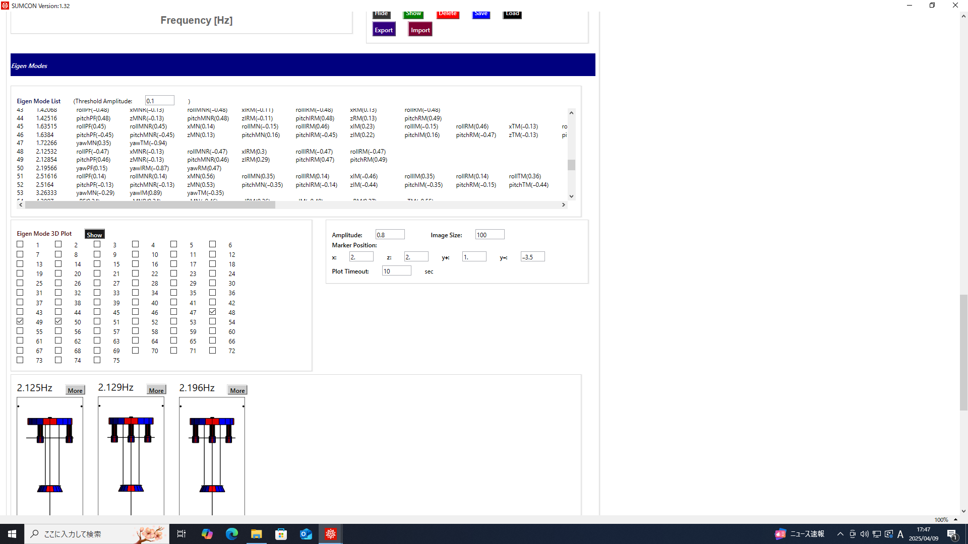
By the way, I performed modal analysis of the rigid body model of a cryogenic payload.
According to the result, mode shape of the oscillation mode around 2.1Hz has common motion at IM and MN stages: When IM/MN stage moves +x direction, IMR/MNR also moves +x direction (fig2).
Nievely thinking, if feedback signals apples the force to IM/MN tostop the suspension motion, the force to IMR/MNR applies to the opposite direction, which enhances the motion of IMR/MNR.
I'm not so sure DARM loop can be stable even with that condition?
If not, might only thing we can be just increasing the gain of damping of 2.1Hz loop not to oscillate it?

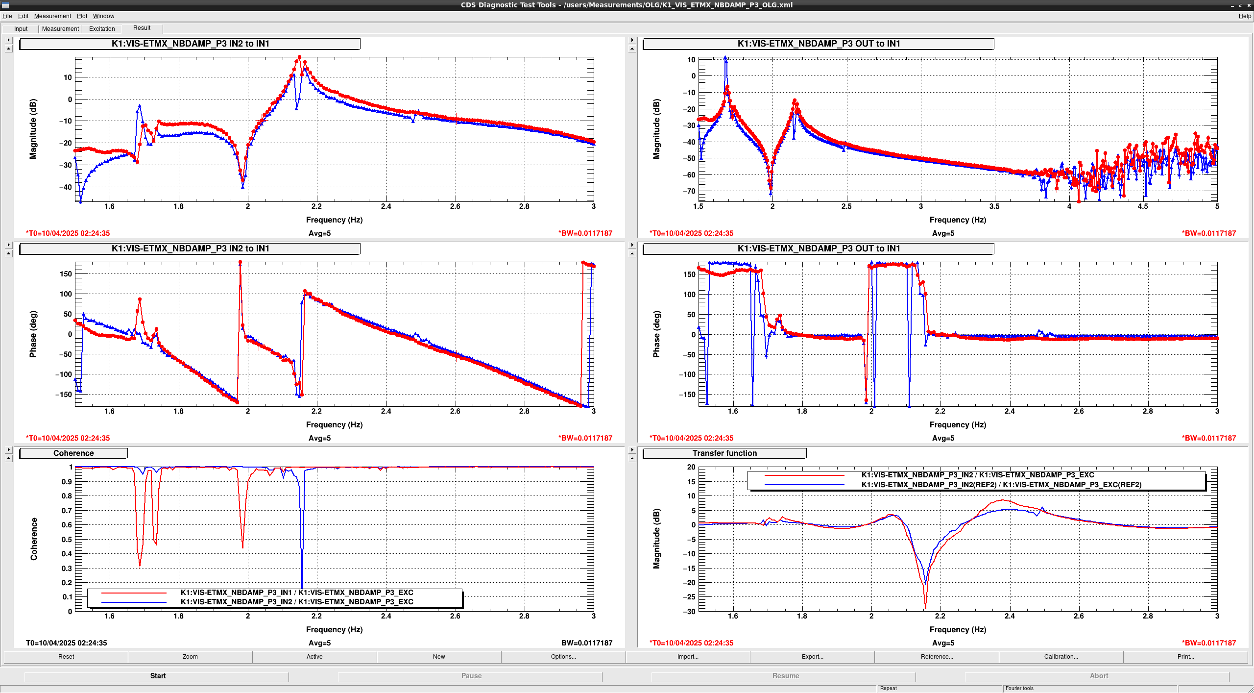
I increased the NB damping gain for 2.1 Hz resonances.
Though IM_DAMP_L signals were used for damping 2.1 Hz resonance, I changed the signals to PF_OPLEV_P signals and feedback port to MNP.
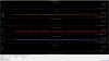
Figure 1 shows the OLTF and supression gain of NBDAMP filters I designed.
Original supression gain was 15dB or so, new damping is 5 times stronger.
After the moification of 2.1Hz resonances, I tried to close the DARM loop with new hierarchical actuators.
Thanks to the stronger damping, engagement itself was succeeded but it started to oscilate just after boost filter for DARM was engaged.
Since DARM gain is pretty high and it is almost impossible to keep the local damping gain greater than DARM gain, I gave up to close the loop with new hierarchical actuators.
So, it is necessary to consider the way to reduce the coil driver noise from using LPCD.
There are several possibility:
1. Insert the small resistances (~200 ohms or 300 ohms) between HPCD and TM actuators to reduce the actuator efficiency by a factor of 2-3.
2. Using ETMY for mass lock to reduce the TM actuator signals by a factor of 2.
3. Changing the dewhitening filter frequency to slightly higher frequency (for example 5Hz to 50Hz) to avoid enhancing 2Hz signal, which is one of the dominant signals of current TM actuator RMS.
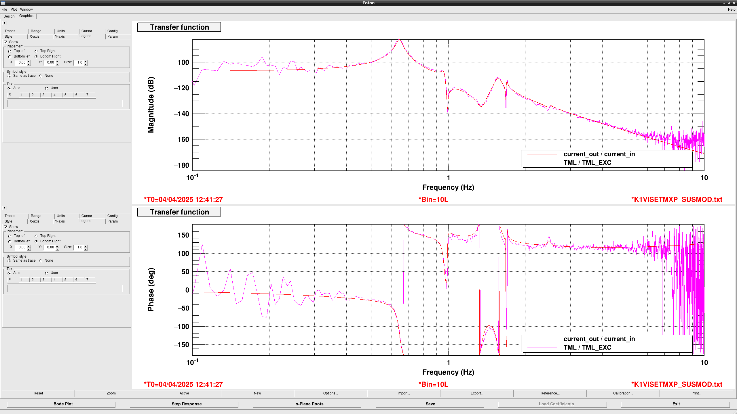
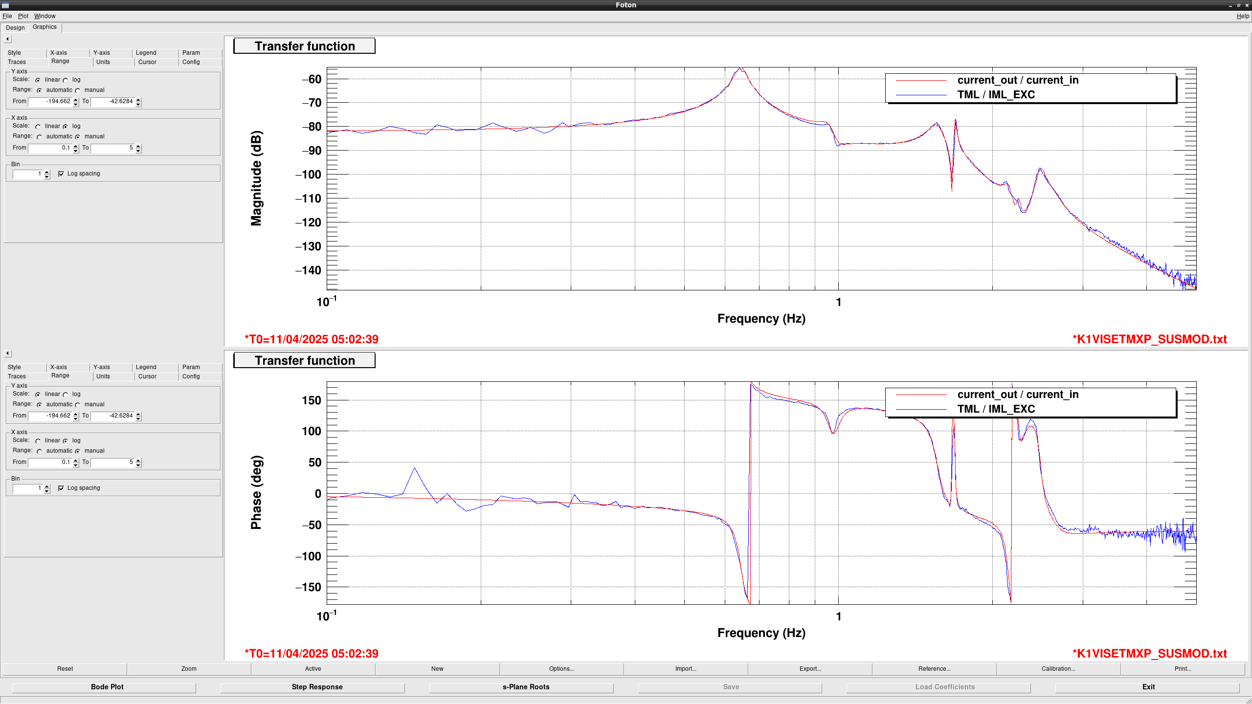
I updated the IML to TML TF model (fig1).
Difference between the model shown in klog33261 is basically zero at 2.3Hz (modified the sign of real part from positive to negative, so called negative zero).
This midification can explain the phase rotation around 2 Hz, so current suspension system somehow has a negative zero around there, which would be the problematic for the hierarchical control.