Fujii, Sato, Aso (VIS)
Ushiba, Yamada, Tomaru (CRY)
Bottom Line
- The Type-A system for ITMY is now released.
- The alignment is recovered using the OpLev as a reference.
- With this state, we observed Michelson flinges. So the alignment should be roughly OK.
TO DO
- Adjust the EQ stop distance for the cryo-payload (Ushiba, Tomaru, Yamada)
- Clean inside the chamber around the cryo-payload (Ushiba, Tomaru, Yamada)
- Health check of the suspension with TF measurements. (Lucia, Aso)
Details
Today, CRY people cleaned yet another moving mass then released the cryo-payload.
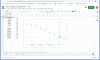
Then the VIS team tried to release the tower part, finding that some of the IP LVDT signals are freaky.
It was caused by loose connection of in-vac cables. We ended up crimping the D-Sub pins again.
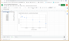
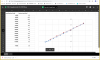
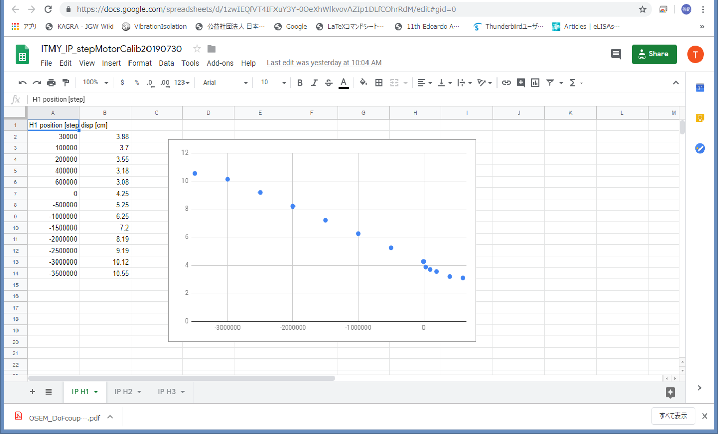
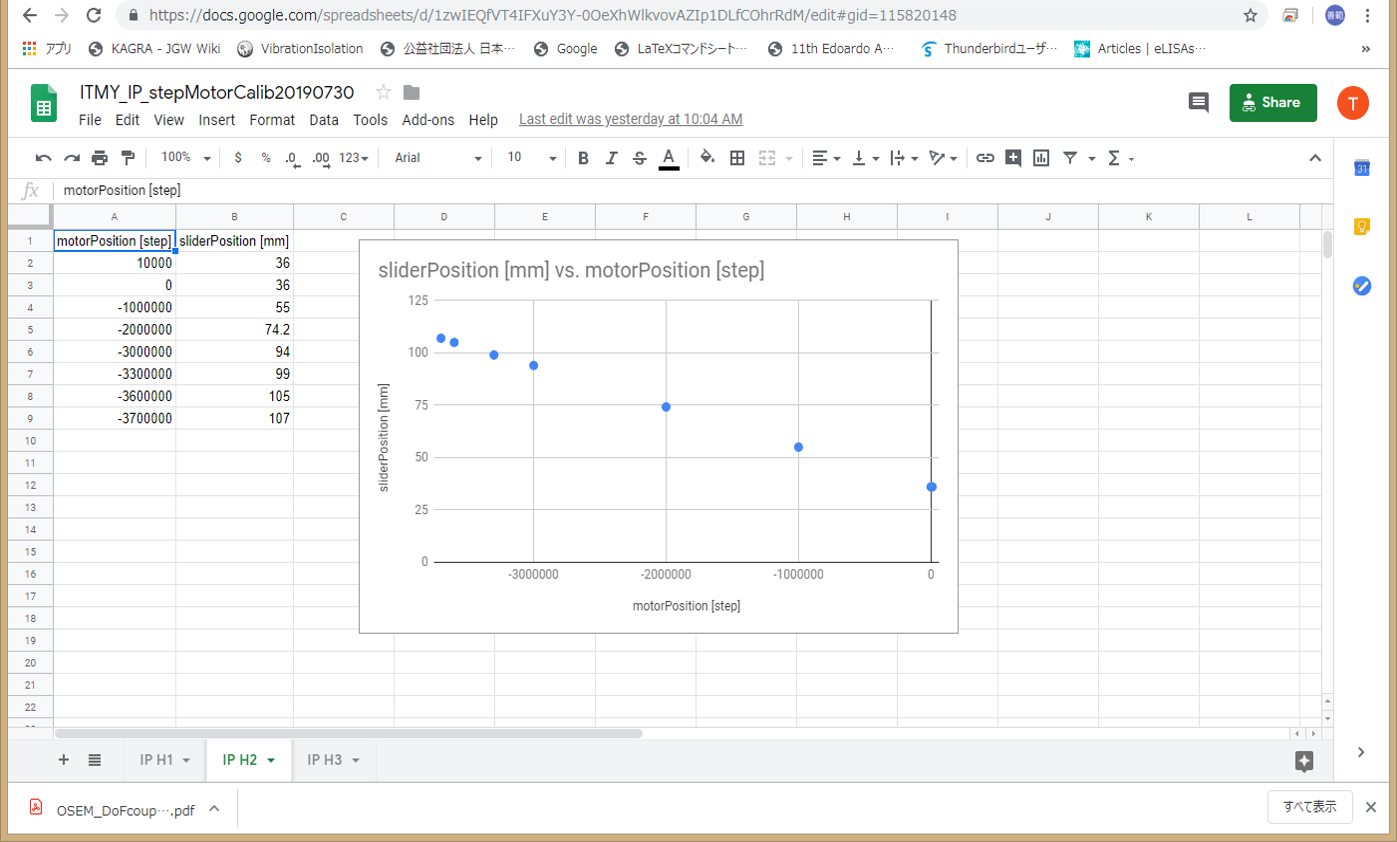
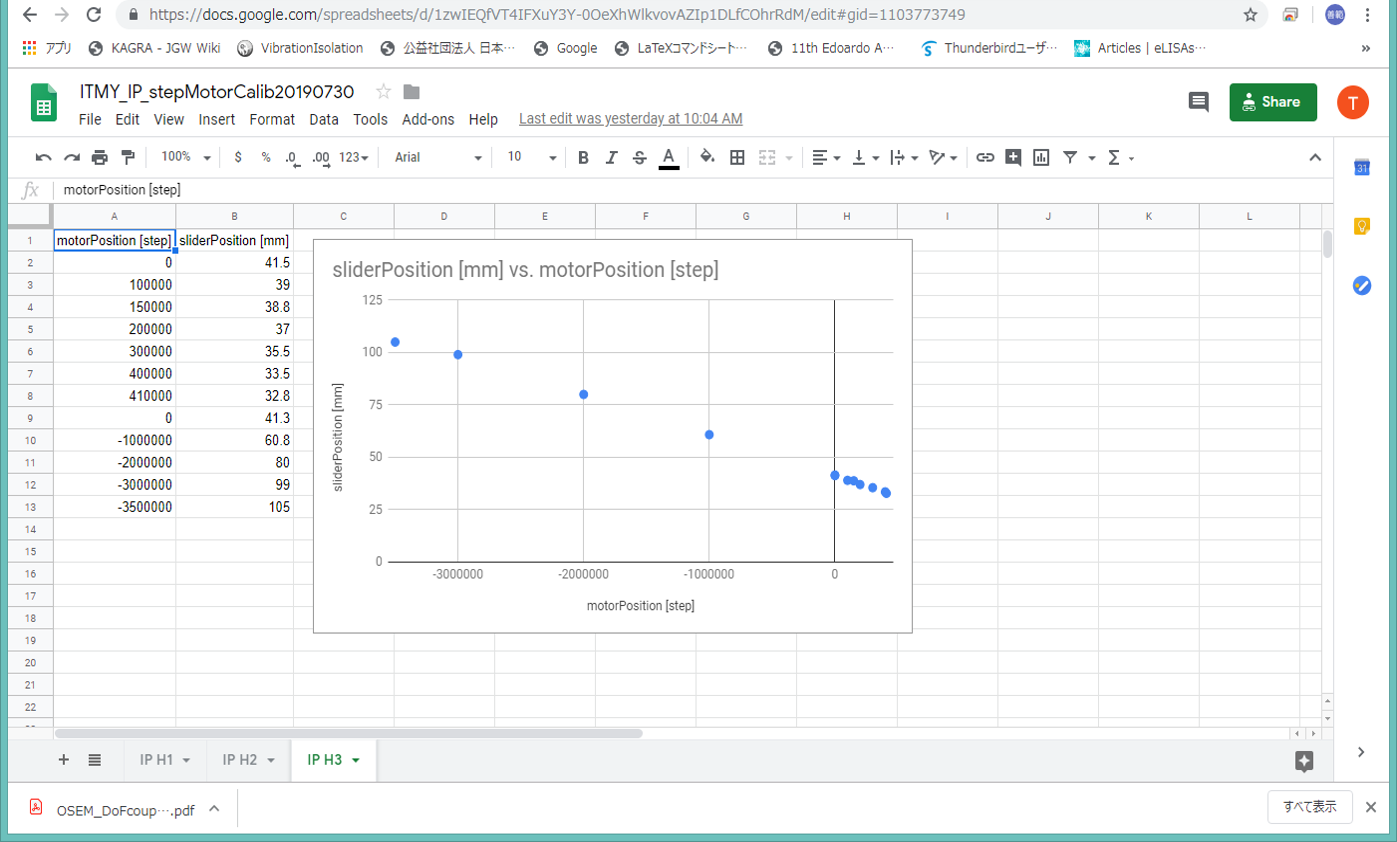
Then we tried to center the IP with the motorized sliders. L and T can be zeroed, but Y was difficult to zero, because it will require one of the sliders to be very close to the edge of the moving range. We decided to forget about putting Y to zero, because we can adjust Yaw with the stepper motor. IP legs tend to have their own confortable equilibrium points. Even if that position creates a large Yaw signal in the LVDTs, we don't care, as long as LVDTs are not close to saturation. We only need to put L and T zero.
The current set points for the IP control are: L = 100, T=200, Y=-710
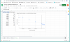
#L=100 and T=200 comes from when Fujii-kun searched for an IP position which makes the BF Yaw transfer function better
After releasing the IP, we tried to recover the mirror alignment with OpLev.
Along the way, we found that the weight of the cryo-payload changed from the addition of the wire clamp, causing the change of the GAS DC positions. CRY people adjusted the weight with ballast masses also adjusting pitch.
Finally, we adjusted Yaw with the F0 Yaw stepper motor and fine adjusted Pitch with the moving masses.
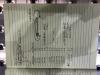
After the OpLev is back to the reference point for the alignment, we removed the aluminum foil to block the beam into the IYC chamber.
Voila !! The Michelson flinge was there !
We confirmed that the alignment was roughly OK. We called it a day.