Reports 1-1 of 1 Clear search Modify search
VIS (SR3)
terrence.tsang - 11:31 Wednesday 10 July 2019 (9456) Print this report
SR3 residual motion

With Fabian,

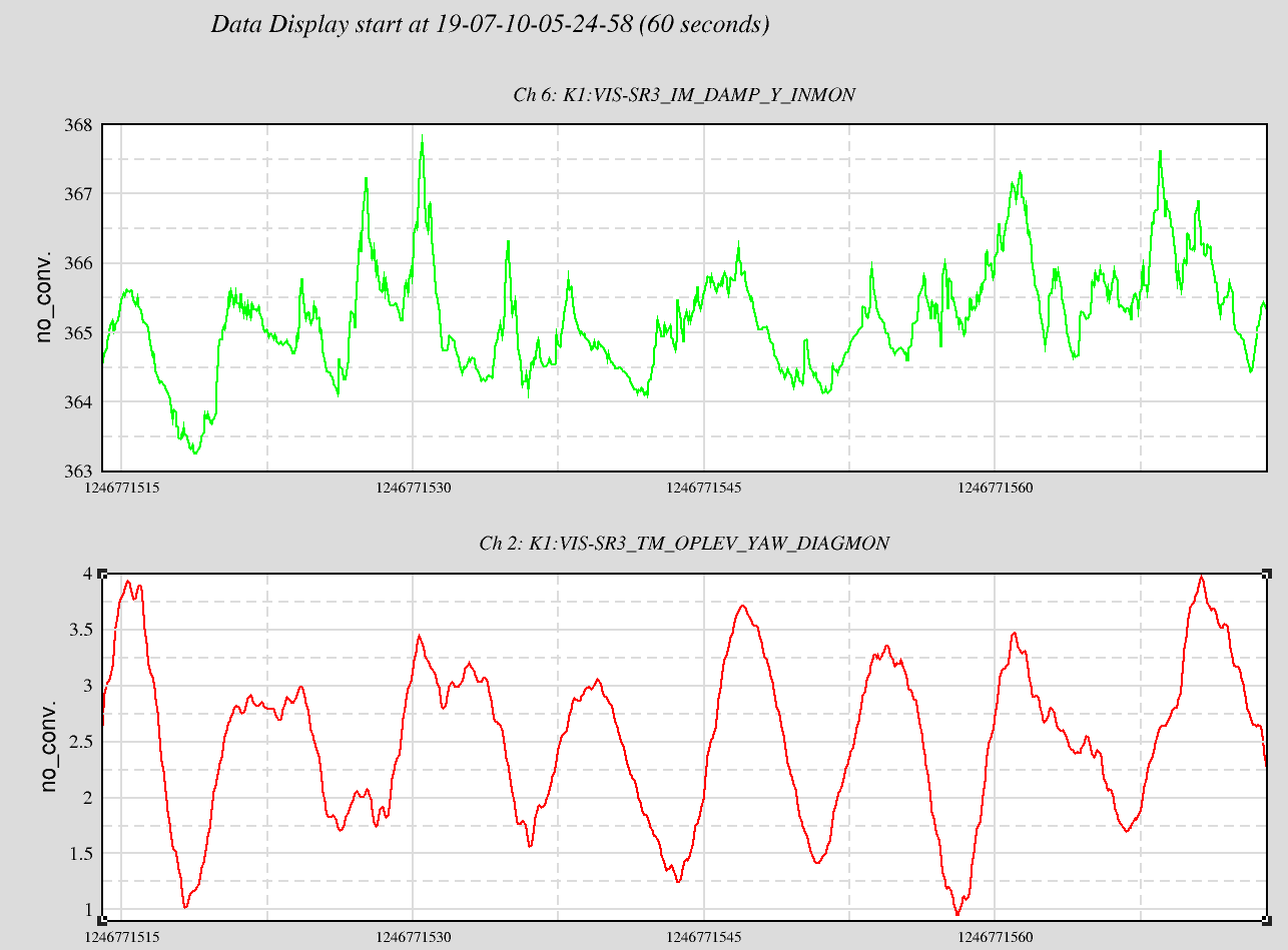
The SR3 hadn't had an optical lever windshield for past period and could potentially jeopardize the lock of the DRMI because the residual motion and TM damping was not properly studied. Therefore, Fabian and I decided to put on a windshield on the SR3 OL. After that I measured the spectrum of the TM motion to confirm that the diaognalization matrix is still good.

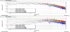
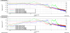
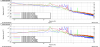
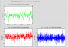
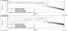
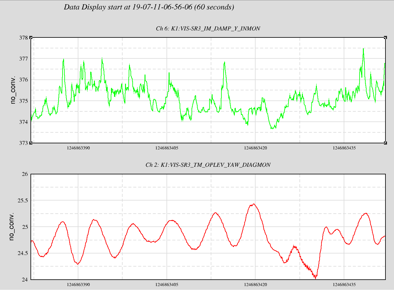
I measured the residual motion before putting on the windshied and after. See figure 1 and 2. The measurements were done with all damping filters on.

Comparing the two results, we can clearly see suppression in L and P. But not so much in Y.  The yaw residual displacment is dominated by motion/noise from 0.14 - 0.2 Hz. I tried implementing TM damping filter to reduce that motion but failed. I am clueless at the moment and I don't know how to further reduce suppress that motion in a short period.

Nevertheless, the measurements confirm that the SR3 satisfies the residual displacement and velocity requirement.

residual displacement (Lock-acqusition and Observation phase)
  Requirement Result
Longitudinal 0.4 µm 0.292µm
Pitch 1 µrad 0.164 µrad
Yaw 1 µrad 0.733 µrad


residual velocity (Lock-acqusition and Observation phase)
  Requirement Result  
Longitudinal 0.5 µm/s 0.347 µm/s
Pitch / 0.417 µrad/s
Yaw/ / 0.941 µrad/s
Images attached to this report
Comments to this report:
terrence.tsang - 15:53 Wednesday 10 July 2019 (9461) Print this report

For reference.

I did the same as 9459 to measure the residual motion of SR3 in both amplitude spectrum and time series while the optic is in the "ALIGNED" state. The amplitude spectrum measured is more or less the same as before. From the time series, the peak-to-peak amplitudes are 2.9 µm, 1.1 µrad and 6 µrad for longitudinal, pitch and yaw respectively. The peak-to-peak value for yaw is probably too large and further suppression is requried. As a comparison, I also measrued the amplitude spectrum earlier today when the SR3 is in the "SAFE" state with the OL within the linear range. see figure 3. As can be seen, the residual motion of SR3 TM yaw while undamped is suprisinly lower and the dominating motion is at around 0.16 Hz instead of the 0.14 Hz. We can see that motion at the longitudinal channel as well. The 0.16 Hz motion coincides with the micro-seismic motion and is not any eigenmode of the suspension. Therefore, I suspect that this motion is due to the excitation to the IP from the ground motion. This situation is very similar to that in 9235, where one of the IP yaw mode is excited by the ground motion. Still, it remains a puzzle to me why this ground motion is coupled to yaw. A possible solution for this is to implement a better damping at the IP stage. However, the geophones for the SR3 at the IP stage are suspiciously noiser than the others and implementing inertial damping to damp the ground motion could be tricky.

Images attached to this comment
fabian.arellano - 10:50 Thursday 11 July 2019 (9490) Print this report

It's worth pointing out that according to the rigid body model of the suspension there are resonant modes at 0.147 Hz and 0.171 Hz. The DoF involved are IM-Y, TM-Y and RM-Y and move always in the same direction with similar amplitudes. The model was tuned to SR2 to a certain exent.

terrence.tsang - 16:23 Thursday 11 July 2019 (9494) Print this report

with Fabian

To study this residual motion, I plotted the time series of both IM yaw and TM yaw and I discovered strange behavior in the IM Y. Basically, what I discovered is that there were fast transients in the IM Y channel. When that happens, the TM Y is kicked by the IM local control and starts to oscillate. This was why one of the yaw mode was continuously being excited. See figure 1 for reference. I decided to turn off the IM yaw local control and the TM Y oscillation reduced from ~4 µrad peak-to-peak (figure 1) to ~1 µrad (figure 2). I also measured the same residual motion in amplitude spectrum and in time series again as a comparison to yestarday's plot. see figure 3 and figure 4. The yaw rms displacement decreased to the 0.3 µrad level and velocity to 0.2 µrad/s level so there is clearly improvement in residual motion despite a clear peak at 0.14 Hz can still be observed. From the 10 minutes time series, peak-to-peak yaw amplitude is around 2.5 µrad as opposed to yestarday's 6 µrad.

Fabian discovered that the the IM H2 is way more noiser than the IM H3 and the cause of this issue is to be investigated.

Enomoto-san pointed out that the IM2TM OL DC yaw control might be marginally stable and that could further worsen the situation. So, I measured IMY to TMY transfer function and carefully design the filter again to make sure that there is enough phase margin at 0.14 Hz. This lowered the rising time of the control so it takes much longer for the TM for be aligned.


Images attached to this comment
Search Help
×

Warning

×