With Enzo, Hirata-san and Fabian.
Today:
- We locked the F0 keystone at 16.5 mm (CAD height) and checked some more vertical height measurements. We concluded that, like the SR2 and SR3, the chain is longer than the CAD by about 7 mm, mostly between the SF and BF. To partially correct this, we chose a keystone height of 11.5 mm (as for SR2) which is 5 mm above CAD.
- The new height can be achieved with about 2 kg on the F0 keystone. Cables have already been added, and we need 1 kg of allowance for a new yaw stepper, so we need to put about 1 kg more on the SF.
- We locked the keystone at 11.5 mm for the next steps.
- We removed the clamps and pins holding the security structure to the assembly frame at the IM level, raised the PI by 3/6 of a turn of the jacks, and removed the IM ring adapter bars, so the security structure was well clear of the frame.
- We removed a cable tie from one IP leg (Fabian had already removed two earlier).
- We unlocked the IP and checked the centering (with no arc weights or geophones for now). As expected from measurements of the IP feet made on 11/15, the IP wanted to move towards the leg at 7:30. (The foot of that leg is welded sticking out 2 mm more (3.3 mm total) from the PI baseplate than the other two, so initial installation leaves the baseplate level and that foot low.) We got good centering by raising the leg at 7:30 about a turn on the jack, and then also raising the leg at 3 o'clock by a small amount.
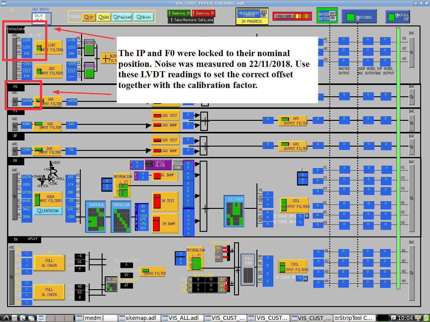
- We checked the IP LVDT coil gaps and set them to 12 mm.
- We manually applied maximum IP yaw (LVDT gap ≈21 mm).
- H1 and H3 were backwards, so we reversed the connections to pins 2 and 7. H2 was unreliable, but we were able to fix it by recrimping two pins closer to the tips. (We also put in a new Type 1 cable for H2, but we're not sure if that helped.)
- Fabian set the phase and gain of the IP LVDT driver channels.
- We manually applied maximum negative yaw (LVDT gap ≈2 mm) and checked that the LVDT readout was still in range.
- We set the coil gap to values in the range 4 mm to 20 mm and took calibration data - see forthcoming klog by Fabian.
- We used a stick of magnets as a probe to check that the IP actuation magnets were properly installed. However we were unable to check the actuation sign because we need to get an extra HPCD.