Reports 1-1 of 1 Clear search Modify search
VIS (IY)
lucia.trozzo - 21:34 Tuesday 02 October 2018 (6383) Print this report
Strange noise on the GAS Filter LVDTs and IP LVDTs: Investigation

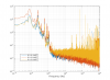
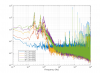
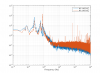
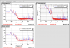
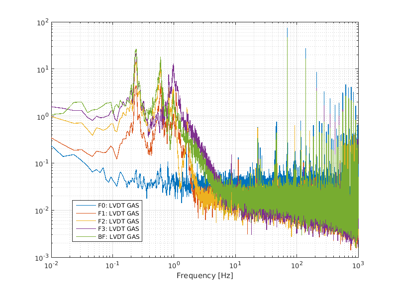
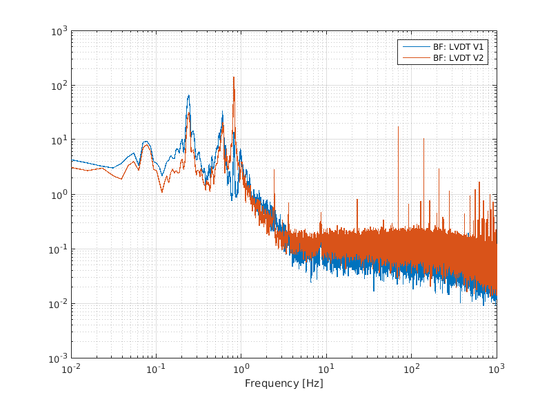
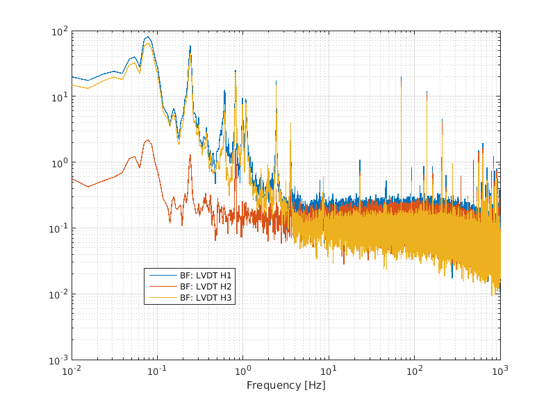
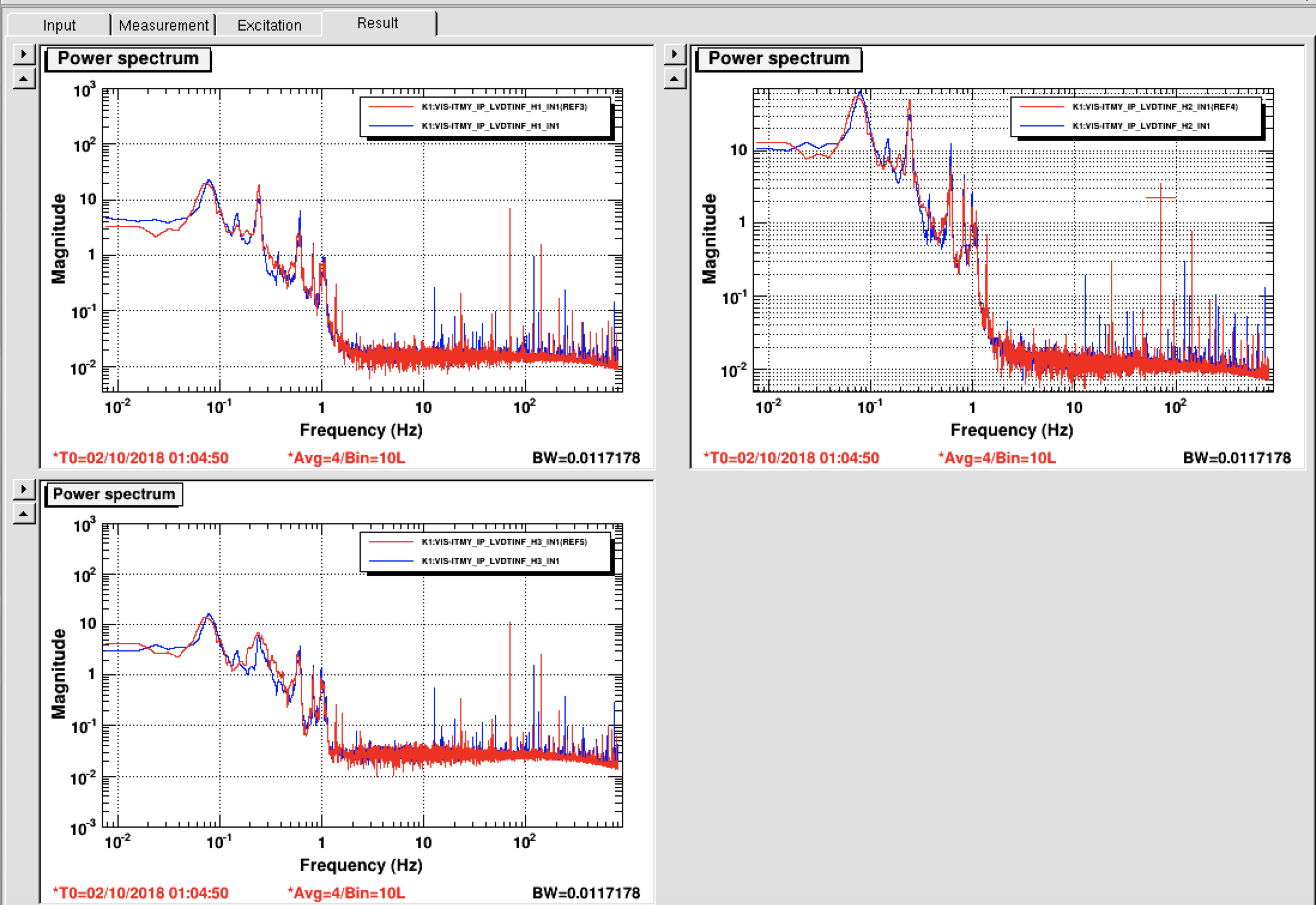
Last week I started to work on ITMY suspension control. Unfortunately, looking at the LVDT signals of the IP and also of the GAS filters I noticed that these were very noisy (a lot of big  and very close lines between 20 Hz up to 1 Khz ) [Fig1, Fig2] .The same noise was not present on the LVDT of the bottom filter (Fig3, Fig4)
Assuming that the problem was connected to the lvdt electronic boards (driving and distribution box), yesterday, I did some tests:
1) I changed the lVDT driving board (I asked Mark to use that one of SRM)
2) I changed the power cable;
3) I changed the distribution box (I asked Mark to use that one of SRM).
At the end of each test the situation did not change: the noise on the LVDTs of IP and GAS filters was the same.
 I can  conclude that the problem is not connected to the lvdt driver and the distribution box.  Probably the lines (in the range [20 Hz, 1 Khz]) could be connected to the digital system: it is necessary to investigate!
 At the end of the tests, I restored   the initial configuration and  I brought  the distribution box and LVDT driver back in the Rec of SRM.


Assuming that the problem was connected to the lvdt electronic boards (driving and distribution box), yesterday, I did some tests:
1) I changed the lVDT driving board (I asked mark to use that one of SRM)
2) I changed the power cable;
3) I changed the distribution box (I asked mark to use that one of SRM).
  At the end of each exchange the situation did not change: the noise on the LVDTs and IP GASs was the same.
At the end of the test, I restored   the initial configuration and  bring back the distribution box and LVDT driver  in the Rec of SRM.
Images attached to this report
Comments to this report:
yoichi.aso - 23:38 Tuesday 02 October 2018 (6388) Print this report

Lucia,

Can you make sure that the observed lines are not aliases of higher frequency ones by looking at the analog signal with an oscilloscope ?

I'd also like to suggest to directly look at the power supply voltage with the oscilloscope to see if the same peaks exist or not.

We have a decent oscilloscope in the rack near the entrance to the MC clean booth.

lucia.trozzo - 19:23 Friday 19 October 2018 (6622) Print this report

Takahashi, Lucia

In order to understand if the origin  of the observed lines are  aliases of higher frequency or not, last Wednesday, we measured the spectra of the LVDTs with the analogue spectrum analyzer. We observed that even in this configuration the noise did not disappear and  we concluded that the problem was not connected with to the  digital system, but perhaps it was connected to the frequency of the demodulation signal (standard 10Khz).
To verify this, we changed the demodulation frequency from 10 Khz to 10.3 Khz. We observed that, by using this new demodulation frequency, the LVDT signals show less noise  and that the 70 Hz line is reduced a lot. We attached here the plot where the comparison of the LVDTs spectra, by using both demodulation signals   (red curve= 10 Khz demodulation, blue curve= 10.3  Khz demodulation,)  are shown.

Images attached to this comment
yoshinori.fujii - 22:24 Friday 19 October 2018 (6625) Print this report

Does this mean we can excite the 2Hz (or 3Hz) line properly, which we were using for the diagonalization work? can you please remind me if you have already confirmed it?

Search Help
×

Warning

×