Masayuki N, Yutaro E, Kiwamu I,
We are done with the LSC electronics check out -- the relevant electronics are ready for the Michelson locking.
Brief review-.
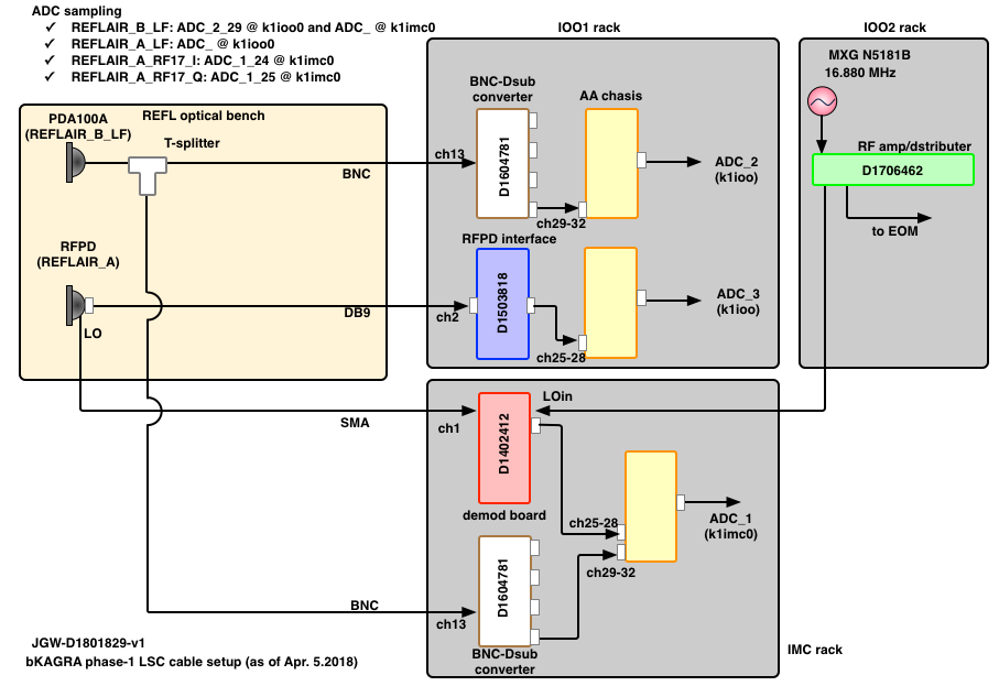
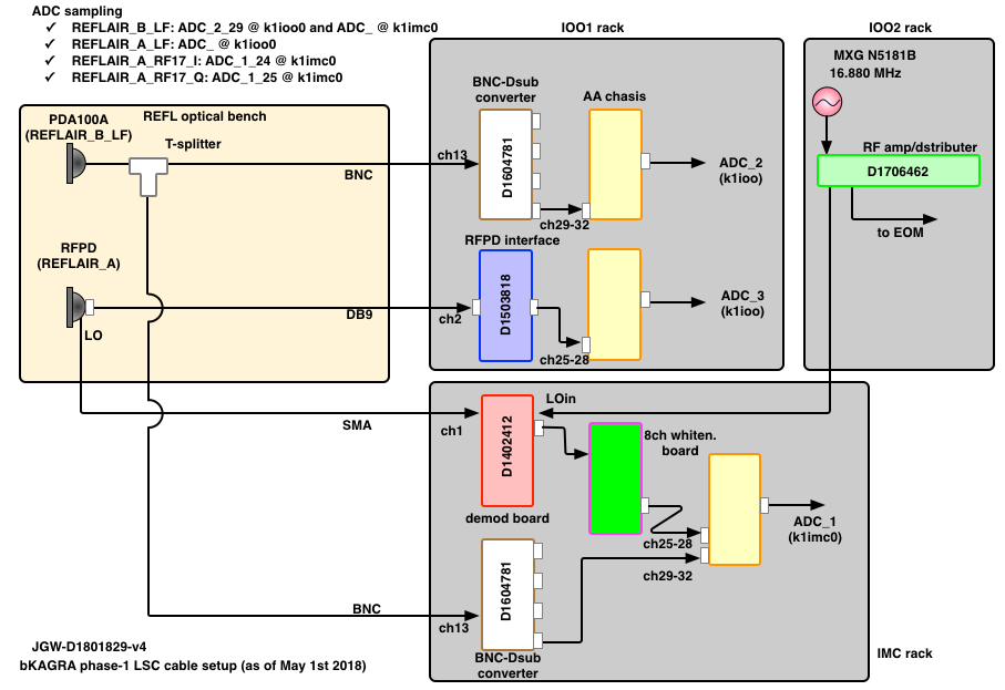
As Enomoto-kun pulled the cables in the last week (4605), we contiuned working on the electronics check-out (4617). The attached is a schematic of the cable layout as of now. The schematic can be obtained from JGW doc at https://gwdoc.icrr.u-tokyo.ac.jp/cgi-bin/private/DocDB/ShowDocument?docid=8129. I believe that most of the cables will be removed once we conclude the phase 1 observing run.
Demodulation board-.
Today or on the 4th, we checked out the RF demodulator which was in the IMC rack for the f1 demodulation at 16.880 MHz. We brought an extra oscillator and hooked it up to the RF input of the demodulation board. The frequency of the oscillator was intentionally shifted from the nominal of 16.880 MHz by 100 Hz such that it results in oscillatory signals at 100 Hz after the demodulation. The local oscillator signal has been provided by an MXG oscillator in the IOO rack.
We measured the LO power to be 12.2 dBm using an oscilloscope. We probably want a 2 dB attenuator for this path because this power is higher than the nominal value of 10 dBm for the demodulation board. Anyway, we didn't change the power for today.
Subsequently, we adjusted the amplitude and phase balances in the LSC realtime digital system using the d-phase and individual gains. They were found to be off by 3 % in amplitude and 1 deg in phase. So the electronics seemed in a good shape. The correction numbers are already typed into EPICS.
Things to be done next-.
- FIne alignment of the RFPD
- Locking the Michelson!


