[Ushiba, Hirose, Kataoka, Sugioka]
Abstract:
We performed adjustments for SRMI 1f and 3f. SRMI1f adjustments were conducted in the same way as PRMI(klog 37812).
Then SRMI3f lock was achieved by copying the control conditions from that of 1f.
Details:
SRMI 1f
We achieved SRMI 1f locking,and completed the phasing, decoupling, calibration, and UGF adjustments for SRMI 1f.
First, we performed the phasing and gain adjustment for SRX(Figure.1).
We changed ELP500 filter to ELP100 in order to avoid the output signal saturation, and SRX was succesfully locked.
Next, we locked SRMI 1f and performed the phasing for POP17 by injecting a 110.125 Hz excitation into K1:LSC-SRCL1_EXC.
We tuned the demodulation phase to minimize the peak in POP17Q(Figure.2).
Then, we addressed the decoupling between SRCL and MICH. These channels exhibit an inherent MICH-to-SRCL actuator coupling.
This cloupling is originated from using only BS as the MICH actuator, since moving BS inherently causes fluctuations in SRCL as well.
To eliminate this fundamental actuator coupling, we decoupled the actuators by adjusting the output matrix.
The value to be set in K1:LSC-OUTPUT_MTRX_6_1 represents the ratio of the SRCL length fluctuations caused by BS versus SRM. The actuator efficiencies were measured by taking transfer functions from excitations of SRM and BS to the SRX length with SRX locked(Figure.3). Since the difference between these responses was -6.586 dB, a value of 0.23479—accounting for an additional factor of 2 due to the difference in the BS position's impact on SRCL and SRY—was entered into K1:LSC-OUTPUT_MTRX_6_1.
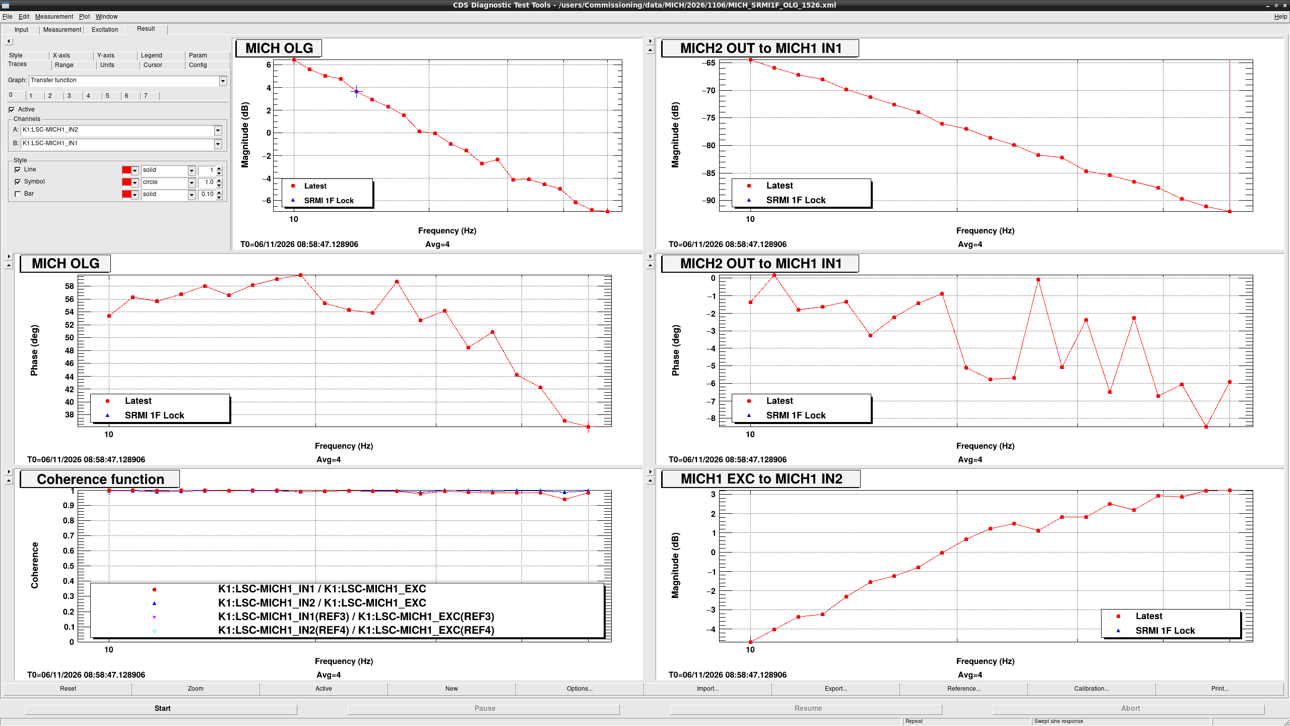
We then performed OLTF measurements for calibration and UGF adjustments. Sensor calibration was conducted while monitoring the Out-to-In TF, whereas UGF adjustments were made by monitoring the OLTFs, for both MICH and SRCL(Figure.4,5). During the sensor calibration, we updated the INMTRX values and simultaneously adjusted the filter gains to maintain the overall control gain. For the UGF adjustment, we fine-tuned the filter gains,resulting in a UGF of ~20 Hz for MICH and ~40 Hz for SRCL.
SRMI 3f
For SRMI 3f, we performed the phasing for REFL51 while SRCL1f was locked(Figure.6), and we copied the control conditions from SRMI1f.
We measured the TF from POP17I/Q-to-REFL51I/Q while exciting SRCL/MICH at 110.125Hz(Figure.7,8).
Then we multiplied the inverse of TF gain to 1f-INMTRX in order to make the 3f-INMTRX.
Measured TF gain for I/Q was -14.374dB/-9.735dB, so we set 3f-INMTRX for SRCL/MICH 66.976/176.4 while 1f-INMTRX was 13.335/57.5.
We put -1 gain filter in MICH1 FM2 because the phase of TF POP17Q2REFL51Q was ~180degree.
Since the control condition for 3f is exactly the same as that of 1f, SRMI 3f control was achieved and OLTF measurement matched to that of 1f very well(FIgure.9,10).
All of these parameter changes were updated in Guardian,and the specific Guardian modifications will be detailed in Hirose-san’s upcoming post.