[Tanaka, Komori, Fujimoto]
Abstract
We measured the PRX length using the TOF technique with the PRMI in the carrier-resonant configuration.
An unexplained 180-deg flip was observed in the measured optimal demodulation phase.
Although the origin of this flip is still unknown, assuming and correcting for this 180-deg offset gives the following result, which is consistent with the measurement by Saito-kun:
- L_{PRX} (this measurement): 68.254(13) m
- L_{PRX} (Saito-kun’s result: klog #37260): 68.26307(11) m
- L_{PRX} (design value): 68.2563 m
Details
In the previous PRX measurement using the TOF method (klog #37244), the PRMI was operated in a configuration where the carrier was anti-resonant and the f2 sidebands were resonant.
In this configuration, if the f2 modulation frequency deviates from an integer multiple of the PRCL FSR, the upper and lower f2 sidebands become detuned from the PRCL resonance.
This detuning rotates the demodulation phase and therefore introduces a systematic error in the TOF measurement.
To avoid this effect, we changed the PRMI configuration such that the carrier was resonant and the f2 sidebands were anti-resonant, and measured the PRX length using the TOF technique.
Modifying the VERTEX guardian for carrier-resonant PRMI
We modified the PRMI_1F_LOCKED state of the VERTEX guardian so that the PRMI could be locked in the carrier-resonant configuration.
The following changes were made:
- The sign of the PRCL gain was flipped.
- The magnitudes of the PRCL and MICH gains were adjusted.
- The lock check for PRMI_1F_LOCKED was changed to POP DC.
Fig. 1 shows screenshots of the lock behavior and the filter settings.
Optimal demodulation phase for carrier-resonant PRMI
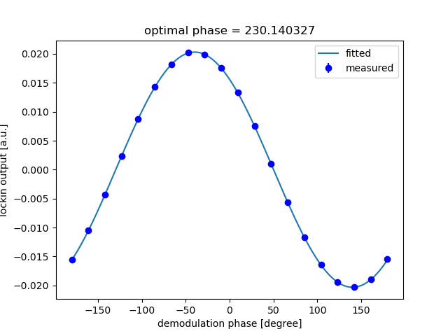
We measured the optimal demodulation phase of the carrier-resonant PRMI using the same code as in the previous measurement with the sideband-resonant PRMI (klog #37244).
The PD used for the measurement was REFL PDA3 45.
Fig. 2 shows the measurement result. The obtained optimal demodulation phase was
- Optimal phase for carrier-resonant PRMI: 225.8(14) deg
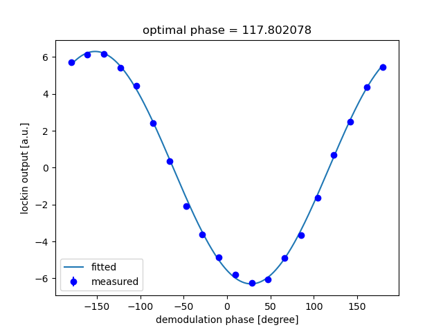
For reference, the results from the previous sideband-resonant measurement are also listed below:
- Optimal phase for sideband-resonant PRMI: 117.80(52) deg
- Optimal phase for XARM: 230.140(48) deg
Data analysis and resulting PRX length
Let the optimal local oscillator for the carrier-resonant PRMI be
where is the optimal demodulation phase.
The optimal local oscillator for XARM is then
so that the optimal phase changes by the phase accumulated over the PRX round-trip length.
In this measurement,
and
Taking into account the current f2 modulation frequency: f2=8*5.624365513 MHz, and the design PRX length L_PRX=68.2563 m, we expect
However, the measured result differs from this expectation by approximately 180 deg.
This discrepancy is much too large to be explained by an actual cavity-length error.
Furthermore, introducing an additional 180-deg correction makes the measurement agree well with the design value.
Therefore, it appears that an unexplained 180-deg phase flip is present somewhere in the measurement.
A Finesse simulation is discussed later in this klog, but the origin of this 180-deg flip could not be identified in the simulation either.
*In the following analysis, we therefore assume that an additional 180-deg phase flip is present for some unknown reason.
With this assumption,
which gives
Comparison with other results
The obtained PRX length is compared with the design value and Saito-kun’s result below:
- L_{PRX} (this measurement): 68.254(13) m
- L_{PRX} (Saito-kun’s result: klog #37260): 68.26307(11) m
- L_{PRX} (design value): 68.2563 m
These results are mutually consistent within the measurement uncertainties.
Finesse simulation
To investigate the unexplained 180-deg flip observed in this measurement, we first considered the possibility of an error in the analytical calculation.
We therefore simulated the optimal demodulation phases for the PRMI and XARM using Finesse and compared the results.
The design values were used for the cavity lengths and mirror reflectivities, and the current modulation frequency,f2=8*5.624365513 MHz, was used.
For the PRMI simulation, an effective ITM reflectivity of 0.85 was used to account for the birefringence of the ITM substrates.
The results are shown in Fig. 3. In the Finesse model, the RFPD was placed at the position of the EOM. Therefore, the absolute demodulation phases differ from those in the experiment. However, this does not matter here because only the relative phase difference is relevant.
The optimal demodulation phases obtained from the Finesse simulation were:
- XARM: 75.978 deg
- PRMI (carrier resonant): 252.299 deg
- Relative difference: -176.321 deg
Thus, as expected from the analytical calculation, the relative phase difference is approximately 180 deg.
Therefore, it is still unclear why the experimental result appears to contain an additional 180-deg flip.
In addition, the PRX length calculated from the relative phase obtained in the simulation is 68.2597 m, which differs by approximately 3.4 mm from the design value of 68.2563 m used in the simulation.
This difference is likely caused by the demodulation-phase shift arising from the fact that f2 is slightly detuned from the exact anti-resonance condition of the PRMI.
A systematic error of approximately this magnitude is therefore also expected to be present in the experimental result.
Summary and future work
In this TOF measurement using the carrier-resonant PRMI, an unexplained 180-deg phase flip was observed.
After applying a 180-deg correction, however, the resulting PRX length was consistent with Saito-kun’s result.
The precision of this method is much worse than that of Saito-kun’s beat-note measurement using an auxiliary laser.
In addition, applying the TOF method to the SR side is difficult. Therefore, there does not appear to be a strong need to continue this measurement at present.
If we want to further validate this measurement method, performing the same measurement for PRY would be a useful next step.