[Tanaka, Hirose, Saito]
A 10 dB attenuator was added, reducing the beat signal level from 23 dBm to 10 dBm. The open-loop transfer function of the PLL was then measured. The results suggest that the sub-laser PZT responds with a frequency change to the frequency-difference signal from the PFD, rather than responding with a frequency change to a phase-difference signal. In addition, the alignment of the sub-laser beam incident on SRY was performed using two irises. The sub-laser PZT was then driven, but no flashes were observed at the AS port. This is likely because one of the optics expected to be a mirror was actually a BS, the beam was clipping on the edge of a mirror, and the observation was being made at the AS port. In the next experiment, the BS will be replaced with a mirror, the alignment will be redone, and a PD will be installed at the OMC reflection port to observe the flashes.
- First, a 10 dB attenuator was added to reduce the input power to the PFD. As a result, the beat signal level decreased from 23 dBm to 10 dBm. Next, the 1 MHz low-pass filter in the SR560 used for feedback to the sub-laser PZT was replaced with either a 100 kHz or a 10 kHz low-pass filter. Under these conditions, the approximately 260 kHz oscillation previously observed in the error signal (klog:37046) disappeared. The open-loop transfer function was then measured, revealing a flat region. This was unexpected. We had assumed that the feedback loop operated by changing the sub-laser frequency via the PZT to eliminate the phase difference, which should behave as an integrator. However, the observation is consistent with the PFD producing a frequency-difference signal and the sub-laser PZT responding with a frequency change. Therefore, a 10 kHz low-pass filter was applied in the SR560 feedback path to the sub-laser PZT, and the gain and integrator cutoff frequency in Moku:Lab were varied. The measured open-loop transfer function then closely matched the designed filter response (Photo 1).
-
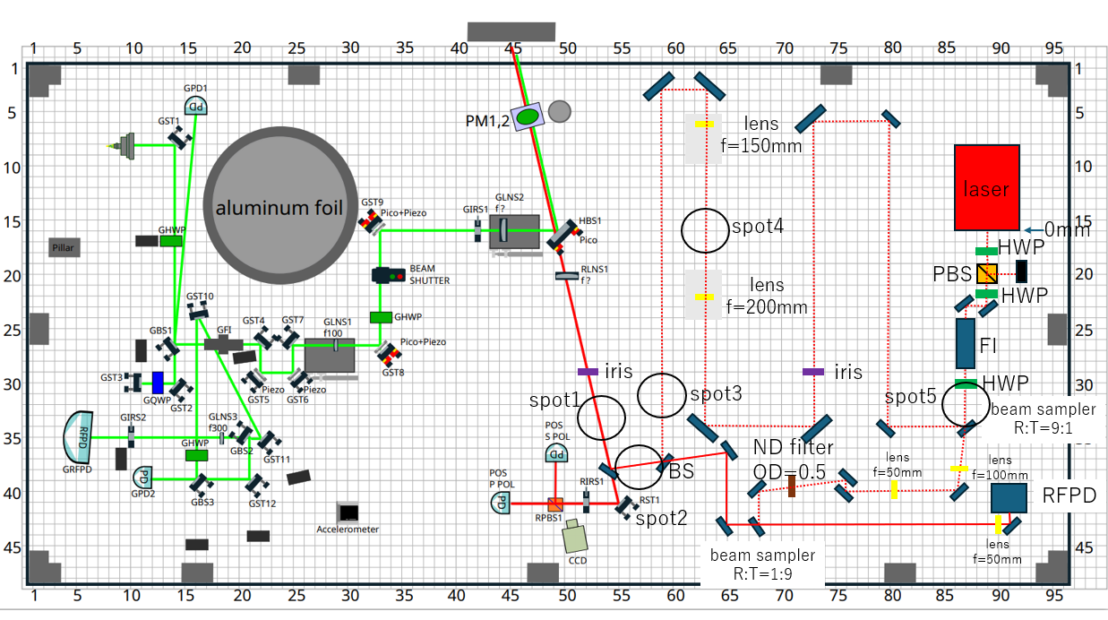
Next, the mirrors were adjusted so that the main laser beam followed the optical path intended for the sub-laser beam entering the interferometer. Two irises were then installed along this path and aligned to the main laser beam. The sub-laser alignment was subsequently adjusted so that it also passed through the two irises. The main laser was then blocked, leaving only the sub-laser beam incident on SRY. The sub-laser PZT was driven with a triangular waveform generated by the Moku:Lab function generator, and the AS port was monitored for flashes. However, no flashes were observed. This is likely because the optical power incident on SRY was too low. The laser powers measured at Spots 1~5 in Photo 2 were as follows:
Spot 1: approximately 130 mW
Spot 2: approximately 390 mW
Spot 3: approximately 780 mW
Spot 4: approximately 1.0 W
Spot 5: approximately 1.1 WFrom these measurements, the laser power incident on SRY is estimated to be approximately 130 mW, which corresponds to only about 0.25 μW at the AS port. Such a small signal is likely buried in noise. The reduction in laser power between Spot 2 and Spot 1 occurred because the optic between them was a BS rather than a mirror. In addition, the reduction in power between Spot 4 and Spot 3 may be due to the beam clipping on the edge of the mirror.
-
Therefore, in the next experiment, the BS between Spot 2 and Spot 1 will be replaced with a mirror, and the alignment will be adjusted so that the beam does not clip on the edge of the mirror between Spot 4 and Spot 3. However, even after these modifications, the power at the AS port is expected to increase only to approximately 0.97 μW. Therefore, a PD will be installed at the OMC reflection port, and flashes will be monitored there instead.

