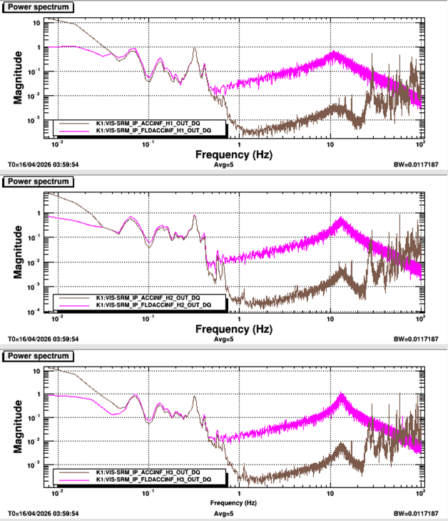
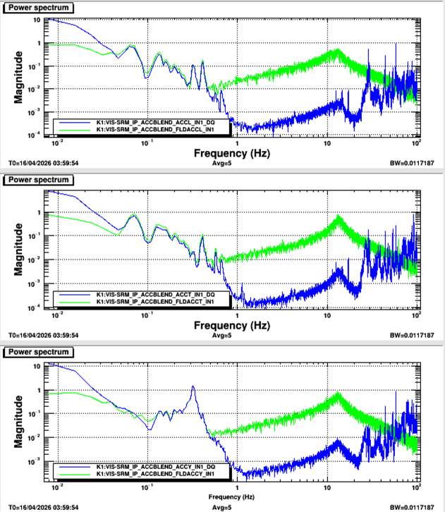
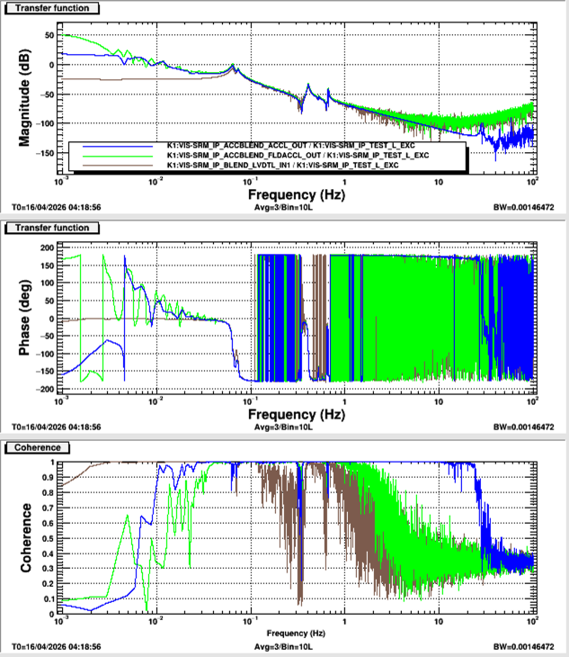
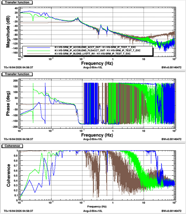
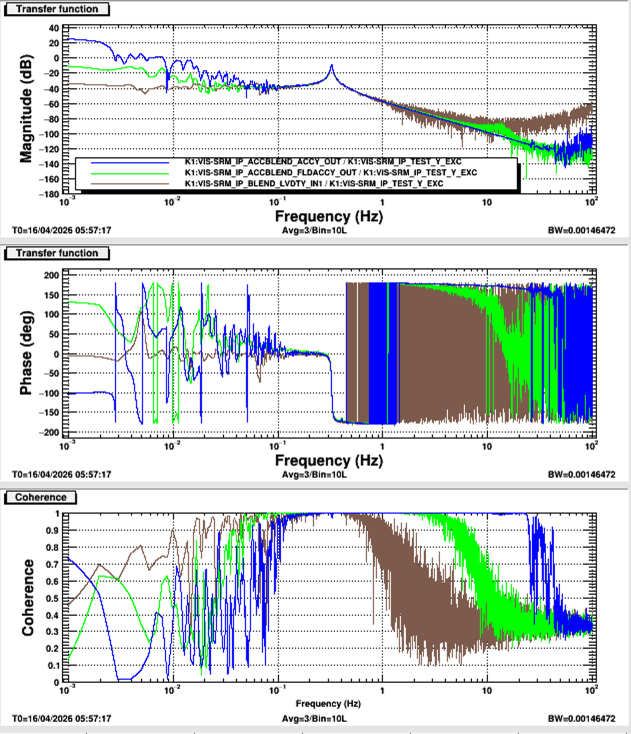
I'm implementing the IP control with the FLDACCs. I tuned the coefficients for each FLDACC relative to ACC (geophone). Plot 1 shows the spectra of each ACC and FLDACC. Plot 2 shows the spectra of each virtual sensor (L, T, and Y). I measured the transfer functions from each virtual actuator to each virtual sensor (Plots 3, 4, and 5). The gains of the ACCs and FLDACCs are increasing toward DC below 70mHz for L and 50mHz for T.


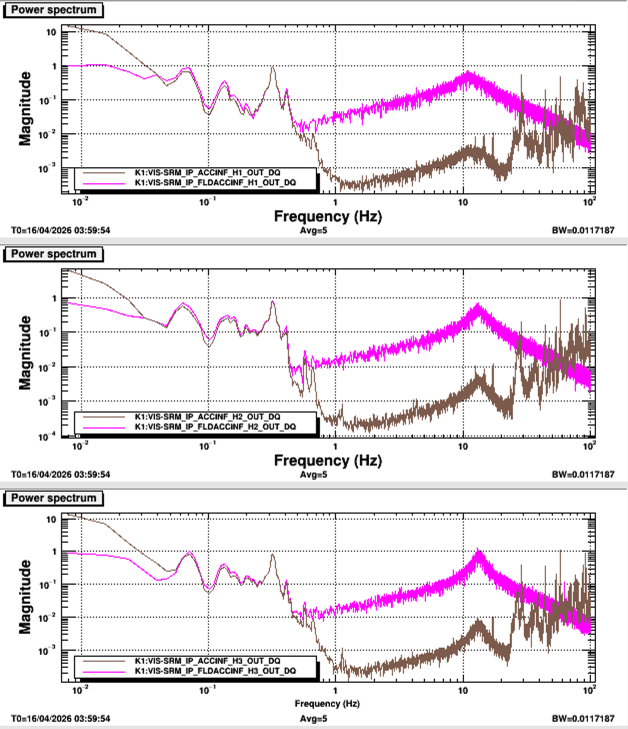
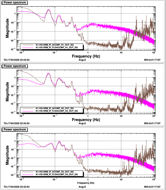
I tuned the servo control for the FLDACCs. The UGF was changed from 10Hz to 1Hz to avoid the induced noise in the ACCs (geophons). Plot 1 shows the spectra of each FLDACC and ACC with the 10Hz UGF. Plot 2 shows the spectra with the 1Hz UGF. The noise floor of the ACCs was reduced.


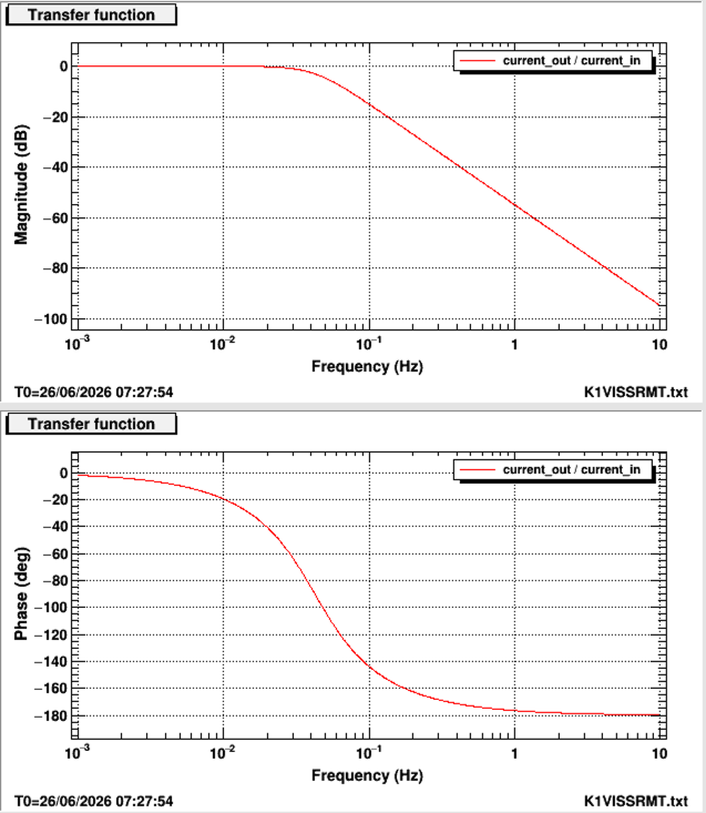
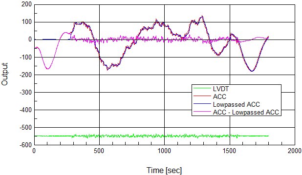
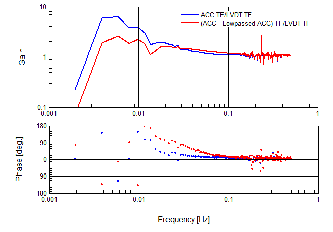
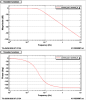
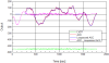
Measured TFs from the IP actuator to the ACCs (or FLDACCs) showed increasing gain toward DC below 70mHz for L and 50mHz for T as reported in klog. It is due to the cradle effect. It is difficult to correct the gain using general servo filters. We are considering whether feedforwarding can reduce the gain at low frequencies. I tried to create ACC L signals compensated by the low-passed signals offline. Plot 1 shows the used low-pass filter. Plot 2 shows time-domain data of LVDT, ACC, and low-passed ACC signals. The IP L was excited with the IP actuator during 300~1500sec. Plot 3 shows the ratio of the LVDT TF and the ACC TF. The gain with compensated signals was smaller than the original, but the phase difference was larger.

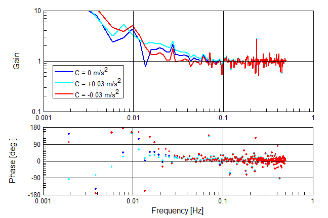
In the last test (klog), I tried to feed forward the low-pass-filtered ACC signals to the original ACC signals in order to compensate the cradle effects. In this time, I tried to feed forward the LVDT signals to the original ACC signals using the same offline data. Assuming that the tilt of the IP table is proportional to the deviation of the IP, the acceleration α due to the tilt φ is expressed as α = g·φ = C·δx. Here, g is the gravity acceleration, C is the coupling efficiency, and δx is the deviation to be obtained from the LVDT signal.
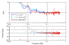
The plot shows the ratio of the measured transfer functions from the actuator L to the LVDT L and the ACC L. The blue line shows the original TF ratio (C = 0 m/s^2 /m). The red line shows a smaller gain deviation (C = -0.03 m/s^2 /m).