[Nakagaki, Ikeda, YamaT]
This is similar work of ITMX (klog#36572) and ITMY (klog#36625).
A preliminary research about a situation of both end stations was reported in klog#36635.
I/O chassis of K1EX0 was replaced from V1 (S1604791) to V2 (S2416131).
The front-end computer was also replaced from V3 to V4, but it hasn't been moved from EX0 rack to EXV1 rack due to a miscommunication about laying MTP cables.
We cannot complete this work until purchasing some cables in April.
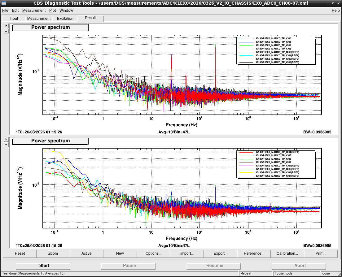
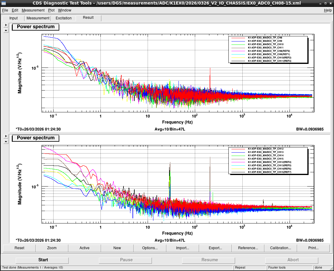
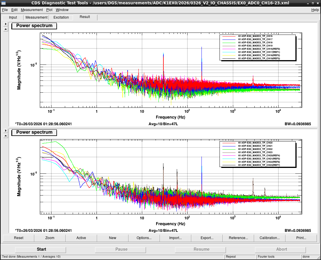
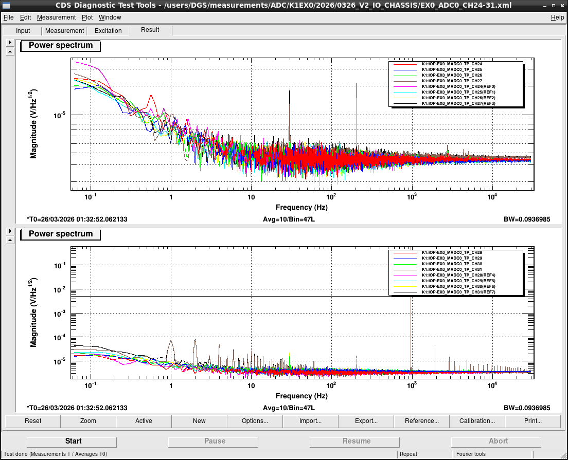
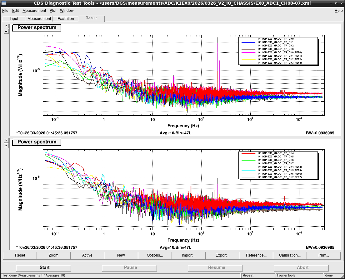
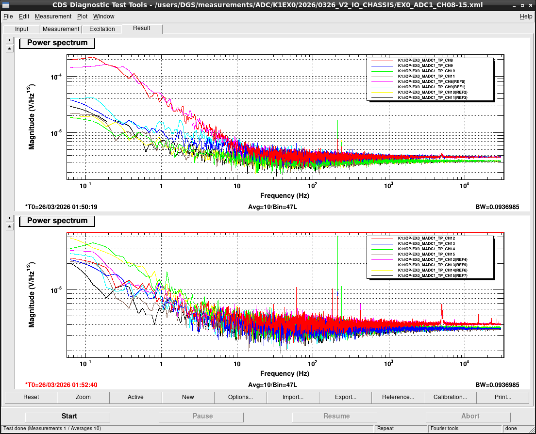
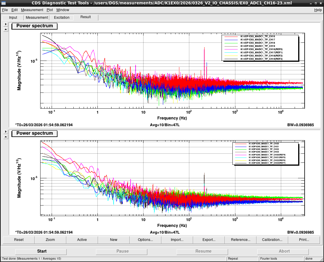
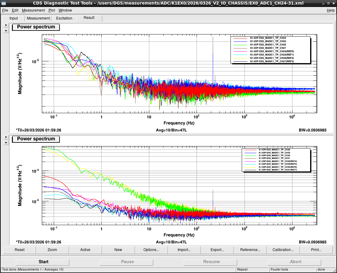
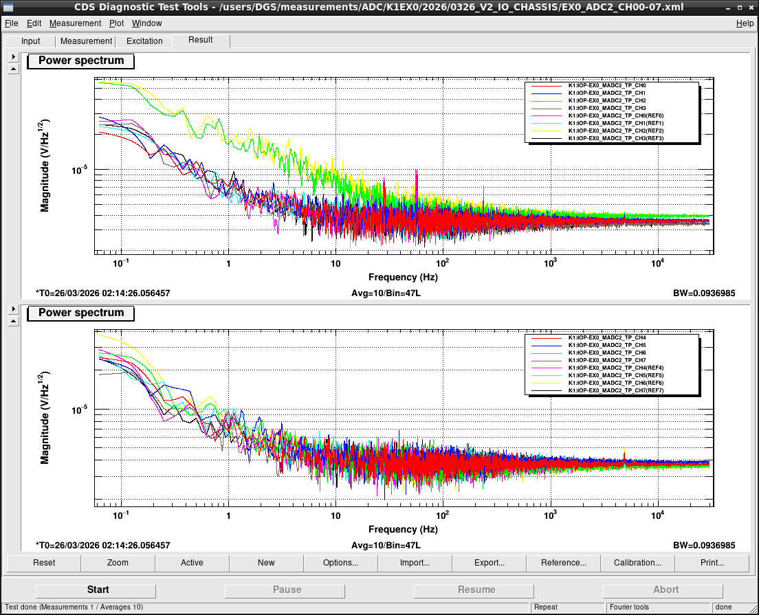
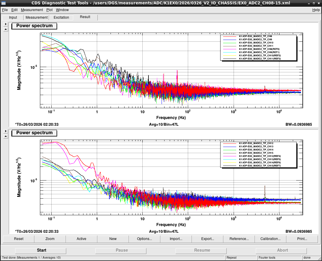
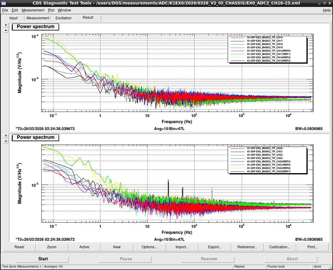
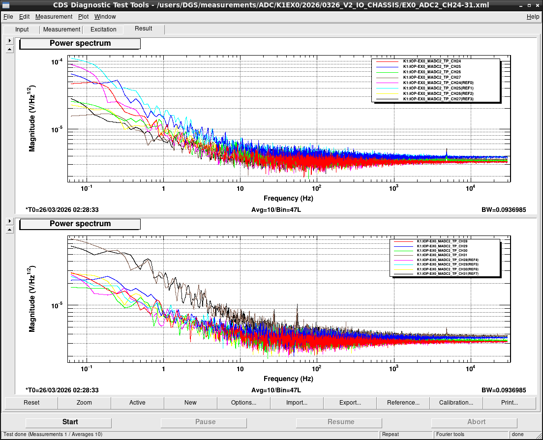
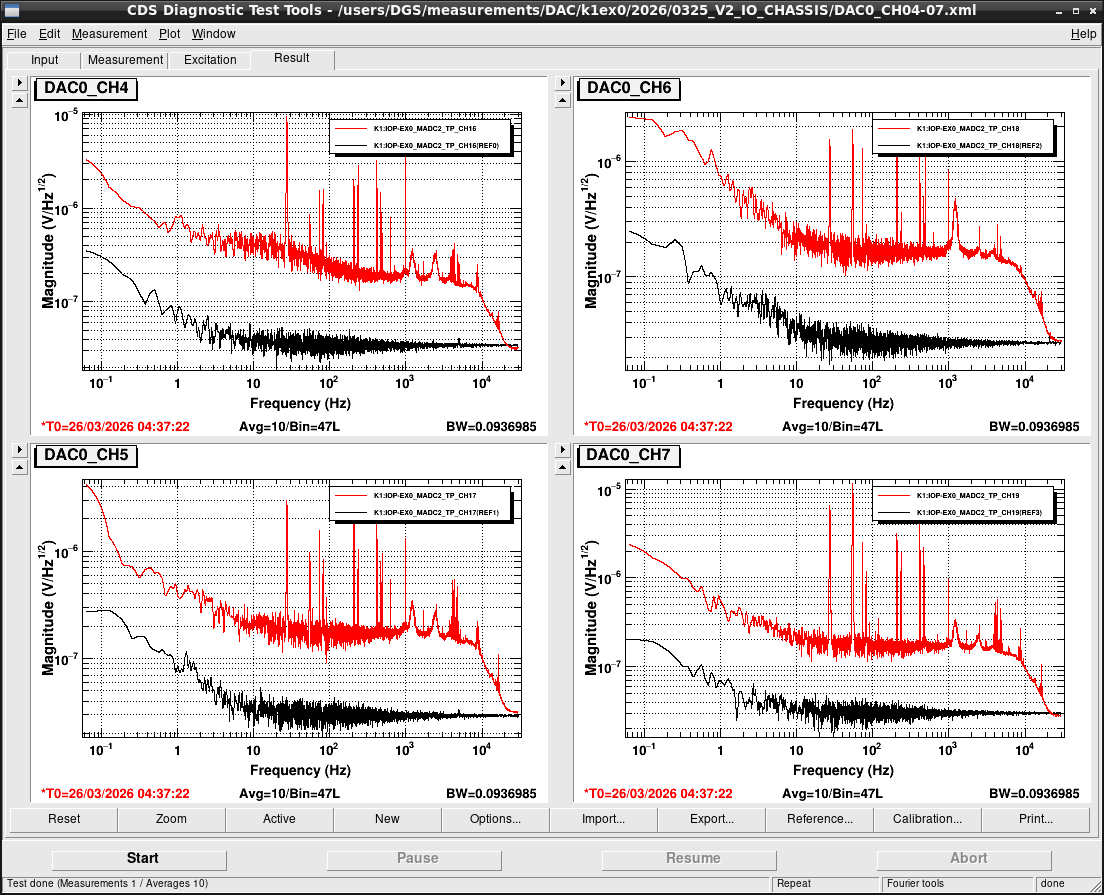
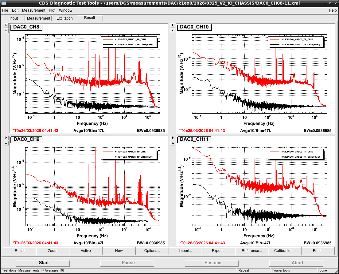
ADC/DAC noise measurement is planned to be done tomorrow.
-----
I/O chassis replacement
We replaced the V1 I/O chassis (S1604791) at U18-21 of EX0 rack as V2 I/O chassis (S2416131). In this time, all PCIe cards were moved from V1 I/O chassis to V2 I/O chassis in stead of preparing V2 I/O chassis in which attached spare PCIe cards. Though this procedure involves a risk of taking long time if we need to restore all due to some trouble with V2 I/O chassis, we determined that’s highly unlikely based on the past experiences. (Besides, there’s also the fact that it’s not realistic to prepare same number of spare cards as one of installed cards.) On the other hand, an advantage of this procedure is S-number of used ADC/DAC boards isn't changed.
Front-end replacement
In the original plan, the front-end computer was planned to be moved from the the EX0 rack (1F) to the EX1 rack (2F) as part of the upgrade from the V3 server to the V4 one. An combination of V2 I/O chassis and V3 server has a limitation about a number of attached PCIe cards and EX0 has many ADC/DAC boards. So replacing V2 I/O chassis at EX0 requires to upgrade also the front-end server. Moving front-end server from the EX0 rack to EX1 rack is the most important advantage of using V2 I/O chassis. Because of specification of the cables for V1 I/O chassis, we couldn't separate the servers from analog electronics in the 1st floor of the end stations. Another concern was the increasing number of daisy-chain segments and growing latency across various networks, including RFM.
For this reason, we tried to install a new V4 server in the EX1 rack at first. But a gender of MTP at the splice box was different from one in the discussion in advance. Because MTP pins are very thin and are easily broken, we designed the entire assembly so that the connector of cables which is wired by ourselves would be female. So MTP of breakout cable we have has female connector. The splice box at EX1 rack has unfortunately also female receptor and we couldn't connect them.
Finally, we gave up to install V4 server in the EX1 rack today and installed it at U13-14 in the EX0 rack after removing the V3 server. So the replacement of I/O chassis and front-end computer were finished but the upgrade task hasn't been completed yet. To proceed it, MTP breakout cables with male connector must be purchased. We can resume this task after April.
Side Note
Some SDF differences on the EX0 models remained.
k1tmsx
All differences are accepted in safe.snap (see also Fig.1)
k1calex
It comes from CAL_EX guardian was in FAULT and was paused. It's related to a shutdonw of laser itself (see also klog#36639). For such case, SAFE state should be defined as allowing to stop a laser output without stopping/pausing. Otherwise, any other maintenance cannot be down while the laser output is stopped. In this time, I manually removed all DAC output, then all values accommodated with the set point in safe.snap.


