Reports 1-1 of 1 Clear search Modify search
VIS (SRM)
ryutaro.takahashi - 16:48 Tuesday 10 February 2026 (36327) Print this report
Preparation for SRM installation

I checked the condition around the SRM chamber.

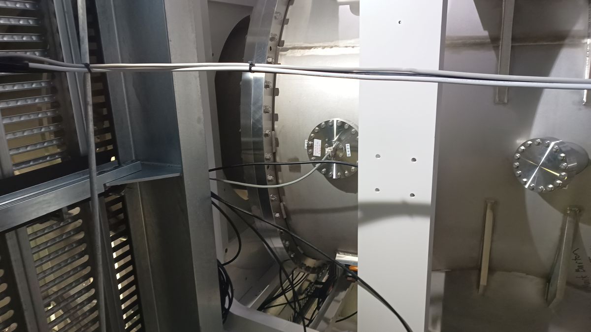
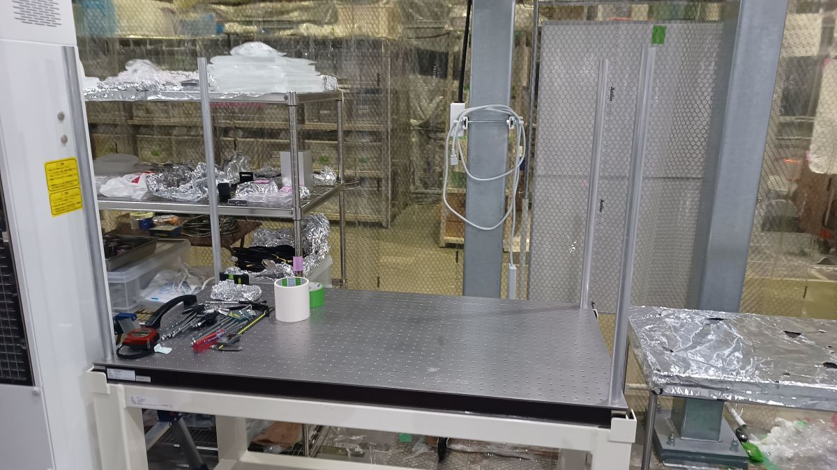
Feedthrough flanges: The D-sub cables were put from the flanges to the cable rack (Picture #1) on the side of the booth.

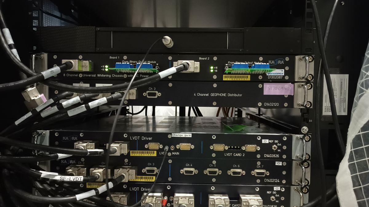
  • ICF203 on the bottom chamber for the IRM damper. The present flange with one D-sub 9pin port will be replaced with the flange with four D-sub 9pin ports (Picture #2).
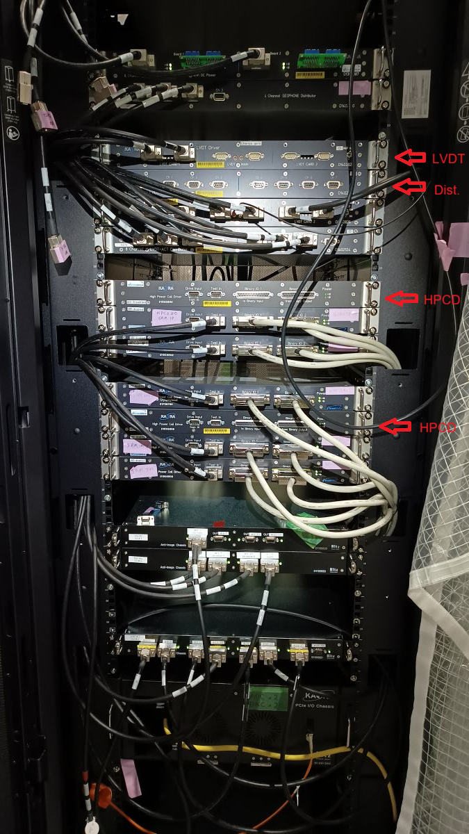
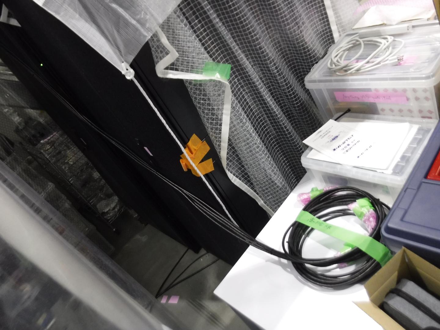
  • ICF203(P6) on the top chamber for the FLDACC H2 (Picture #3).
  • ICF203(P3) on the top chamber for the FLDACC H1 and H3 (Picture #4).

SRM mirror holder: I checked the mirror holder in the decicator for OMC. The holder was assembled with the jig (Pictures #5 and #6).

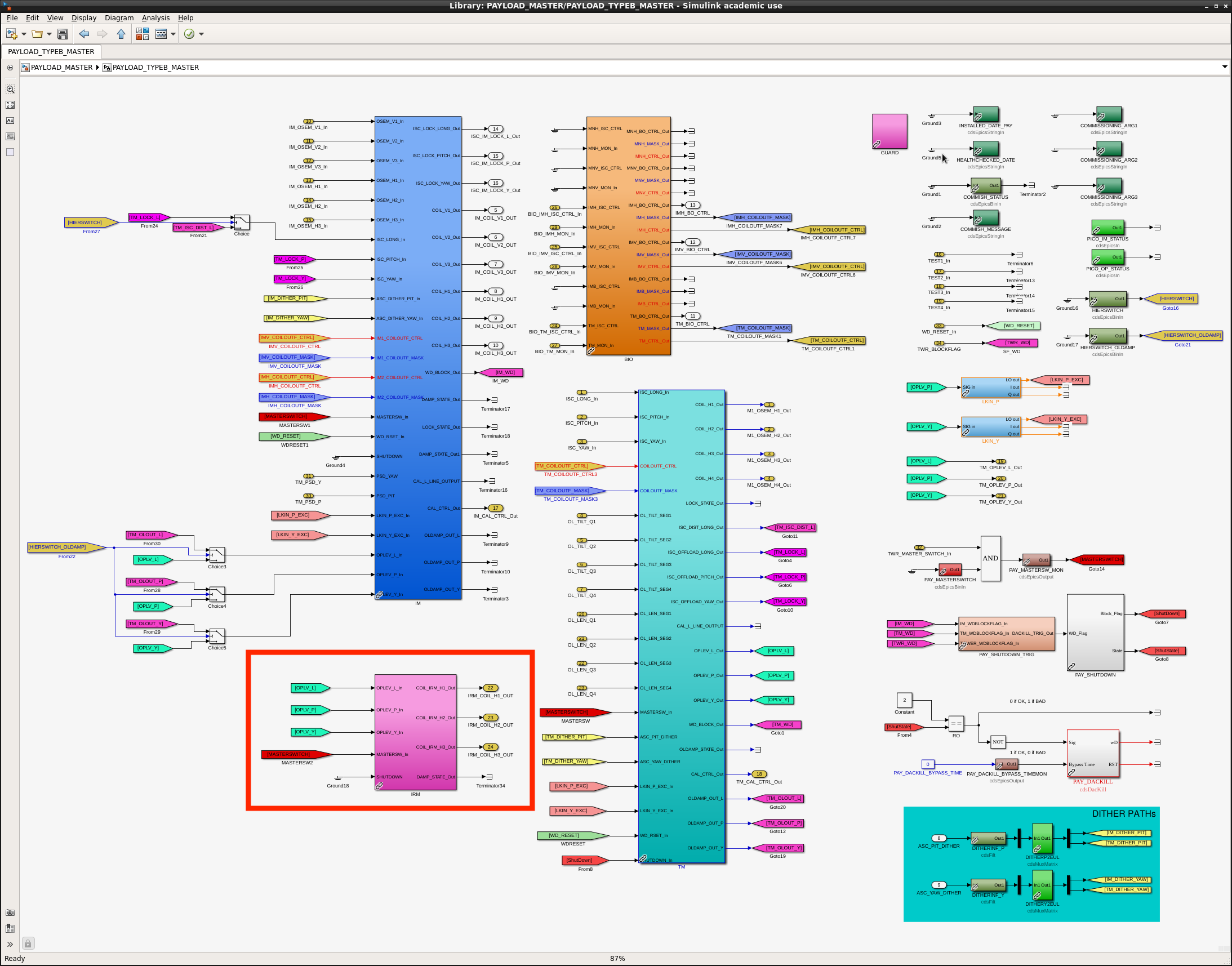
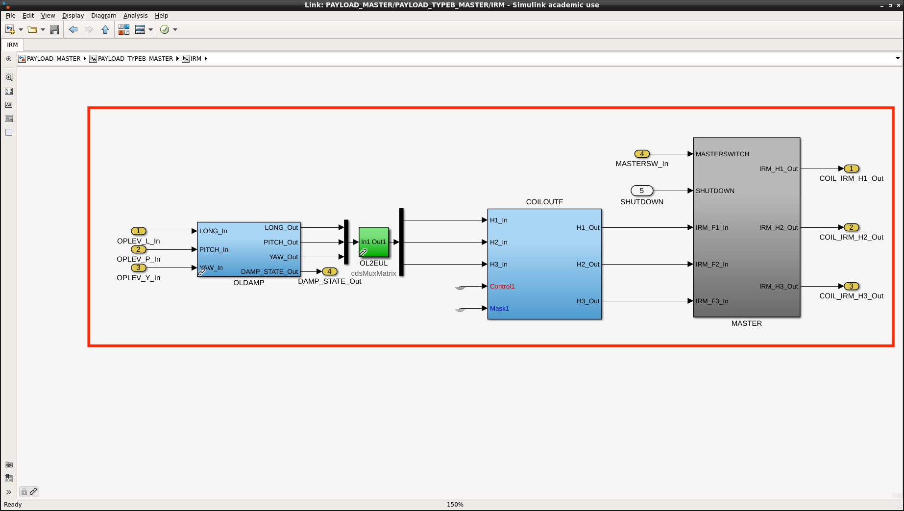
IRM damper: The parts for the IRM damper were delivered and checked in the booth (Picture #7).


Images attached to this report
Comments to this report:
satoru.ikeda - 16:06 Tuesday 17 February 2026 (36374) Print this report

[Ushiba-san, R.Takahashi-san, Ikeda]

Prepared the model files for FLDACC and IRM dampers.
This time, only model editing was performed; make and install have not yet been executed.

Basic Design
Modifications to k1vissrmt.mdl and k1vissrmp.mdl

・First, all elements broken from the common model due to the K-Log#17302 fix were removed. They were changed to use blocks common with other Type-B models.

・k1vissrmt.mdl
 Added input from adc and output to dac to FLDACC.
 Input: adc0_{28,29,30}
 Output: dac1_{8,9,10}

・PAYLOAD_MASTER.mdl
 Copied PAYLOAD_MASTER (shared by Type-B and Bp) and created a new PAYLOAD_TYPEB_MASTER. Added a block for the IRM damper inside it.

・k1vissrmp.mdl
  Replaced with the PAYLOAD_TYPEB_MASTER block and added IRM_COIL output as output to the DAC.
  Output: dac1_{4,5,6}
 

Images attached to this comment
Non-image files attached to this comment
ryutaro.takahashi - 18:37 Tuesday 17 February 2026 (36378) Print this report

[Takahashi, Ikeda]

We installed an LVDT Driver, an LVDT-ACT Distributor, and two High Power Coil Drivers into the SRM rack (Picture #1).

  • LVDT Driver: S1403138 for FLDACC
  • LVDT-ACT Distributor: S1503680 for FLDACC
  • HPCD: S2315291 for FLDACC
  • HPCD: S2315288 for IRM damper

We checked the FLDACCs transported from NAOJ (Mitaka). Unfortunately, the folded pendulum blocks have been broken (Picture #2). Though the proof masses were fixed with the stopper screws and sims, all of the hinges were cut (Pictures #3 and #4). The stopper screws may not be enough to fix the proof mass tightly. It has a high risk to transport assembled FLDACCs. Therefore, the folded pendulum blocks should be assembled at the site. Spare blocks will be sent with the fixing covers that sandwich the block with the piercer bolts.

Images attached to this comment
satoru.ikeda - 10:25 Friday 20 February 2026 (36406) Print this report

Ushiba-san, Ikeda

k1vissrmp.mdl(PAYLOAD_MASTER)
Parts of the model have been updated.
Changed OL2EUL in the IRM block to ACTALIGN and EUL2COIL
Added DAQ channels
 OLDAMP_{L,P,Y}_IN1 1024
 OLDAMP_{L,P,Y}_OUT 256
 MASTER_OUT_{H1,H2,H3} 2048

 FLDACC-related DAQ is already present, so no need to add.

Images attached to this comment
Non-image files attached to this comment
ryutaro.takahashi - 17:57 Thursday 26 February 2026 (36450) Print this report

I started the reassembly of the broken FLDACCs. #4 folded pendulum block was replaced with #7 block (Picture #1), which was transported with the special box (Picture #2) from NAOJ (Mitka). The assembled pendulum looks fine (Picture #3). The FLDACCs for SRM moved to the BS area temporarily to prevent troubles due to the cleaning of the SR-OMC booth (Picture #4).

I installed the poles to cover the table to store the MSBs removed from the SRM chamber (Picture #5).


Images attached to this comment
satoru.ikeda - 11:14 Friday 27 February 2026 (36457) Print this report

Ushiba-san, R.Takahashi-san, Ikeda

The VIS model file described in K-Log#36374 has been installed.

[K1SRM]
 TOWER_MASTER
 PAYLOAD_MASTER
 k1vissrmt
 k1vissrmp
  The file prior to the modification was copied to the archive/ directory (20260216).
  Since the blocks were unified(related to K-Log#18595), resulting in a change in the DAQ data volume.

  DAQ_BYTE_COUNT
  k1vissrmt: 506 -> 398
  k1vissrmp: 422 -> 469
 

Images attached to this comment
Non-image files attached to this comment
ryutaro.takahashi - 15:36 Friday 27 February 2026 (36460) Print this report

I installed the signal generator box for the LVDT driver in the SRM rack (Picture #1). The amplitude of the 10kHz output was set to 7Vp-p. The cables from the SRM chamber (Picture #2) were connected to the LVDT distributor and the coil driver.

Images attached to this comment
Search Help
×

Warning

×