PSL:Uchiyama, Tanaka, remote: Ushiba, Miyakawa
## Abstract
We took over the investigation in klog35365. We perfomed some investigaion (polarization, power, temperature) but we failed to recover the 3rd fiber amp. laser today.
## What we did
### Monitor seed laser output
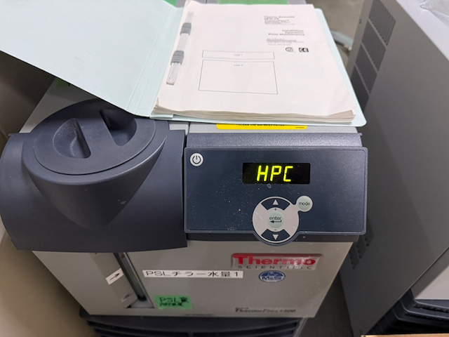
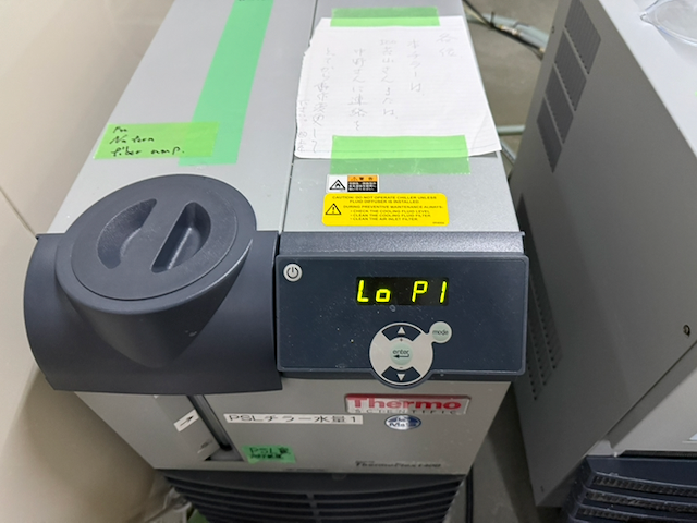
This morinig I heard from Miyakawa-san that the fiber amp. fall down during increasing the output power and then the error massage "Master fault, Seed Power is too low" was poped up in the controller screen. According to p.25-26 in the manual (JGWdoc, need usual password), when the "Seed" value gets less than 1.1 V, the fiber amp. this results low seed power fault. So we checked whether the seed output was stable or not, at first.
As a preparation, we connected a T connecter at the PD output which is used for the interlock and the one port of T connecter was connected to the interlock and the other port was conneceted to DGS to be able to monitor the PD output with DGS. In this time, we used the channel, which was used to monitor a RefCAV trans. power, K1:PSL-REFCAV_TRANS, as the PD output monitor. Also, K1:PSL-REFCAV_TRANS_OUT seems to be calibrated from DGS cnts to V.
Then, we turned on just the seed laser. According to Uchiyama-san, in this early morining, the laser fall down with 7 mins (fig.1). So we monitored the output more than 7 mins. Fig.2 shows the trend of the PD output, K1:PSL-REFCAV_TRANS_OUT. This value at the vertical axis is calibrated to V. In the case of turing on the seed laser, the output is about 2.58V. The amount of the output seems to be fluctuating in +/- several percents. However, the power don't seems to drop down to 0 or the interlock threshold value, 1.1 V within more than 10 mins. Therefore, the seed power at PD seems to be stable enough.
Similarly, we checked whether the actual input power to the fiber amplifier was stable or not. We turned off the seed laser and disconnected the fiber from the input port on the amplifier. We noitced that there seemed to be a small black dot on the edge of the fiber (fig.3). So we cleaned the edge of the fiber with a fiber cleaner (OPTIPOP R2) and then we succeeded in removing the black dot (fig.4). We checked the power before and after cleaning but the power was not changed by the cleaning.
After cleaning the fiber, we connected the fiber to the PD and monitored the actual input power to the amplifier. Fig.5 shows the trend of the input power. The PD output of the input power is ~0.25 V. This is because we used a 90:10 fiber splliter (Thorlabs, PN1064R2A1) and we used the 10% side for the input power. Therefore, the PD output with the input power, 0.25 V is consistent with 1/9 of the PD output power, 2.6/9 =0.289 V in the order. From the result, the input power seems to be also stable within more than 10 mins. So the input power seems to be stable enough.
(Note: we cleaned the other edge of the input fiber. But the situation was not changed.)
### trial of 1 W emission
Secondly, we tried to emit the laser from the fiber amplifier. In this time, any current for the amp. was not applied, that is, we wanted to check the fiber amp. could emit 1W stablely. We turned on the fiber amplifier and emitted the laser from the fiber output. Fig. 6 shows the trend of the PD output for the interlock, corresponding to the input power of the fiber amplifier (K1:PSL-REFCAV_TRANS_OUTPUT) and the fiber output power (K1:LAS-POW_FIB_OUT_DQ). We noticed the "Seed" value in the controller screen seems to be fluctuated largely and the fiber output power seems to decrease gradually even though the fiber input power seems not to be changed. And then, when the Seed value got less than 1.1, the laser fall down and the error massage "Master fault, Seed Power is too low" was popped up in the screen. At that time, we thought there was something wrong for this Seed value. We tried the laser emission again to check that the phenomenon was reproducable or not. In the second trial, the fiber output power decreased like the first trial but the Seed value was not changed. Then, the laser fall down and the only error message "Master fault" was popped up. The emission duration is typically less than 1 mins.
Unfortunately, there is no detail explanation about "Master fault" in the manual. Maybe, if any fault happens in the fiber amplifier, the "Master fault" message is popped up according to little information in the manual.
### polarization check
According to the datasheet and the manual, a slow axis polarization should be used as the input beam polarization. So we checked the polarization of the actual input beam by using PBS (Thorlabs, PBSW-1064). We illminated PBS with the beam from the fiber. The beam was relfected from PBS when the fiber key is the top side of the fiber. Since Thorlabs PBS reflected s-polarization beam mainly, the input beam polarization is s-pol, that is, slow-axis. So the input polarization is not wrong.
### power check
From the PD output with the input power, 0.25V and the PD efficeincy. Ushiba-san estimated the input power on PD is 1 mW or less. This value is not consistent with the previous measurement in klog35344, 4.5 mW. And also, 1 mW is close to lower limt to operate the fiber amplifer. The value of the power meter in PSL(Newport, 843-R), which is used previously seems to depend on the beam position on the power meter. Therefore, we brought the other power meter (Thorlabs, S121C) from outside. And we measured powers at some points. The results are summarized in following table.
| location | Thorlabs | Newport |
| fiber input | 2 mW | 4.5 mW |
| before splitter | 30 mW | 70 mW |
| 90% side output (white) | 27 mW | 50-80 mW |
| 10% side output (red) | 2.9 mW | 5.7 mW |
The output power from Thorlabs's power meter seems not to depend on the position on the power meter. In this sense, the power with Thorlabs power meter may be more reliable than the Newport one. On the other hand, the input power, 2 mW seems to be still inconsistent with Ushiba-san's estimation from the PD output. However, the input power should be lower than our previous expectation. Therefore, we increased the input power by increasing the current of the seed laser from 1.1 A to 1.3A (The upper limit is 1.4 A). When the current applied to the seed laser is 1.3 A, the input power increased to 3.7 mW by the Thorlabs power meter. Even If the true power is half of the measured one with Thorlabs power meter, the input power maybe large enough to operate the fiber amplifier. So we tried to emitt laser. Unfortunately, the situation was not changed (fig.7).
### Switich seed laser
We switched the seed laser to the spare one because the current applied the seed laser could be increased to 2 A if my memory corrected. However, my memory was wrong. the spare one could be increased to 1.7 A. Furthermore, when the applied current to the spare seed laser is 1.7 A, the input power is only 3 mW. Anyway, we tried to emitt but the situation was not changed.
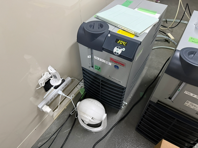
### Change the temperature of the fiber amplifier
According to the datasheet, the nominal temperature for the operation is 23 degrees. But the current temperature was. 21 degrees. This tempereture is close to the minimum value for the operation. So we increased the chiller setting from 19 degrees to 21 degrees. We waited for increaing the temperature. After the fiber amplifier temperature in the controller screen got 23 degrees, we tried the emisstion. the emission duration becomes longer, 1 mins 45 seconds but the power seems to be unstable (fig.8). We tried it again but the laser fall down soon (fig.9).
---
We gave up to recover the laser today. We turned off the whole laser system at last.
## Next
- switch the seed laser for NeoLASE
- try to recovery the 1st or 2nd fiber amp.


