[Uchiyama, Miyakawa, Tanaka, Ushiba]
Abstract:
We installed a new interlock system for the fiber laser amplifier.
We tested the function by turning on and off the master laser and it seems to work well.
Detail:
In this morning, we installed a new interlock system for the fiber laser amplifier.
First, we checked the water tubes inside the PSL to avoid te water accident and turned on the chiller: there is no water leakage.
Then, we checked if the situation doesn't change from yesterday by turning on master laser and fiber amplifier and confirmed that the laser output is about 1W and PMC can be locked without any problems.
So, we started to install the interlock system.
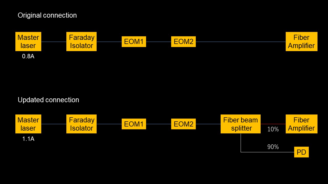
The fiber laser connection in this morning is as follows:
master laser -> Faraday isolator -> EOM1 -> EOM2 -> fiber amplifier.
So, we first measured the outpt power just before the fiber amplifier by changing the master laser current.
Following table shows the output power result.
| Master laser current [A] | Output power [mW] |
| 0.8 | 14 |
| 0.93 | 34 |
| 1.1 | 68 |
After that, we inserted fiber beam splitter (split ratio is 1:9) to split the beam into two.
To confirm if the beam separation is as we expected, we measured the output of each fiber and obtained the following results.
| Master laser current [A] | red (10% side) fiber output [mA] | white (90% side) fiber output [mW] |
| 0.8 | 1.2 | 12 |
So, the total loss of the fiber beam splitter is about 6%, which seems acceptable.
After confirming the fiber beam splitter works well, we increased the master laser current to 1.1A and connected the red fiber to fiber amplifier.
In that case, output power was measured as 4.5mW, which is within the operation range of the new fiber amplifier (between 1mW and 15mW).
In adition, we connected white fiber to PD (PDA100A2) for the new interlock system with absorption type ND filter of 1.0 OD.
The PD output voltage is about 2.4V with 10dB gain setting.
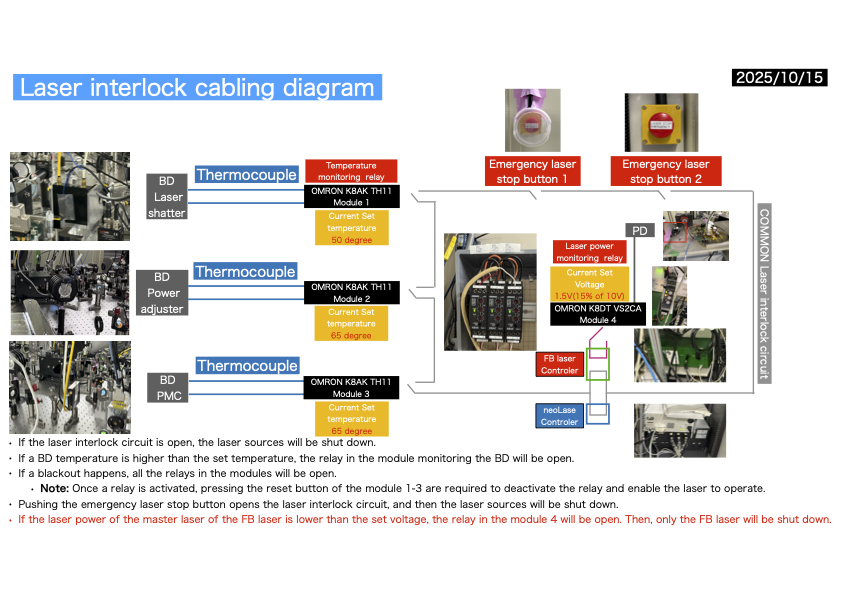
After that, we connected this PD to interlock circuit (connection of te interlock system will be reported later with Miyaawa-san or Uchiyama-san) and checked if the interlock circuit functions as we expected.
What we checked is:
1. Open/Close check with a multimeter by turing on/off the master laser.
2. Open/Close check with a fiber amplifier LEDs by turning on/off the master laser.
3. Turning off test of the fiber amplifier by turning on/off the master laser when fiber amplifier is ON and software output is OFF.
As a result, we confirmed that fiber amplifier is automatically turned off when the master laser becomes OFF and the fiber amplifier doesn't recover even if the master laser becomes ON after that unless we once turn off the fiber amplifier completely by keys.
This operation is as we expected, so the new interlock system seems to work well.
Note:
It would be better to check the fiber edges of optial fiber between EOM2 and fiber amplifier because the loss between them seems large (~23%).
Laser power displayed on the software is about 8-9mW while our measurement result is 4.5mW. We are not so sure the reason but it is not a serious issue at this moment because the output power is within operation range anyway, so we doesn't solve this inconsistency this time.


