Reports 1-1 of 1 Clear search Modify search
MIF (General)
kentaro.komori - 1:03 Saturday 04 October 2025 (35231) Print this report
Estimation of input-equivalent noise of SR560

[Miyoki, Tanaka, Komori]

Abstract:

We estimated the input-equivalent noise of the SR560 recently installed in the IMC slow loop.
The SR560 noise is lower than that of the CMS board below ~2 kHz, but higher above ~2 kHz.
We can conclude that the SR560 does not cause additional noise below ~2 kHz.

Detail:

The interferometer successfully reached the DC readout state, but its sensitivity is currently much worse than before the fiber laser failure (Fig. 1).
Please note that the feedforward gain has not yet been optimized and the calibration has not been updated.
On the other hand, since the heights of the violin peaks are similar, the sensitivity at high frequencies is likely not severely incorrect.

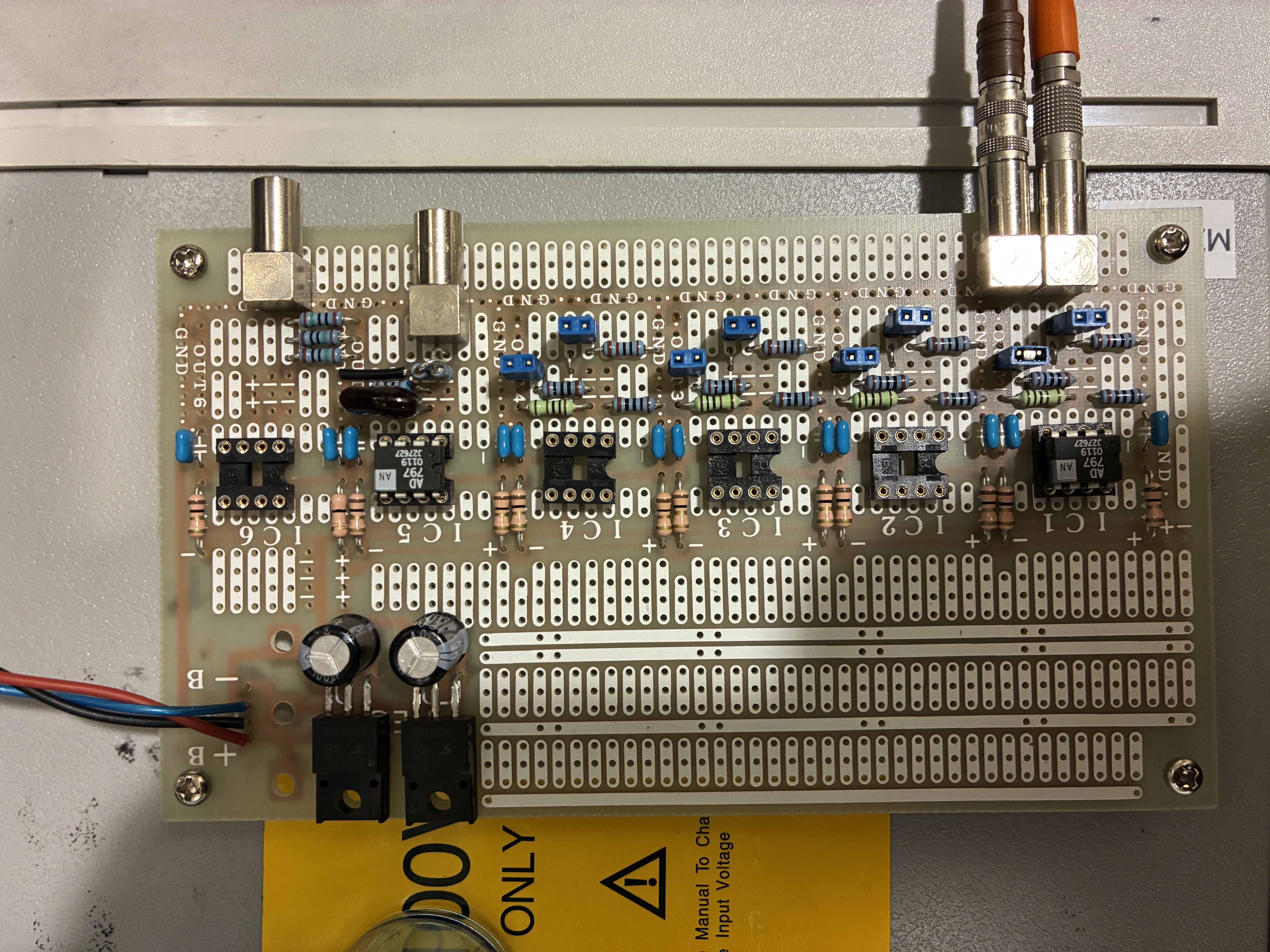
The SR560, which was recently installed between the notch filter and the IMC CMS board, was identified as a potential noise source responsible for the degraded sensitivity.
To evaluate this possibility, we compared the input-equivalent noise of the SR560 with that of the CMS board.

According to the datasheet, the input noise of the SR560 is 40 nV/√Hz at a gain of 2, which matches the current configuration.
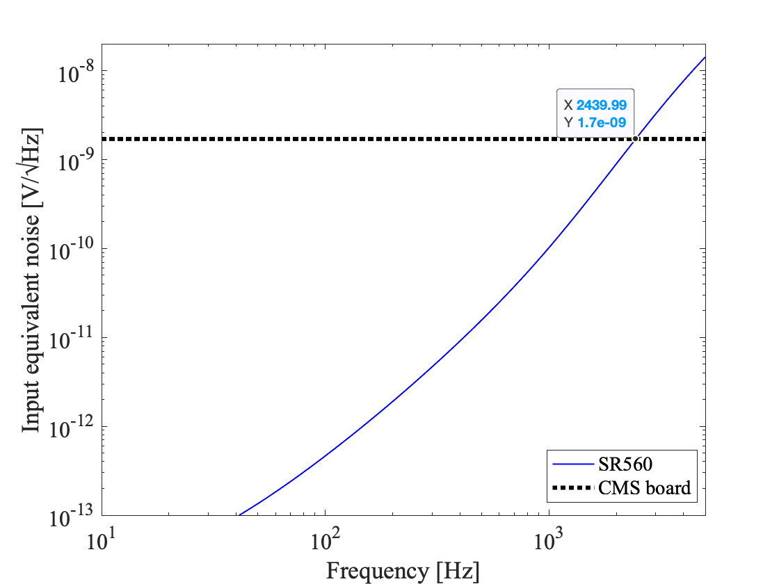
We conservatively estimated the SR560 noise contribution, converted into the input-equivalent noise for the IMC CMS as shown by the blue line in Fig. 2
This estimation is based on the transfer function of the boost filters, which are engaged during interferometer operation, and assumes CMS input gains of 0 dB.
For comparison, we also plot the conservative input-equivalent noise of the IMC CMS (black dotted line, 2 nV/√Hz), dominated by multiple AD829s at the input gain.

The SR560 noise is lower than the CMS noise below ~2 kHz, but becomes larger above ~2 kHz.
We can conclude that the SR560 does not cause additional noise below ~2 kHz.
On the other hand, it is possible that the larger noise floor from several hundreds of Hertz to 1 kHz originated from the CMS noise.

Proposal:

I would like to propose the following future commissioning tasks:

  • To check whether the noise above ~2 kHz originates from mere residual frequency noise, we should estimate the raw frequency noise by measuring the IMC length signal without the interferometer.

  • We should estimate the CARM optical gain. Since the CARM optical gain is proportional to the reflectivity of the RF sidebands, it may have been drastically reduced by the recent increase in optical loss due to frosting. If so, the CARM sensing noise contribution would be significantly larger than before.

  • We should search for the optimal beam spot and interferometer alignment to minimize frequency noise coupling into DARM.

Images attached to this report
Comments to this report:
tomotada.akutsu - 10:34 Saturday 04 October 2025 (35233) Print this report

(none)

shinji.miyoki - 23:18 Saturday 04 October 2025 (35234) Print this report

I made an amplifier that can drive up to +/-2.2V with a 50 ohm output and 50 ohm terminator by using AD797.  It utilized non-inverted configuration with 1.9 times gain. 

I confirmed that,

  • no circuit oscillation over MHz frequencies.
  • negligible phase delay at 100kHz.
  • to minimize the input voltage noise around ~1.5nV/rHz, I used ~100 ohm resistance, not 300 ohm, which was listed in the data sheet.
  • as a result of the parallel load resistance of 100 + 91 = 191 ohm and 50+50=100ohm, the output current of AD797 resulted in a 2.2V swing that was larger than 1.5V, that was generated from the circuit to the PZT of the master laser.

So we can replace SR560 to this low noise amplifier.

On the other hand, the inverted configuration using AD797 with a gain of 2 had ~100MHz level small circuit oscillation. I gave up on selecting the inverted configuration.

photo 1,2 and 3, 4 and 5,6 show 900kHz, 1MHz, and 100kHz input signals and output signals in the case of non-inverted configuration. Yellow is the input signal, and blue is the output signal. You can recognize,

  • Phase delay of 100kHz is so negligible,
  • Phase delay of 900kHz was 22.6ns/1100ns*360=7.4 degrees
  • wave distortion at 1 MHz is ugly.  The pahse delay was 61.6ns/1000ns*360=22 degrees.

Photo 7 shows the AD797 circuits. The right side is the non-inverted, the left side is the inverted configuration. Photo 8 shows the power supplier with +/- 20V outputs. Photo 9 shows ch1 and ch2  with 50-ohm terminator of the oscilloscope.

Photo 10 shows the output signal saturation at 2.24V due to the output current upper limit of the AD797. 


Images attached to this comment
Non-image files attached to this comment
shinji.miyoki - 15:29 Sunday 05 October 2025 (35236) Print this report

I made a monitor output by using the left side circuit of the non-inverted circuit in photo 7 in the original post. The circuit is the copy of the main circuit.

I confirmed to obtain 1.91*1.91 times output without any oscillation with 50 ohm output resistance for the output. The circuit oscillation appeared if no 50 ohm output resistance.
 

I checked the small signal response for 1MHz. The input voltage was 100mV0-p. As photo1, no wave form distortion, compared with the case of 2V0-p input in the original post.

The next, I will enclose this circuit in a metal box.

I updated the circuit information.

Images attached to this comment
Non-image files attached to this comment
shinji.miyoki - 8:59 Monday 06 October 2025 (35240) Print this report

In a box.

Images attached to this comment
shinji.miyoki - 15:02 Monday 06 October 2025 (35246) Print this report

[Tanaka, Miyoki]

We  tried this AD797 buffer. However, we found 22MHz oscillation with 70mV p-p amplitude in the monitor output if the output side was connected to the 150kHz Notch/50 ohrm terminator path to the PZT of the master laser for the neoLase laser.

We firstly suspected the IC instability even if I set a 10pF capacitor between the output and inverse input of AD797. So, I changed it 30pF. The other possibility is the too much feedback signals to the MHz frequency ranges excited some resonances. In such a case, we need a LPF for the MHz frequency rnge.

We retried the modified AD797, but same oscillation occured. In the next, we inserted a minicircuit DC-5MHz type LPF just before teh notch filter as photo.1. Then the oscillation has vanished. 

kenta.tanaka - 15:43 Monday 06 October 2025 (35249) Print this report

> We  tried this AD797 buffer. However, we found 22MHz oscillation with 70mV p-p amplitude in the monitor output if the output side was connected to the 150kHz Notch/50 ohrm terminator path to the PZT of the master laser for the neoLase laser.

Photo. 1 shows the 22 MHz oscillation.

> We retried the modified AD797, but same oscillation occured. In the next, we inserted a minicircuit DC-5MHz type LPF just before teh notch filter as photo.1. Then the oscillation has vanished.

(not photo.1) Photo. 2 shows the LPF.   

Images attached to this comment
kenta.tanaka - 18:52 Monday 06 October 2025 (35252) Print this report

After our PSL work, we measured the cross-over frequency between PZT ans EOM loops to check the effect of the new amplifer. Fig.1 shows the Cross-over frequency, dark curve is the TF before the gain compensation, and bright curve is after compensation. Before the gain compensation, the cross-over frequency is about 9 kHz. According to klog35090, the original cross-over frequency was 10 kHz. However, this frequency is determined so that the 150 kHz peak in the OLTF of the IMC loop across the 0dB line. Now, the 150 kHz peak is already reduced thanks to the preper notch filter implementation. Therefore, we attempted to restore the value of the cross-over frequnecy to the one when we used a fiber amlified laser, 14 kHz by adjusting the related gains, IMC-SERVO_{IN1, FAST}GAIN. The bright curver in fig.1 is after adjustment. the current cross-over frequency is 14 kHz.

And then, we measured the OLTF of IMC loop (fig.2). the current UGF is around 150 kHz this value is higher than the previous value, 134 kHz, according to klog35177

we compensated IMC-SERVO_IN2GAIN and LSC-MCL gain to keep the cross-over frequency. However, the cross-over frequency between PZT and MCE is several dB higher than before although it is compensated, according to Ushiba-san.  Then, Ushiba-san adjusted the cross-over frequency. Fig. 3 is the cross over frequency after the adjustment.

After that, we confirmed that IFO can reach PRFPMI_RF_LOCKED state. However, the lock duration seems to be shorter than before.

Images attached to this comment
shinji.miyoki - 21:54 Monday 06 October 2025 (35253) Print this report

Consequently, the present AD797 buffer amp seems to add noise in the laser frequency judging from the noise performance of PSL-PMC_MIXER_MON_OUT_DQ. It became always 2 time larger than the case of SR560.

So anyway, we removed this amp tonight. I will check its specrum later. 

Because the additional LPF with 2-pole 100kHz or 1-pole 30kHz seemed to be better to recover the pahse margin around the UGF of the IMC loop in the case of SR560 (Ushiba-kun will post later), I will make a passive LPF at 100kHz (33nF) or 30kHz (100nF) forming with 50 ohm output resistance of the AD797. 

takafumi.ushiba - 22:02 Monday 06 October 2025 (35255) Print this report

I measured OLTF of IMC loop (fig1) and cross over frequency between PZT path and EOM path (fig2) after setting SR560 as 2nd-order LPF at 100kHz.
Thin line in fig1 shows the OLTF when setting SR560 as the 1st-order LPF at 30kHz.

When LPF frequency becomes lower, the stracture above 100kHz becomes smoother.
This implies that the stracture above 100kHz comes from PZT path, so fine tuning of servo filter might improve the phase margin at high frequency and makes UGF slightly higher.

Anyway, the latest setting of IMC loop is OLTF UGF of 140kHz and crossover frequency of 15kHz.

Images attached to this comment
kenta.tanaka - 22:21 Monday 06 October 2025 (35256) Print this report

Ushiba, Tanaka

Since Ushiba-san pointed out that current IN2GAIN setting, 7dB is not optimized in terms of the offset, we measured and adjusted OFS_COMP for IMC CMS IN2GAIN from 3 dB to 7 dB so that MIXER_DAQ value is not changed in the current IN2GAIN setting. The procedure of tthe adjustement is followed in klog35203. fig. 1 shows the results in medm screen and Fig. 2 shows the timeseries of IMC-SERVO_MIXER_DAQ_OUT_DQ when IMC CMS IN2 switch turned on and off. The cursor in the top panel of fig.2 shows the DC level when the IN2GAIN is 3dB. Now, the DC level when IN2GAIN iss 7dB is the same as the one of 3dB. 

Images attached to this comment
shinji.miyoki - 9:26 Tuesday 07 October 2025 (35257) Print this report

If we have already suceeded to add 2-pole 100kHz LPF, the notch at 150kHz is still necessary?? If not necessary, we can remove 50ohm terminator and can be from the current limit problem to drive PZT. Or how about use 1-pole 30kHz LPF?

In basic in the PZT path, we should prepare several notch filters for the resonances of the PZT below 100kHz and kill other resonances above 100kHz by npoles-LPF. (This used to be utilized in CLIO). In addition, a LPF with a reletively low frequency should be installed just before the PZT to avoid noise injection from the analog circuit as a part components to form the total filter shape foe the PZT path. The direct drive from AD797(or HV amps) actually injected noises, as known in CLIO.

If we still need 1/10 in the commomode servo, It can be done by just a resistance devider just before the PZT input, and we can make an variable devider by using a varaible resistance in it.

Anolog filters and deviders are ideal to kill noises just before the PZT input.

Search Help
×

Warning

×