Miyakawa, Tanaka
We started investigating several unresolved issues from yesterday.
Initially, for some reason, we were unable to engage PRMI ASC in the PRFPMI configuration, unlike yesterday.
---
### Actuator Efficiency Check
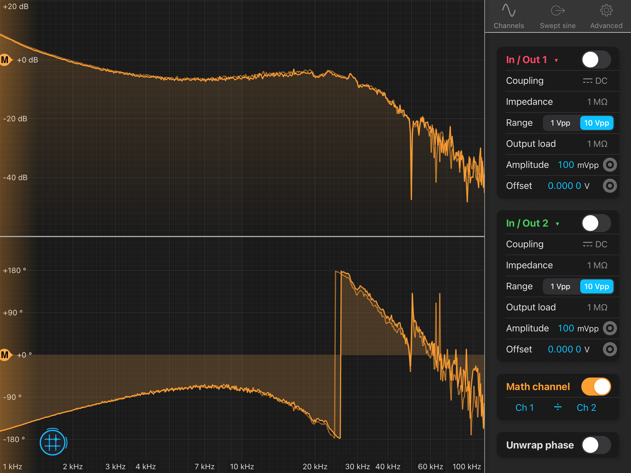
To understand the observed 8 dB increase in DARM loop gain, we checked whether the actuator efficiency had changed—possibly due to a temperature shift of ETMX.
We measured the transfer function (TF) from `ISCINF_L` to `ALS_DARM` when `ALS_CARM` was locked (i.e., during the `ENGAGE_FNC_PNC_XY` state of the `LSC_LOCK` guardian).
Figure 1 shows the results: the red line is today's TF, and the brown line is the previous measurement.
No significant change was observed, indicating that the gain increase in DARM is not due to actuator efficiency changes caused by ETMX temperature variations.
---
### Relocating the 150 kHz Notch Filter in the IMC Loop
The CARM TF shows a large resonance peak around 150 kHz.
This resonance appears to approach the 0 dB line when the CARM UGF is increased to 50 kHz by raising the gain by +10 dB.
Since this resonance originates from the IMC loop, we had previously installed a 150 kHz notch filter in the EOM path. However, it does not appear to be effective.
We therefore attempted to move the notch filter to different locations:
- **From EOM path → PZT path**:
Figure 2 shows the IMC OLTFs. The bright line represents the TF with the notch in the PZT path, and the dark line represents the TF with the notch in the EOM path.
The peak at 150 kHz was slightly reduced (by <1 dB).
- **From PZT path → INPUT1 of CMS**:
Figure 3 shows the results. The bright line corresponds to the notch before the CMS INPUT port; the dark line corresponds to the notch in the EOM path.
Although the overall gain increased, the peak height also increased, indicating the notch had no significant effect at this location.
Based on these results, we decided to install the notch filter in the **PZT path** for now.
---
### Cross-over Frequency Adjustment (PZT ↔ EOM)
We then adjusted the cross-over frequency between the PZT and EOM loops.
Previously, it was set to 14 kHz using `IN1GAIN = 19 dB` and `FASTGAIN = 27 dB` (see klog35055).
This time, we reduced it to 10 kHz by setting `IN1GAIN = 16 dB` and `FASTGAIN = 30 dB`.
However, the 150 kHz resonance peak was not significantly reduced (Fig. 4).
We also measured the CARM TF under this condition (10 kHz cross-over).
Figure 5 shows the CARM TF; the relative gain between 50 kHz and the 150 kHz resonance is ~6 dB.
This suggests that even with +10 dB gain, the resonance peak should remain below 0 dB.
However, the change in resonance peak height does not match the IMC-only measurement. The reason is unclear, but the current state appears acceptable.
After these trials, we realized we had **forgotten to adjust the CARM gain** after modifying the IMC gain.
When we replaced the laser, we increased `IMC IN1GAIN` from 14 dB to 19 dB, and should have increased the CARM gain by +5 dB to maintain the original UGF.
Therefore, **5 dB of the 11 dB discrepancy** in CARM UGF can be explained by this oversight.
The remaining **6 dB discrepancy** remains unexplained.
---
### Demodulation Phase Check
We attempted to verify whether the RF demodulation phases used in each LSC DOF are optimized.
Although we couldn’t find the previous reference measurements, we checked the current situation.
#### PRCL and MICH
We excited {PRM, BS} in the L-direction at {84.125 Hz, 90.125 Hz} while PRMI was locked with 3f signals, and observed the spectra of POP45 and POP17 I/Q signals, which serve as the error signals:
- **Fig. 6**: POP45 — the 84 Hz peak is larger in **I** than **Q** → PRM excitation
- **Fig. 7**: POP17 — the 90 Hz peak is larger in **Q** than **I** → BS excitation
While this confirms the expected coupling, both demodulation phases are not optimal.
However, since the PRCL and MICH TFs remain unchanged, we decided **not to modify their demodulation phases** for now.
#### CARM
We excited the laser frequency at 90.125 Hz using `K1:LSC-CARM_SERVO_EXC_A_CALI_EXC` while PRFPMI was locked without ASC.
We measured the spectra of REFL45 I/Q signals from both **REFL PDA1** and **REFL PDA3**:
- **Fig. 8**:
- REFL PDA1: The 90 Hz peak is larger in **I** than **Q**, but the I-signal does not double even under optimal phase conditions.
→ The demodulation phase is not optimal, but cannot fully explain the 6 dB discrepancy.
- REFL PDA3: 90 Hz peaks in I and Q are almost the same.
→ Also not optimal.
---
### Conclusion
- 5 dB of the CARM UGF discrepancy is due to missing gain compensation.
- The remaining 6 dB is not explained by actuator efficiency, IMC notch filtering, or demodulation phase.
- Further investigation is needed to fully restore optimal PRFPMI locking.


.png)


.png)