Uchiyama, Tanaka
## Abstract
We measured the PMC open-loop transfer function (OLTF) and adjusted the unity gain frequency (UGF) to 4 kHz.
We also inserted a 150 kHz notch filter just after the FAST OUT port in the EOM path of the IMC loop, and adjusted the IMC OLTF UGF to 92 kHz and the cross-over frequency between the PZT and EOM loops to 14 kHz.
---
## What We Did
### 1. PMC OLTF Measurement
We measured the PMC OLTF using Moku:Lab. Figure 1 shows the result: the UGF was about 2.3 kHz. The overall gain appeared to be approximately 6 dB lower than in klog35007, where the UGF was 4 kHz, despite using the same RF oscillator and Common Gain value. Although the reason is unclear, we increased the gain so that the UGF returned to ~4 kHz (Fig. 2). I have already modified the PMC Guardian script to reflect the gain settings in the DOWN state.
---
### 2. Inserting a 150 kHz Notch Filter in the IMC EOM Path and Adjusting the IMC OLTF
We inserted a 150 kHz notch filter designed by Shimode-san, with an adjustable notch depth depending on the resistance used (see details in the AEL blog).
#### a. Before inserting the filter
We first measured the IMC OLTF before inserting the notch. Figure 3 shows the result. The UGF was about 76.3 kHz, which is lower than the previous value of 95 kHz reported in klog34871. A peak appeared at 148 kHz with a height of ~ –3.2 dB. If the curve at 76 kHz is extrapolated smoothly to 148 kHz, the expected value would be around –5.2 dB, indicating that the actual peak was ~2 dB higher than the trend. According to Shimode-san, using one resistor yields a notch depth of ~–3 dB, which was consistent with our confirmation (Fig. 4).
Thus, we chose to use the notch filter with one resistor.
#### b. Cross-over frequency measurement
We also measured the cross-over frequency between the PZT and EOM loops. Figure 5 shows the result: the cross-over was ~10 kHz, consistent with klog34871.
#### c. After inserting the filter
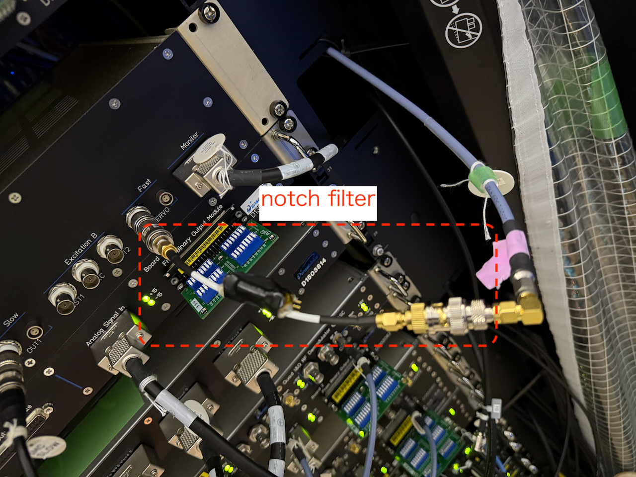
We inserted the notch filter just after the FAST OUT port on the IMC servo (Fig. 6). Then, we measured the IMC OLTF again. Figure 7 shows the result — the bright yellow curve corresponds to the configuration with the notch filter, and the dark yellow curve is without it.
At 148 kHz, the peak height was reduced by only ~0.5 dB, which is smaller than expected. The discrepancy between the expected filter performance (~–3 dB) and the observed effect may be due to an impedance mismatch between the filter and the FAST OUT port. The filter impedance is 50 Ω, but the output impedance of FAST OUT is unknown. According to Miyakawa-san, both the EOM amplifier and the EOM itself have 50 Ω impedance. Therefore, to maximize filter performance, it should be placed between the amplifier and the EOM.
#### d. Final tuning
We adjusted the UGF and cross-over frequency by changing the `FASTGAIN`, `IN1GAIN`, and the number of resistors in the notch filter. In the final configuration, we set:
- `IN1GAIN` = 18 dB
- `FASTGAIN` = 27 dB
- Notch filter: **no resistor**
This yielded:
- UGF ≈ 92 kHz (Fig. 8)
- Cross-over frequency ≈ 14 kHz (Fig. 9)
I have updated the IMC Guardian script to reflect these gain values in both the `DOWN` and `LOCK_PREP` states.


