Ushiba, Tanaka, Komori (remote)
## Abstract
23.585 kHz mode seems to be usefull for the beacon ASC compared with other modes. However, the P/Y coupling in QPD got worse than May 31th.
## What we did
First, we tried to check which signal generated by the 4 modes, which were found previously, can be used for the alignment control. On the other hand, we could not observed any peaks in QPD signals even though we injected the beacon signal. Then, we found that the DAC output for beacon EXC was not connected to the new 3-30 Hz HPCD after swapping work in klog34246. So we entered the mine and connected the DAC output for beacon EXC to the new 3-30 Hz HPCD. After that, we confirmed that the beacon signals could be seen in QPD signals.
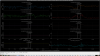
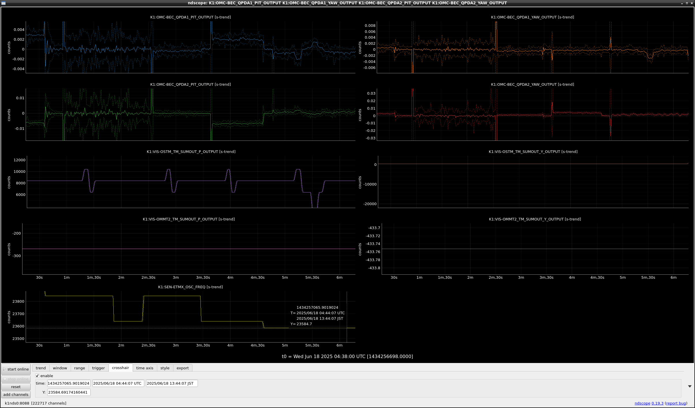
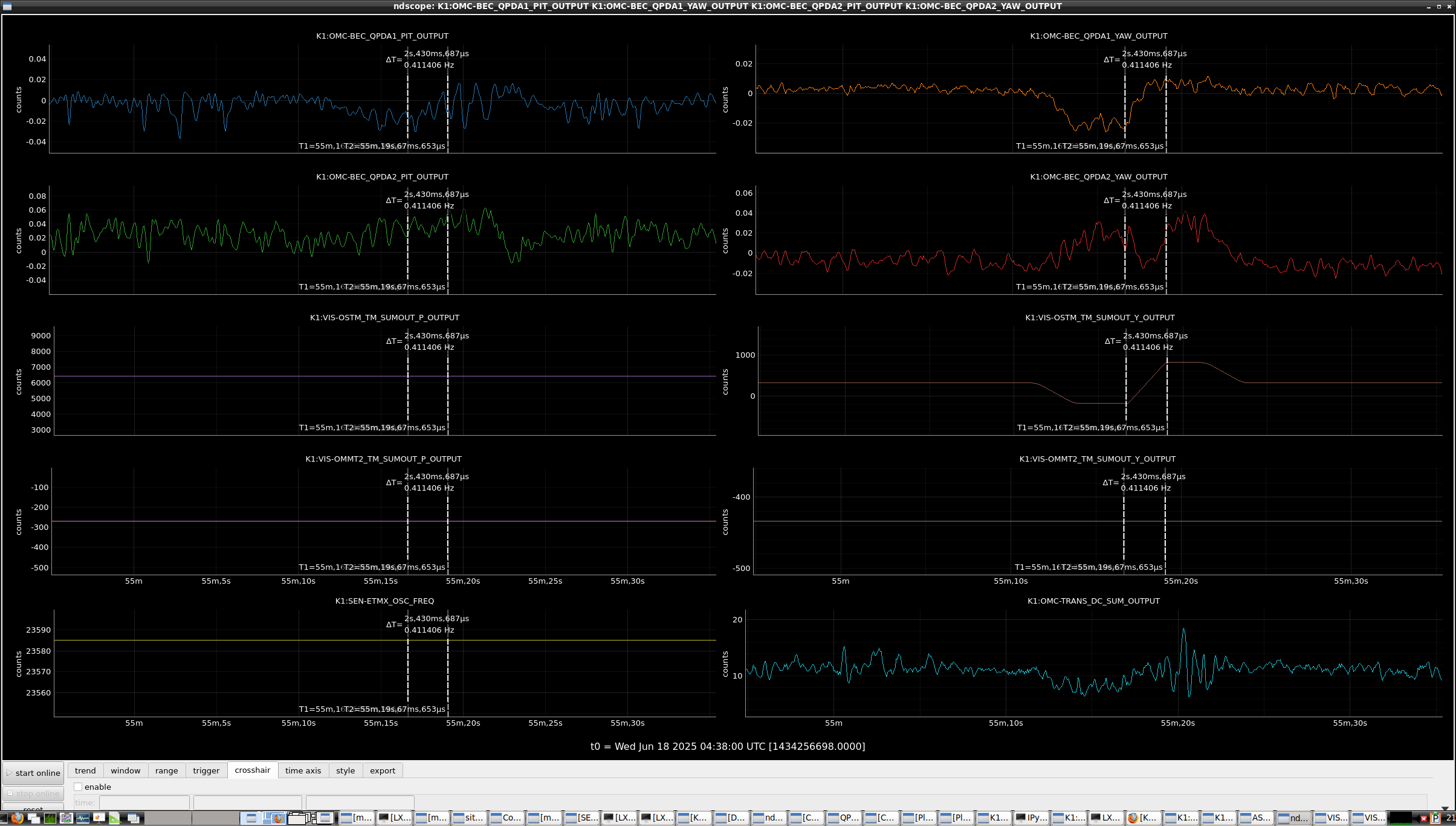
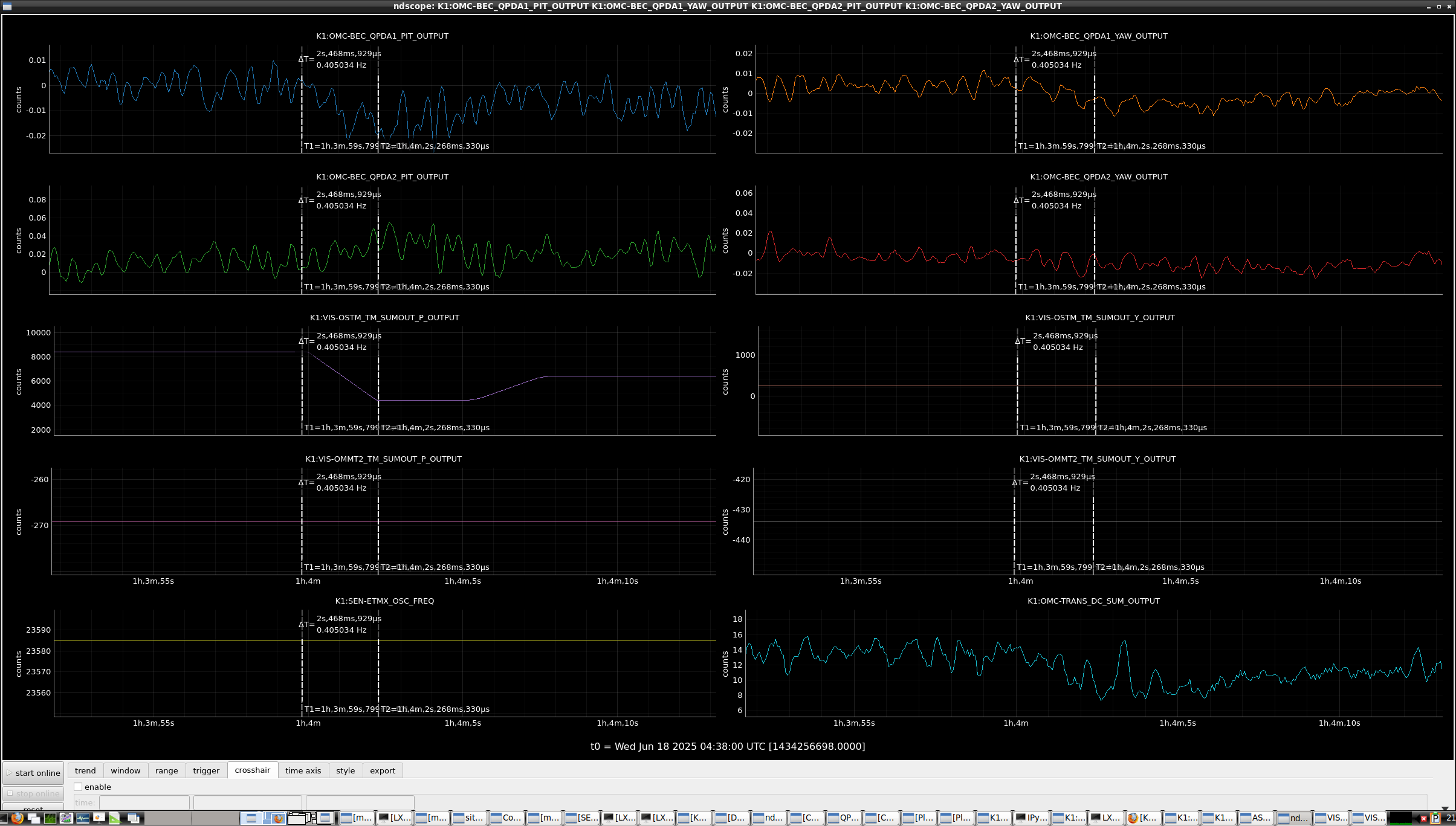
Then, we continued the check. We excited ETMX at 23.940 kHz, 23.843 kHz, 23.638 kHz, and 23.585 kHz, one by one and checked whether the QPD signals moves or not by moving OSTM PIT with DC, one by one. Fig. 1 shows the time series of QPD signals, OSTM and OMMT2 SUMOUT, and beacon excitation frequency. As you can see, when beacon excitation frequency was 23.585 kHz, QPD signal responded as OSTM PIT moved. Therefore, 23.585 kHz seems to be usefull for the beacon mode.
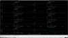
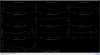
Second, we checked whether the signals become postive and negative when the DC alignment changes. Fig. 2 and Fig. 3 show the result when OSTM was moved in PIT and YAW direction, respectively. The QPD1 signal seems to cross 0 when OSTM moved. So we tried to use the QPD1 signal for OSTM control.
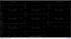
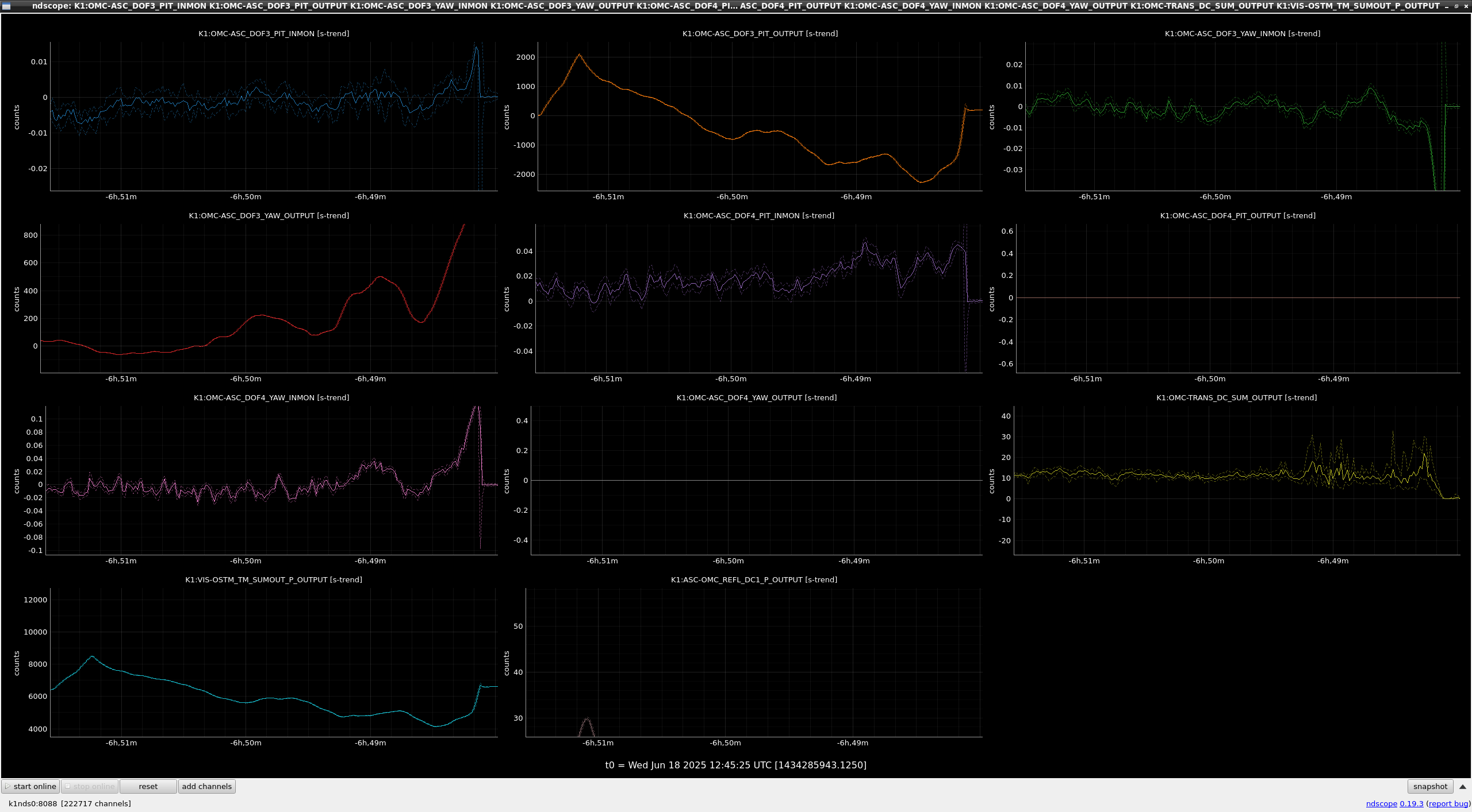
After that, we tried to engage both OSTM PIT and YAW controls with QPD1 signals. However, the feedback signals started to drift (fig.4) and OMC lock went down at last.
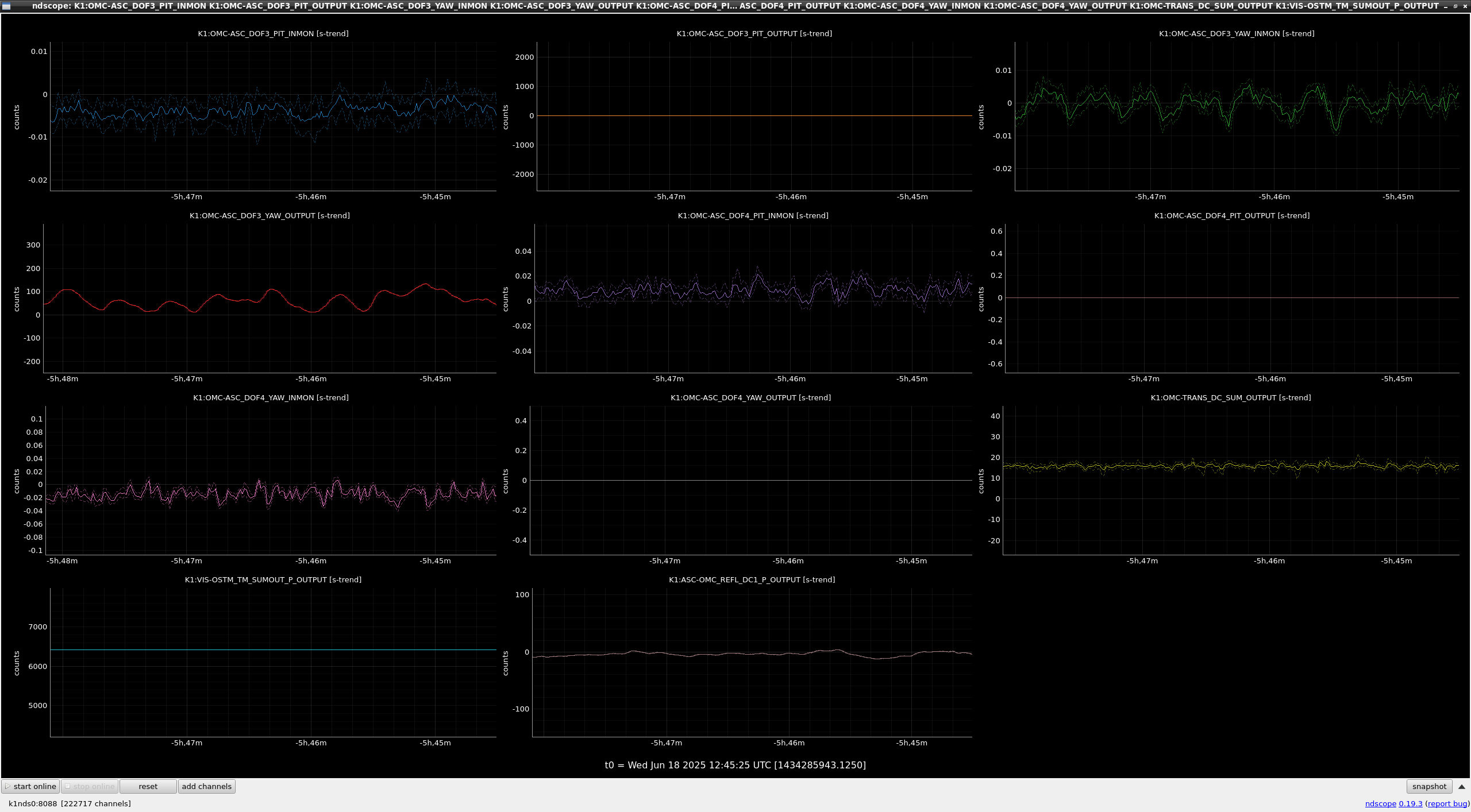
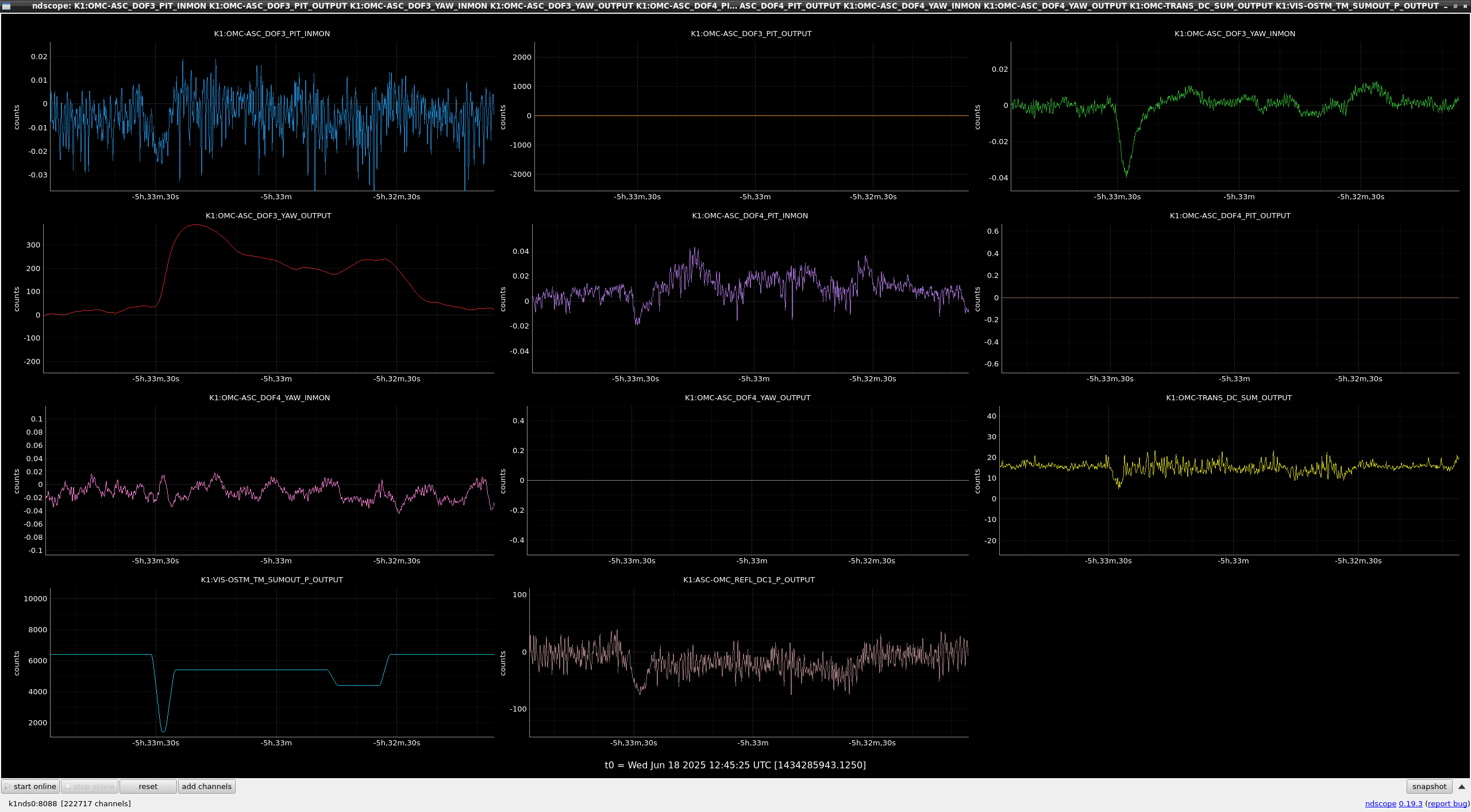
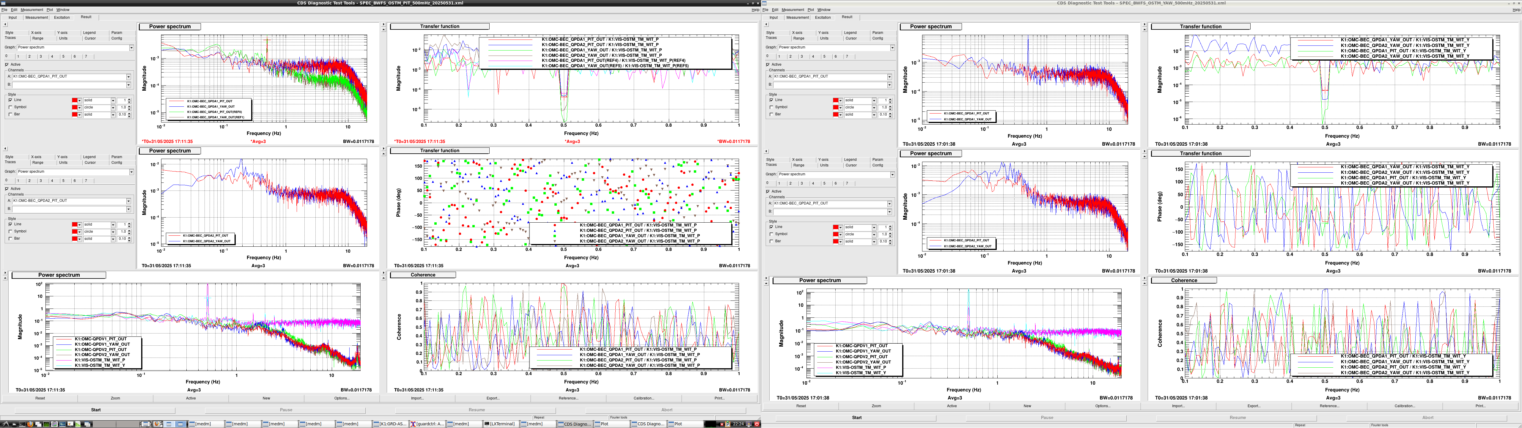
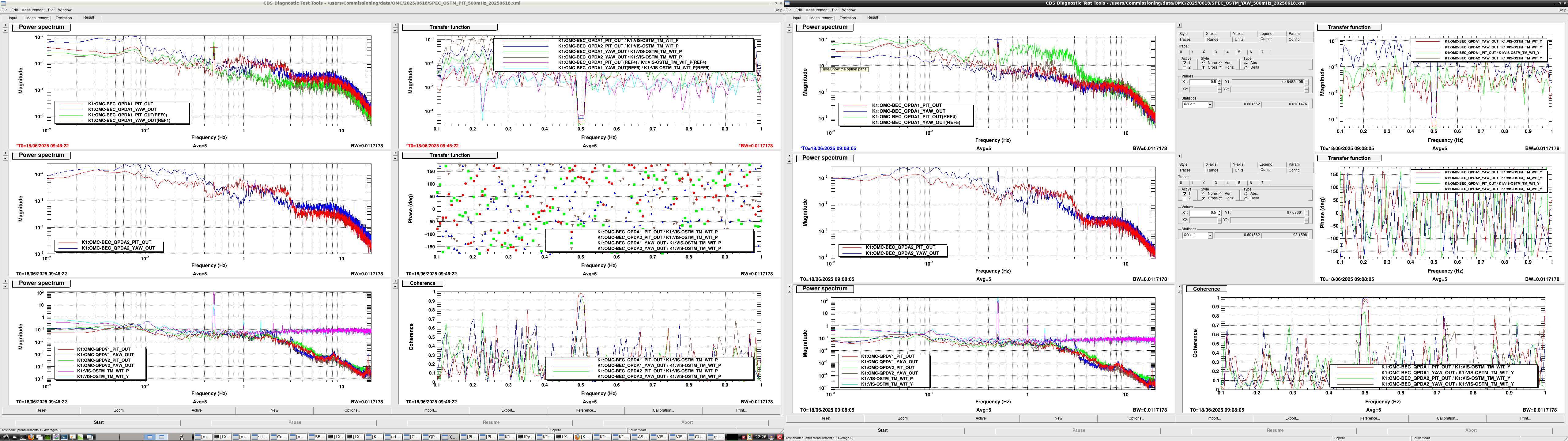
Then we tried to engage only the OSTM YAW control. The control seems to be stable when the YAW control was engaged (fig.5). In this state, we moved OSTM PIT with DC, and we found that the OSTM PIT error signal seemed to be not moved but the YAW feedback signal moved. This indicated that the PIT/YAW coupling in QPD1 signal seems to be large (fig.6). On the other hand, on May 31th, the P/Y coupling in QPD1 seems to be decoupled (fig.7). We turned off the control, excited OSTM YAW at 500 mHz and measured the P/Y coupling. Fig.8 shows the result. the coupling become large for some reason, unfortunately.
Anyway it is necessary to decouple the P/Y coupling in QPD1 to engage both PIT and YAW control at the same time.
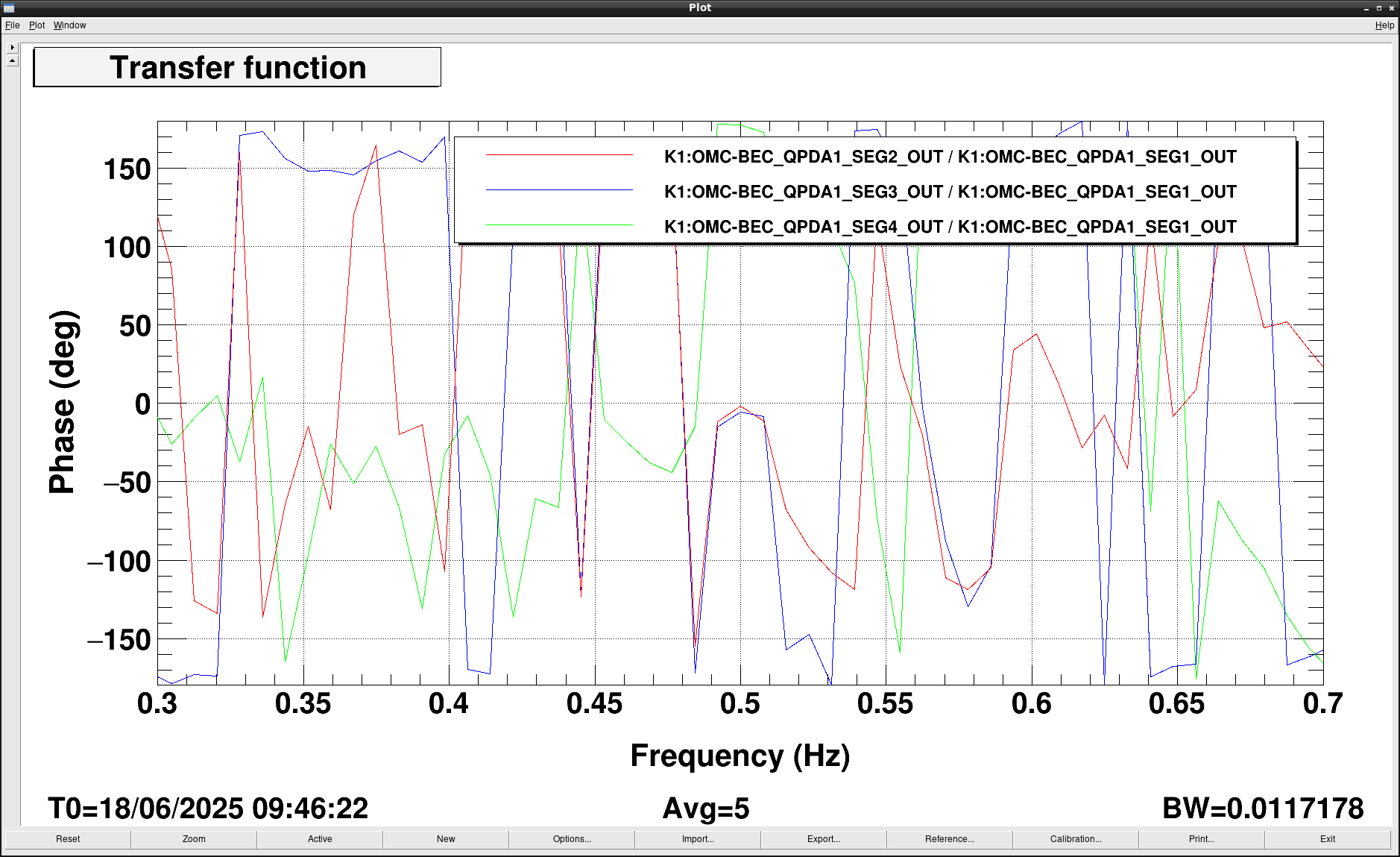
Also, we found that the phase between the segment 1 and segment 3 was strange when the OSTM PIT/YAW excitation. According to the layout of the segments, Segment 3 is in the diagonal side about Segment 1. So the phase of the segment3 signals should be opposite about the phase of the segment 1 signal. However, actual phase situation seems to differ from the expectation. Fig.9 shows the relative phase between segment1 and the others. The phase between segment 1 and 3 seems to be in phase. This indicates the demod. phase of 24 kHz changes compared with the one on May 31th...


