Summary
I identified and corrected issues in the coordinate handling of TCam-based Pcal beam position estimation for both Pcal-X and Pcal-Y. The previous implementation had sign and axis direction errors due to a misunderstanding of the image coordinate system and TCam orientation. As a result, the estimated beam positions used in the RT model were inconsistent with the actual beam positions on the test mass. This affects the final displacement calibration of the interferometer. The corrections lead to changes of approximately −0.86% (Pcal-X) and +0.97% (Pcal-Y).
Update of Pcal beam position parameters for RT model
I reviewed and corrected the handling of beam position estimation from TCam images for both Pcal-X and Pcal-Y. The main issues and corresponding corrections are summarized below.
Issues in the previous implementation
- The y-axis direction was not converted from the image coordinate system (where +y is downward) to the physical TM coordinate system (where +y is upward).
- For Pcal-X, the x-axis was not inverted to match the physical coordinate system, despite the TCam image being flipped horizontally.
- The difference between estimated and designed beam positions was calculated in the wrong order, which led to incorrect sign conventions.
Corrections applied
- All [x, y] beam positions were converted to the physical TM coordinate system by flipping the y-axis.
- For Pcal-X, the x-axis was inverted to account for the flipped image orientation.
- The difference between the estimated and designed positions is now computed as (estimated − designed).
- New parameters
Estimated_path1_HR_cordandEstimated_path2_HR_cordwere introduced. These represent the estimated beam positions in a TM-centered coordinate system with x to the right and y upward, including all necessary image and coordinate corrections.
Beam position parameter values
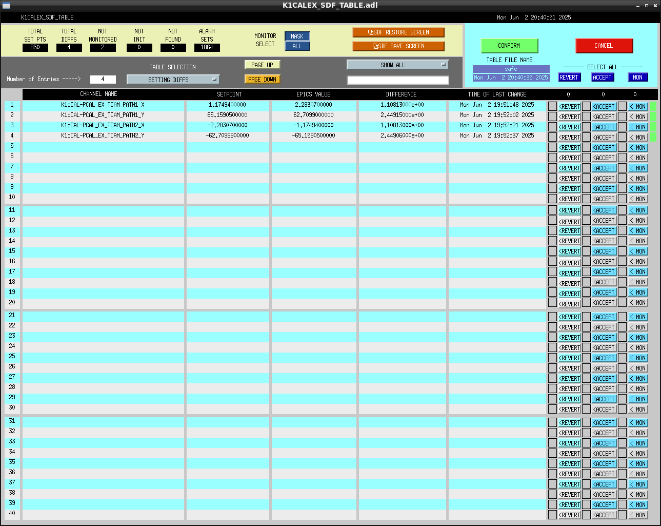
Pcal-X (unit: mm)
| Path | Before | After (Estimated_path*_HR_cord) |
|---|---|---|
| Path1 | +1.175, +65.159 | +2.283, +62.710 |
| Path2 | −2.283, −62.710 | −1.175, −65.159 |
Pcal-Y (unit: mm)
| Path | Before | After (Estimated_path*_HR_cord) |
|---|---|---|
| Path1 | −0.234, +69.902 | −0.05071, +61.36208 |
| Path2 | −0.051, −61.362 | −0.23378, −69.90192 |
Note: These values are not yet updated in the RT model. I plan to apply the updates later today.
Impact on IFO calibration
The correction factor related to beam mis-centering is calculated as:
1 + (a · b) × (M / I)
Where:
- a: vector sum of Path1 and Path2 beam positions (relative to TM center)
- b: vector from the TM center to the main IR beam position
- M/I: mass/inertia constant for the test mass
Pcal-X:
- Before correction:
1 + (a·b)·(M/I) = 1.00431 - After correction:
1 + (a·b)·(M/I) = 0.99569 - Change: approximately −0.86%
Pcal-Y:
- Before correction:
1 + (a·b)·(M/I) = 0.99488 - After correction:
1 + (a·b)·(M/I) = 1.00456 - Change: approximately +0.97%

