Reports 1-1 of 1 Clear search Modify search
CAL (General)
Shingo Hido - 18:51 Friday 30 May 2025 (33976) Print this report
3-30 Hz HPCD transfer function measurements

with Dan, YamaT, SawadaT, Sembo

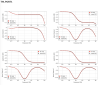
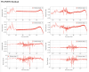
As noted in klog#33920, the HPCD described in klog#33854 was successfully installed. However, the transfer function measurements was unsuccessful. Investigation into the root cause was conducted, but no definitive reason could be identified.

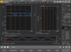
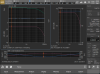
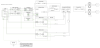
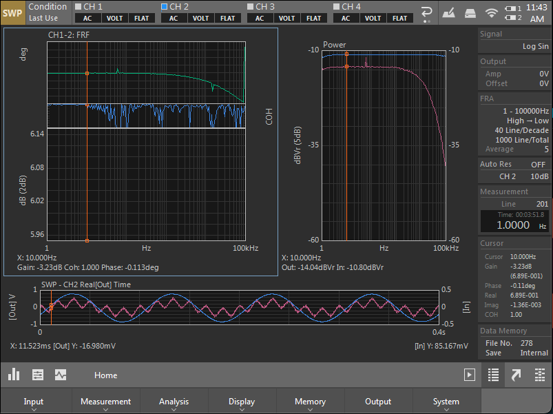
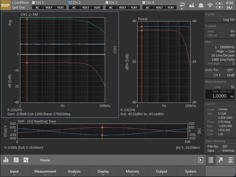
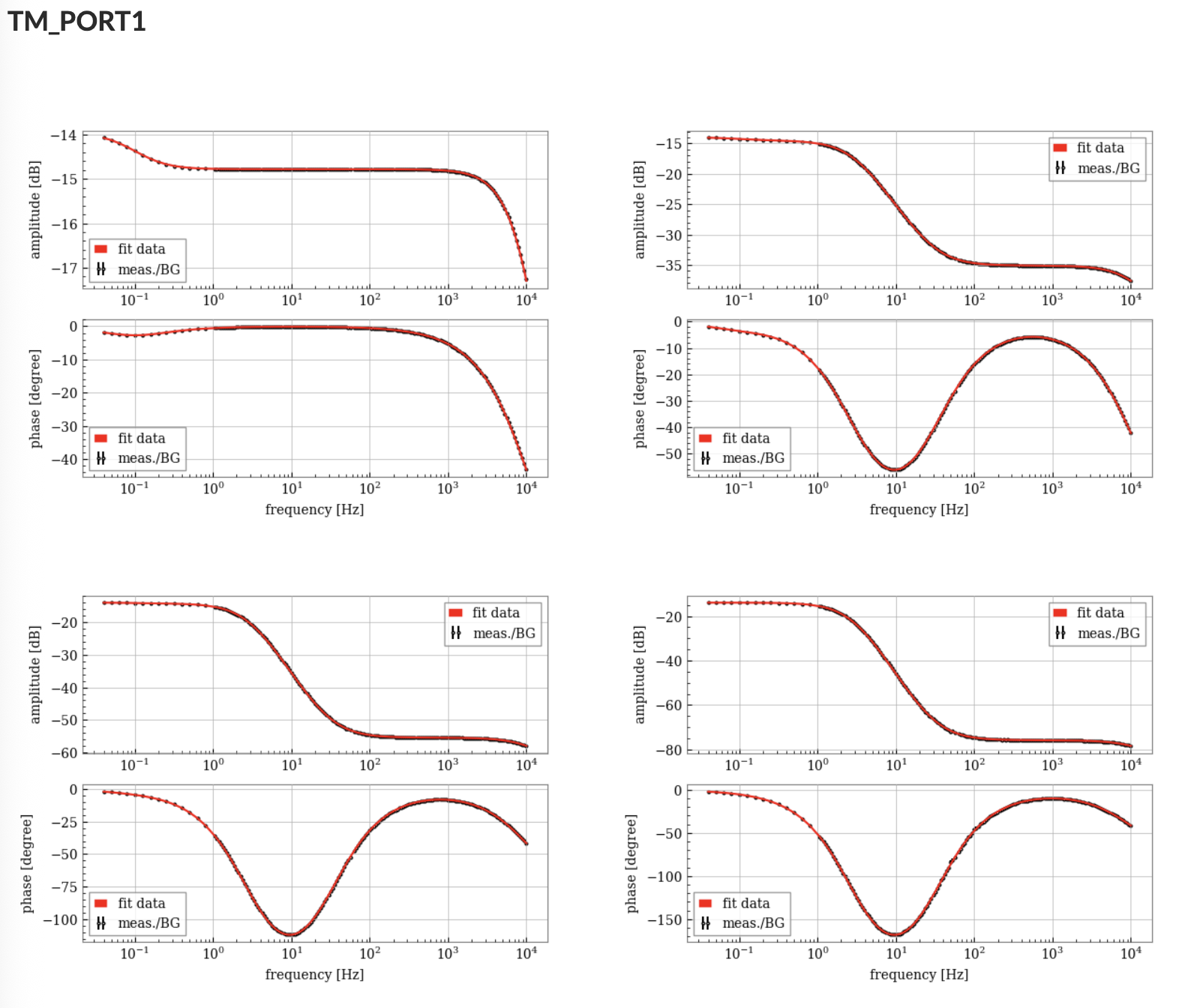
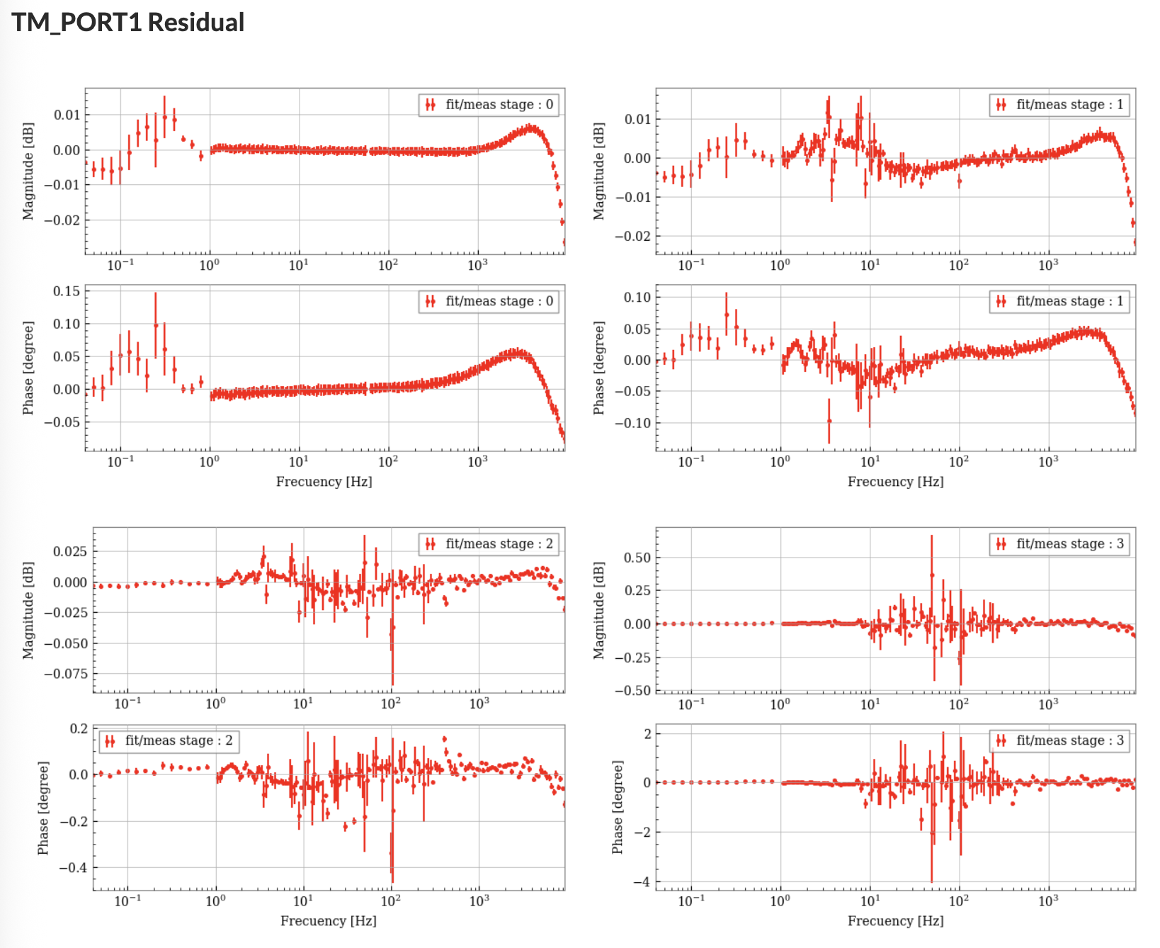
After confirming that no abnormal voltage signals were present in the circuit or measurement setup, we replaced the SR560 which had been showing unusual behavior. A measurement equivalent to that shown in Fig.1 was then performed (Note that the coherence shown is in the range 0.999 – 1.0). As illustrated in Fig.2, the output signal (red trace in the lower panel) was clearly improved. This suggests that the issue was likely not due to the circuit itself.

Note:

Measurement equipment such as the SR560, spectrum analyzer, and related instruments used in this measurements were brought back to the analysis building.
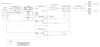
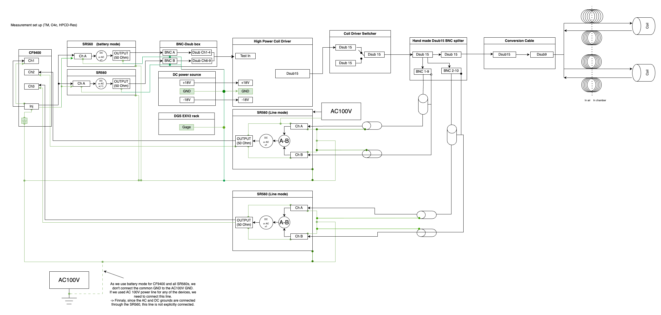
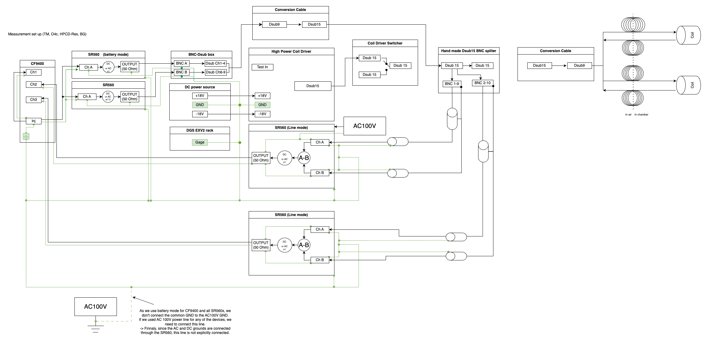
Please refer to klog#33823 for the measurement setup and another example of HPCD transfer function measurements.

Images attached to this report
Comments to this report:
dan.chen - 6:18 Saturday 31 May 2025 (33982) Print this report

Inductance and Resistance Measurement of ETMX TM Coils

During the preparation for the TF measruement trial, we measured the resistance and inductance of the test mass (TM) coils of ETMX. The resistance was measured using a Sanwa CD772 multimeter, and the inductance was measured using a Sanwa LCR700 meter.

  • The temperature of the IM at ETMX was approximately 40 K.
  • Measurements were taken at the D-sub15 connector. This connector is originally connected to the switcher, but during our CAL measurements, it is connected to a separator we made.
  • The inductance measurement at 100 Hz showed large fluctuations, with variations up to several tens of μH.
  • Measurements at other frequencies were relatively stable. At 1 kHz, the variation was on the order of a few μH.
Coil Pin at D-sub15 connector Measured R [Ohm] (±0.1 Ohm) Measured L [μH] (100 Hz) Measured L [μH] (1 kHz) Measured L [μH] (10 kHz) Measured L [μH] (100 kHz)
H1? 1–9 59.2, 59.2 302, Q=0.003 319.3, Q=0.033 314.6, Q=0.331 403.9, Q=2.63
H2? 2–10 59.2, 59.1 338, Q=0.003 320.6, Q=0.033 314.0, Q=0.330 408.2, Q=2.58
H3? 3–11 59.5, 59.7 302, Q=0.003 318.1, Q=0.033 314.7, Q=0.324 405.0, Q=2.62
H4? 4–12 60.5, 60.7 320, Q=0.003 317.2, Q=0.032 313.0, Q=0.320 406.6, Q=2.55
Images attached to this comment
takahiro.yamamoto - 18:55 Monday 09 June 2025 (34122) Print this report
[Hido, SawadaT, YamaT]

Though we re-tried the transfer function measurement of z30:p3 coil driver, we couldn't complete it again.

-----
Because required jumper pin was not inserted to z30:p3 coil driver, we needed to insert it before starting the TF measurement. It's difficult to insert it without removing chassis. So we uninstalled z30:p3 coil driver from EXV2 rack once and then returned back to EXV2 rack after installing a jumper pin. It took long time and we didn't have enough time for measuring TFs. So we gave up to complete this task today. Now EXV2 rack is in the situation that we can start TF measurement. It's only a progress today.

By the way, we didn't know the fact that jumper pin was required, and also the fact that jumper pin was inserted to another z10:p1 coil driver at EXV2. If this kind of information was shared in the morning briefing, we could focus only on jumper pin work today's morning and we can assign another task on afternoon because half day is not enough for the TF measurements. Now commissioning time is very limited. So it's so wasted time to miss half day because of the shortage of information sharing...
takahiro.yamamoto - 10:50 Tuesday 10 June 2025 (34134) Print this report
This is the timeline of yesterday's work.

1023 mine in
1027 X-arm in
1040 arrived at EX
1042 EXV in
1044 requested ETMX safe
1045 started measurement setup
1110 noticed jumper pin issue
1128 completed measurement setup
1221 EXV out
1233 X-arm out
1336 mine out

1419 mine in
1424 X-arm in
1438 EXV in
1448 unplugged cables from HPCD
1453 inserted jumper pin
1456 re-installed HPCD
1458 plugged cables to HPCD
1520 recovered HPCD
1529 measured rough TF as quick recovery check
1612 deconstructed measurement setup
1629 EXV out
1650 X-end out
1706 X-arm out
1710 mine out

dan.chen - 16:12 Tuesday 10 June 2025 (34140) Print this report

Title:
Successful Measurement of New HPCD (3–30 Hz) Transfer Function
Members:
[YamamotoT, HidoS, ChenD]

We finally succeeded in measuring the transfer function of the new HPCD unit.

Although a detailed analysis is still ongoing, no obvious anomalies were observed in the data during on-site review. The system behaved as expected throughout the measurement.

After the measurement, all equipment—including the SR560, CF9400, and related cables—was cleaned up and brought back to the Mozumi analysis building.

At present, the coil driver switcher is configured such that it can toggle between the standard HPCD and the newly added 3–30 Hz HPCD with a series resistor. This setup allows us to switch between the two configurations as needed.

A more detailed report will follow after further analysis.

takahiro.yamamoto - 16:25 Tuesday 10 June 2025 (34142) Print this report
Timeline of this work is as follows.
0929 mine in
0933 X-arm in
0946 EXV in
0948 IFO DOWN and ETMX safe
1000 setup of measurement equipment
1042 start measurement
1416 finish measurement
1418 cleanup measurement setup
1441 ETMX ALIGNED
1458 EXV out
1500 X-end out
1514 X-arm out
1521 mine out
dan.chen - 17:31 Tuesday 10 June 2025 (34143) Print this report

Grounding Configuration during the Measurement

During the successful transfer function measurement of the new HPCD (3–30 Hz), we carefully constructed a grounding (GND) scheme to ensure measurement reliability. The key points are as follows:

  • One of the SR560 units had a faulty battery, making it necessary to operate it using AC power.
  • To connect the DC GND and AC GND, we used a 3-prong AC power cable with this SR560. As a result:
    • The AC GND was internally connected to the BNC input/output shells of the SR560.
  • The DC GND and the measurement system GND were intentionally connected to a common GND point.
  • The SR560 chassises were also connected to this shared GND to unify all ground references.

We believe that this careful configuration enabled safe and correct measurement of the transfer function.

Diagrams

  • Fig. 1: Wiring diagram for the main transfer function measurement
  • Fig. 2: Wiring diagram for the background TF measurement setup
Images attached to this comment
dan.chen - 17:38 Tuesday 10 June 2025 (34144) Print this report
Shingo Hido - 14:50 Sunday 15 June 2025 (34229) Print this report

I performed a fitting onthe measured data. Fig.1 and Fig.2 shows the results and residuals between measured data and fitted curve.
The complete results have been upload to the wiki. Thre is no significant deviation in 0.04 Hz to 10 kHz range.
Attached is a text file summarizing the input values for 'ETMX_TM_COILOUTF_H{1, 2, 3, 4}'.

Images attached to this comment
Non-image files attached to this comment
Shingo Hido - 12:55 Monday 16 June 2025 (34244) Print this report

 I updated the some parameters in ETMX_TM_COILOUTF_H{1, 2, 3, 4}.

Search Help
×

Warning

×