With: Shingo Hido, Hiroshi Takaba, Takahumi Ushiba, Masakazu Aoumi
Summary
We conducted a transfer function and noise measurement of the High Power Coil Driver (HPCD) unit that is planned to be newly installed at ETMX. While most channels behaved as expected, Channel 3 showed an unexpected transfer function response. We concluded that this unit requires repair before installation.
Background
- The current coil driver for the test mass (TM) of ETMX is a High Power Coil Driver (HPCD) with a beacon input port.
- To reduce actuation noise during observation, we plan to use an HPCD with an additional output resistor and the beacon input port, if possible.
- The configuration measured on May 19 was the currently installed HPCD + beacon input.
- Today, we tested another HPCD unit (with beacon input) that will be modified by adding an output resistor and made switchable.
- This measurement was a pre-installation test of that unit.
Measurement Target
- HPCD with beacon input port (S/N: S2315284)
- Design document: S2315284 Design Doc
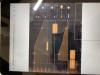
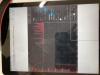
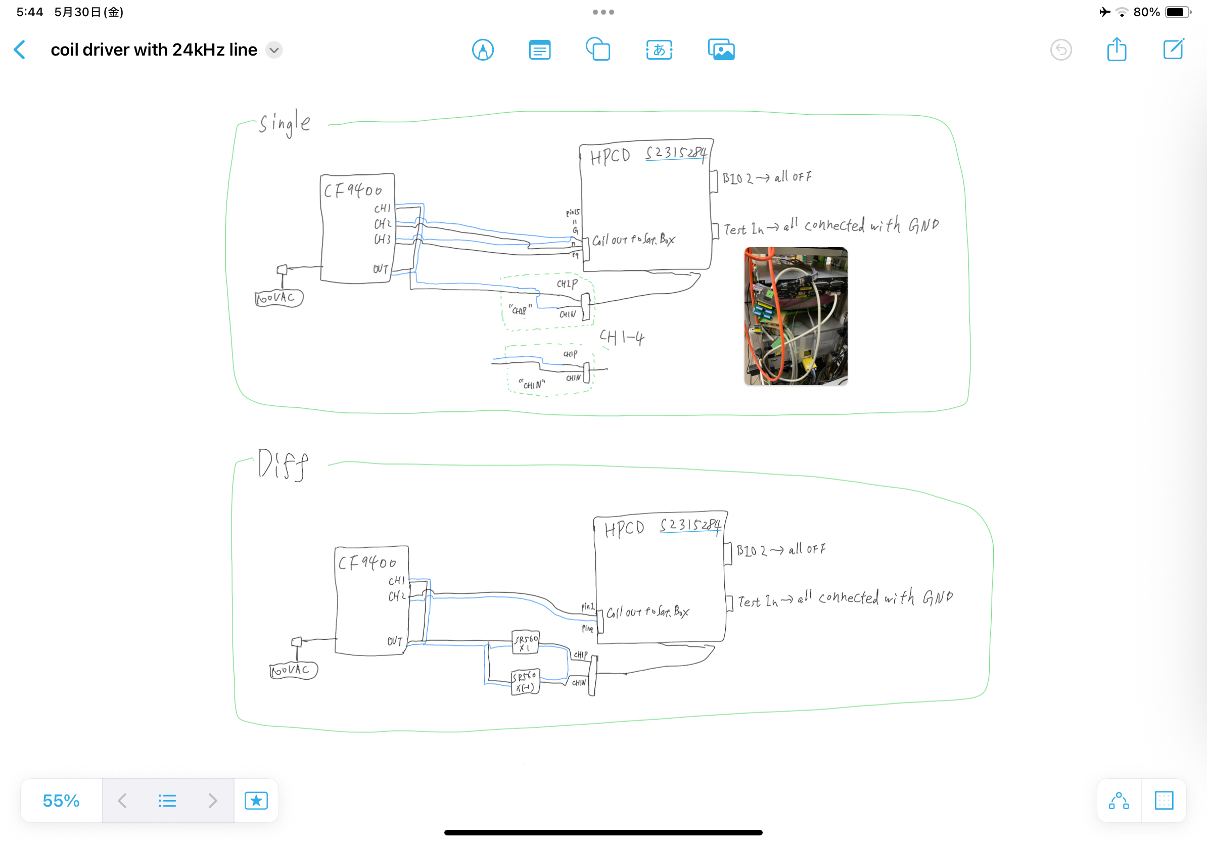
Measurement Setup
- Equipment: MokuLab Blue with a special DC power supply
- Input voltage: 0.3 V
Measurements
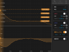
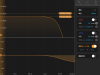
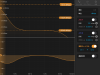
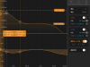
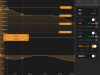
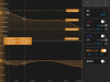
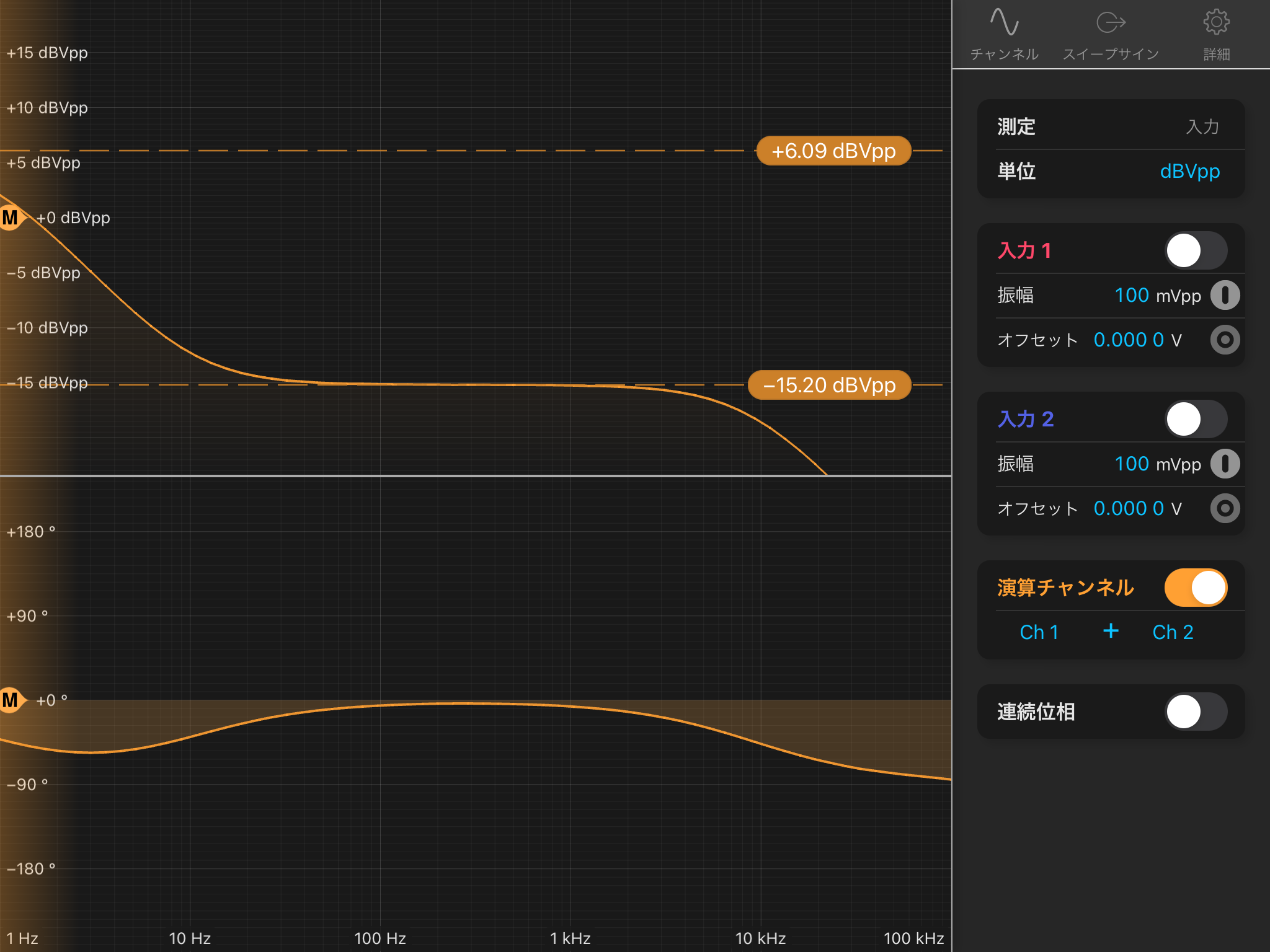
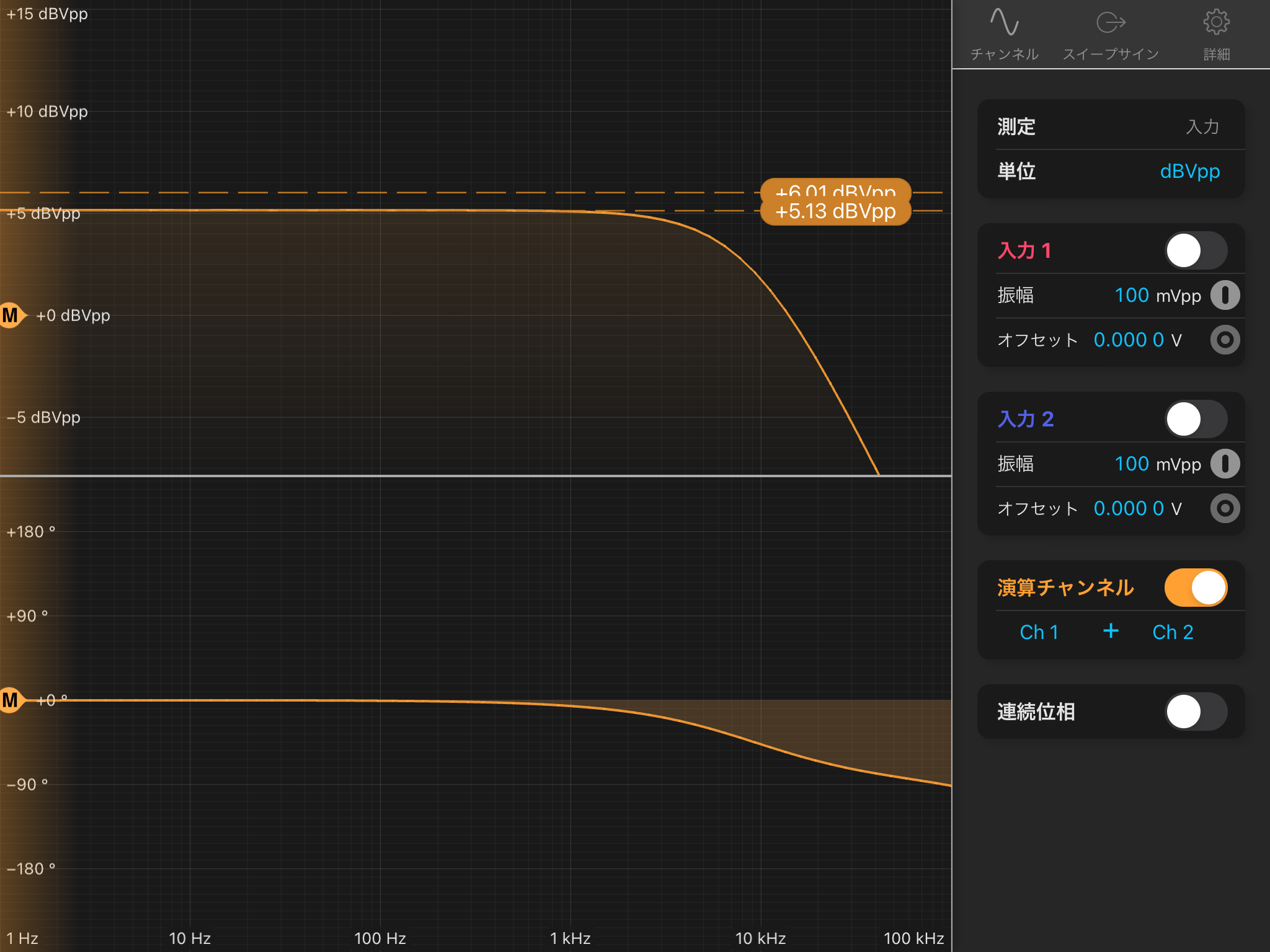
1. Transfer Function: Beacon Input to Coil Out
The measured transfer function looks reasonable.
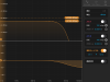
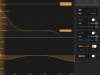
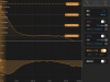
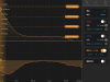
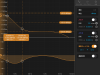
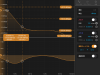
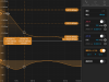
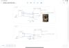
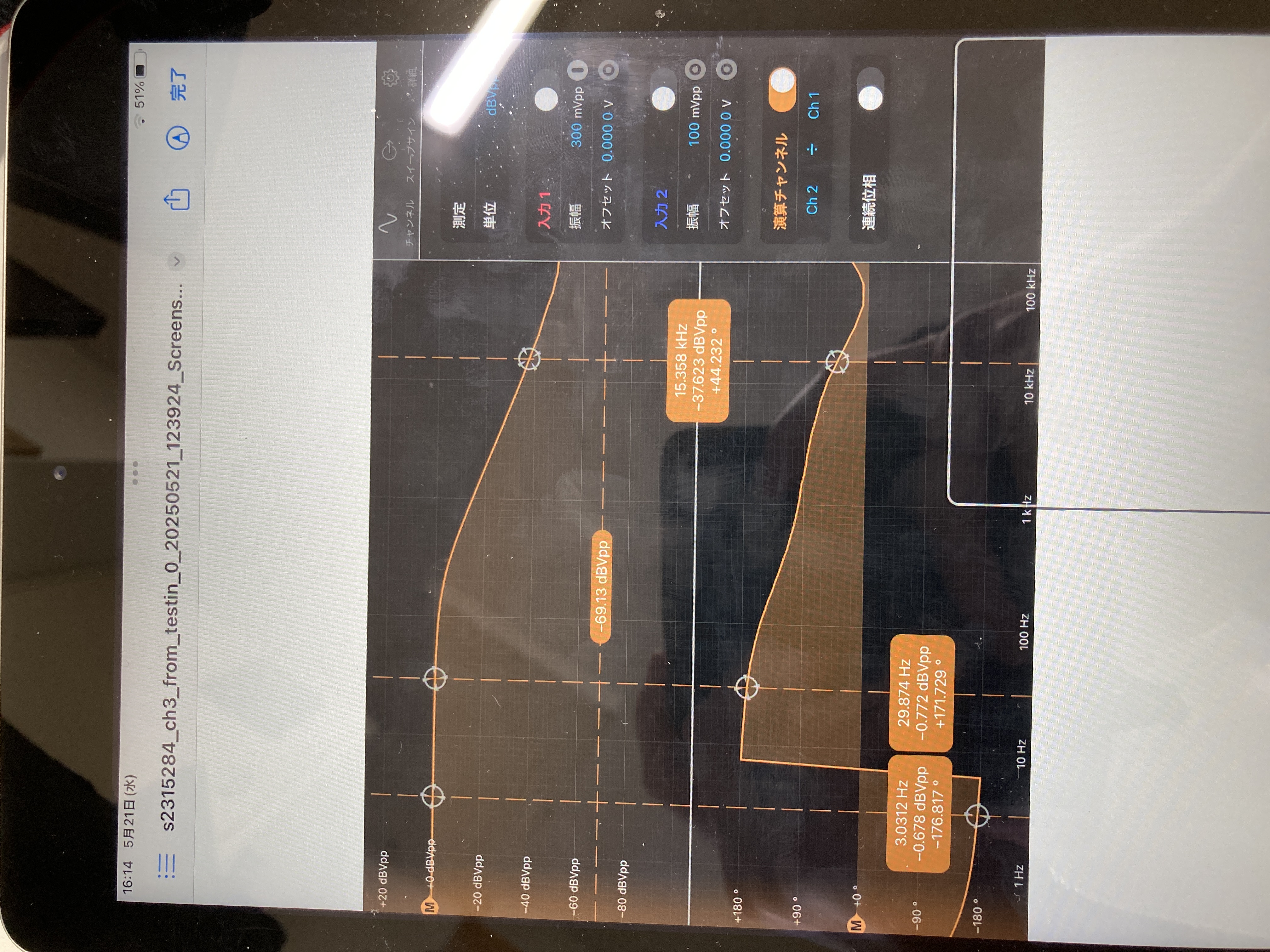
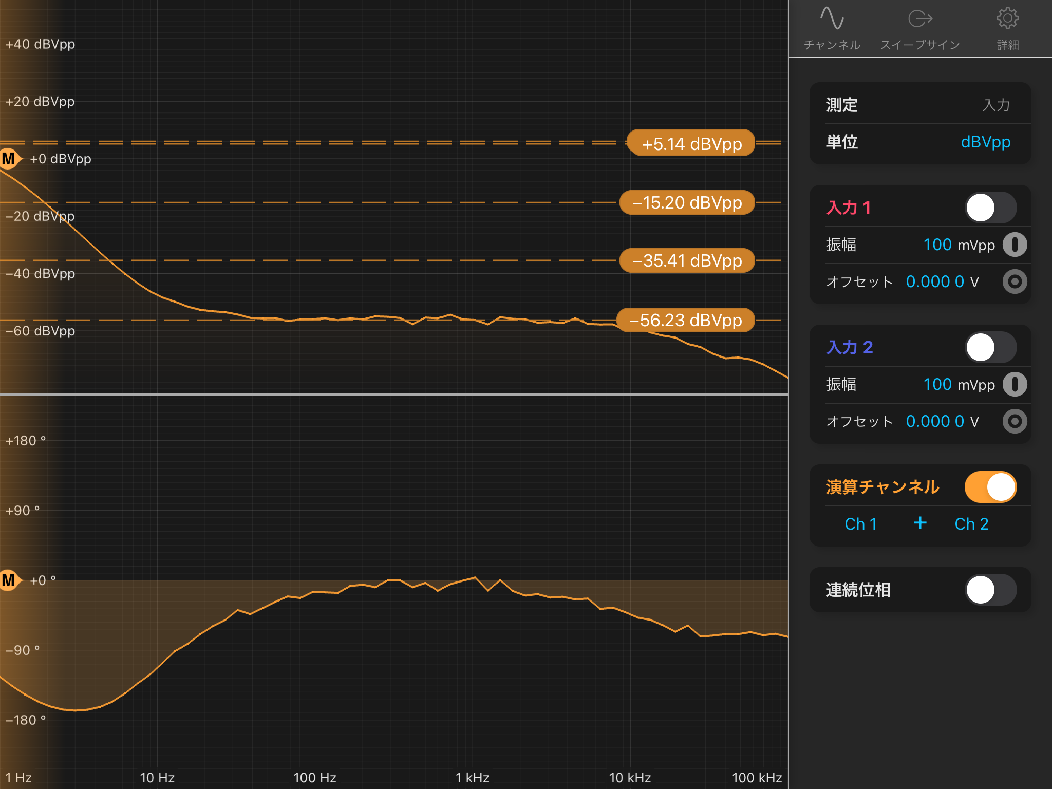
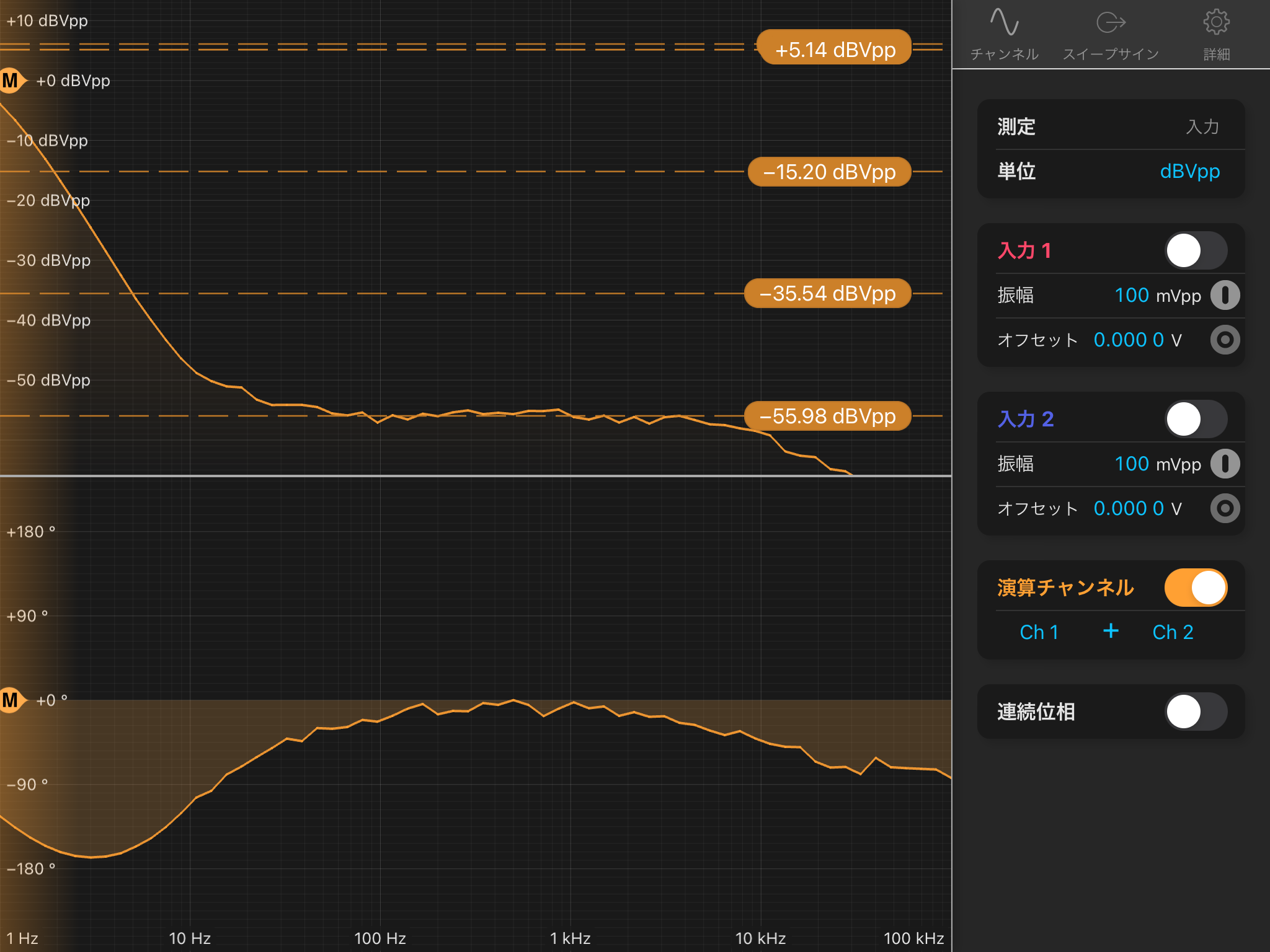
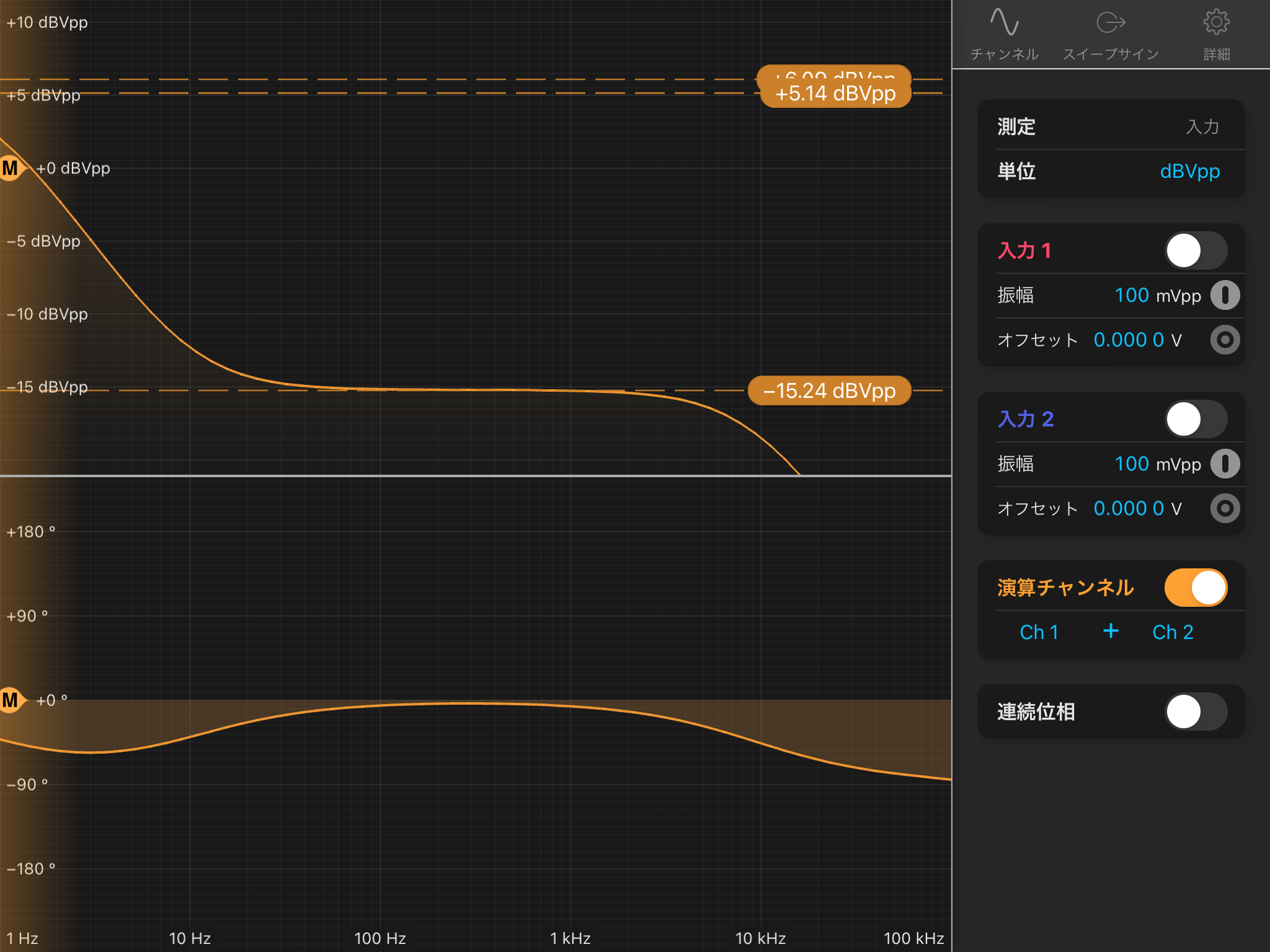
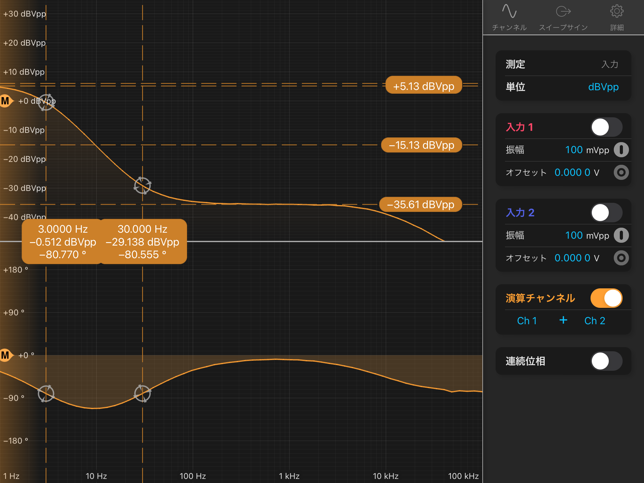
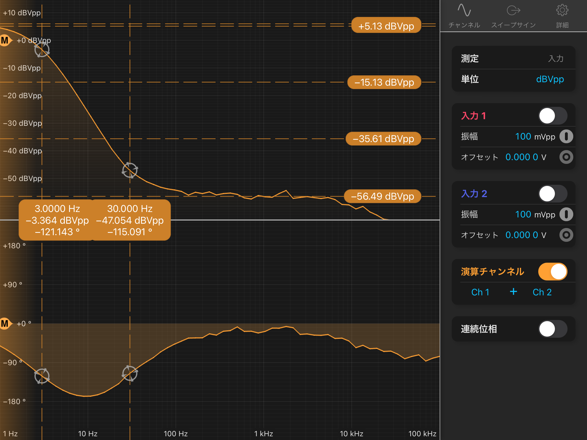
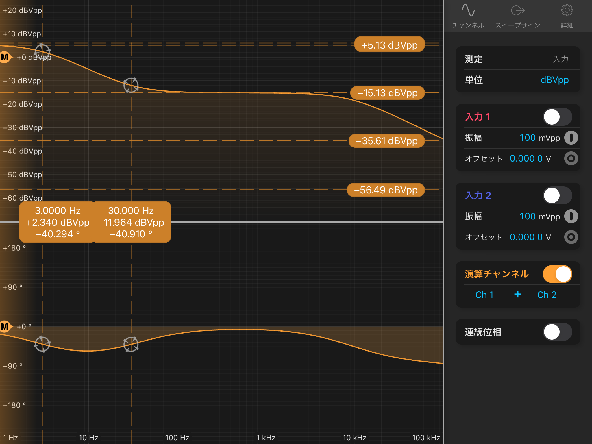
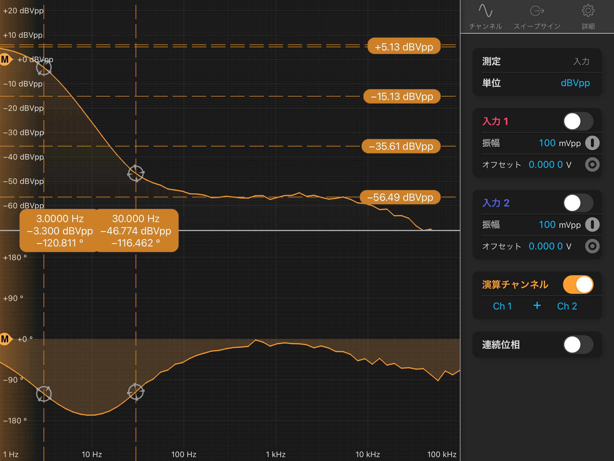
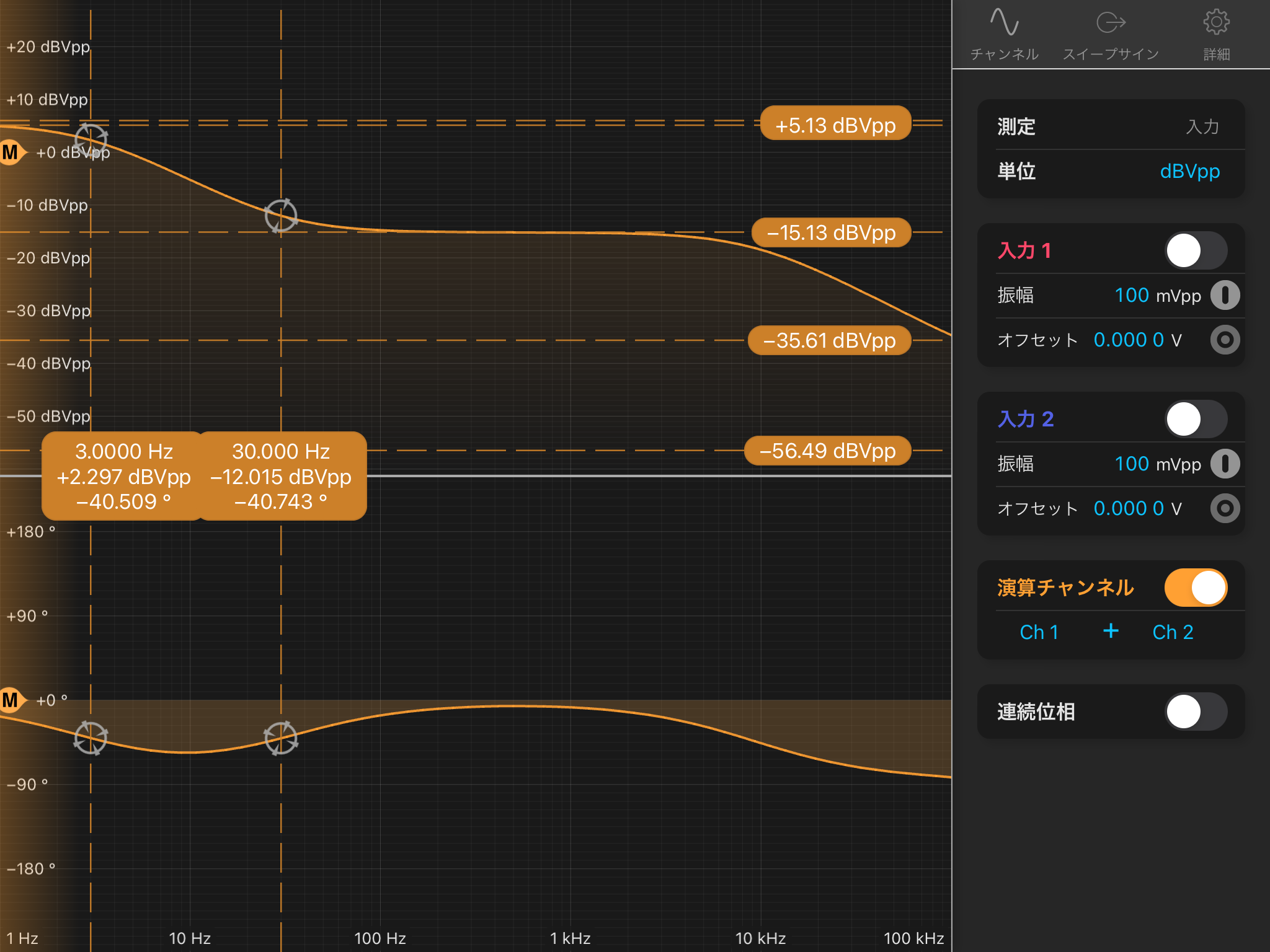
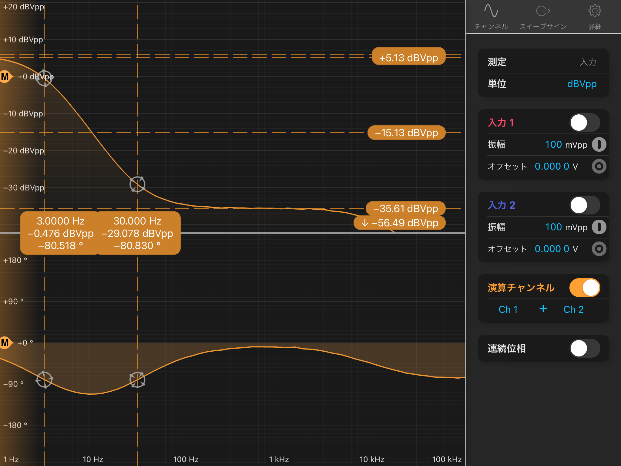
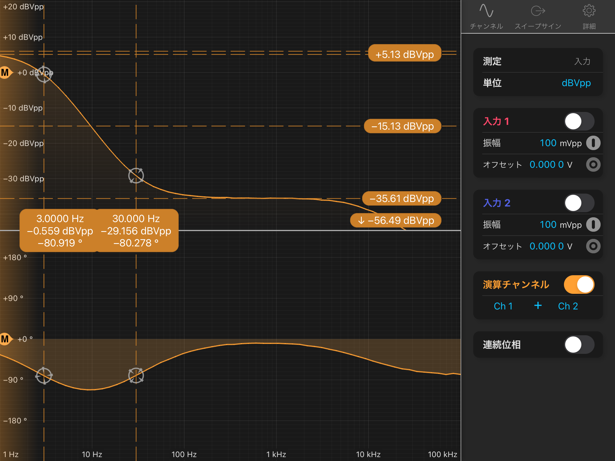
2. Transfer Function: "Test In" to "Coil Out"
- Nothing was connected to "BIO 2", so no de-whitening filter was active.
- Channel 3 showed unusual behavior — a pole(?) was observed around several hundred Hz. (Attached figure)
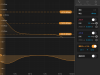
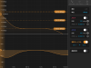
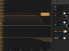
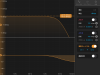
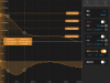
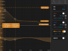
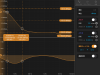
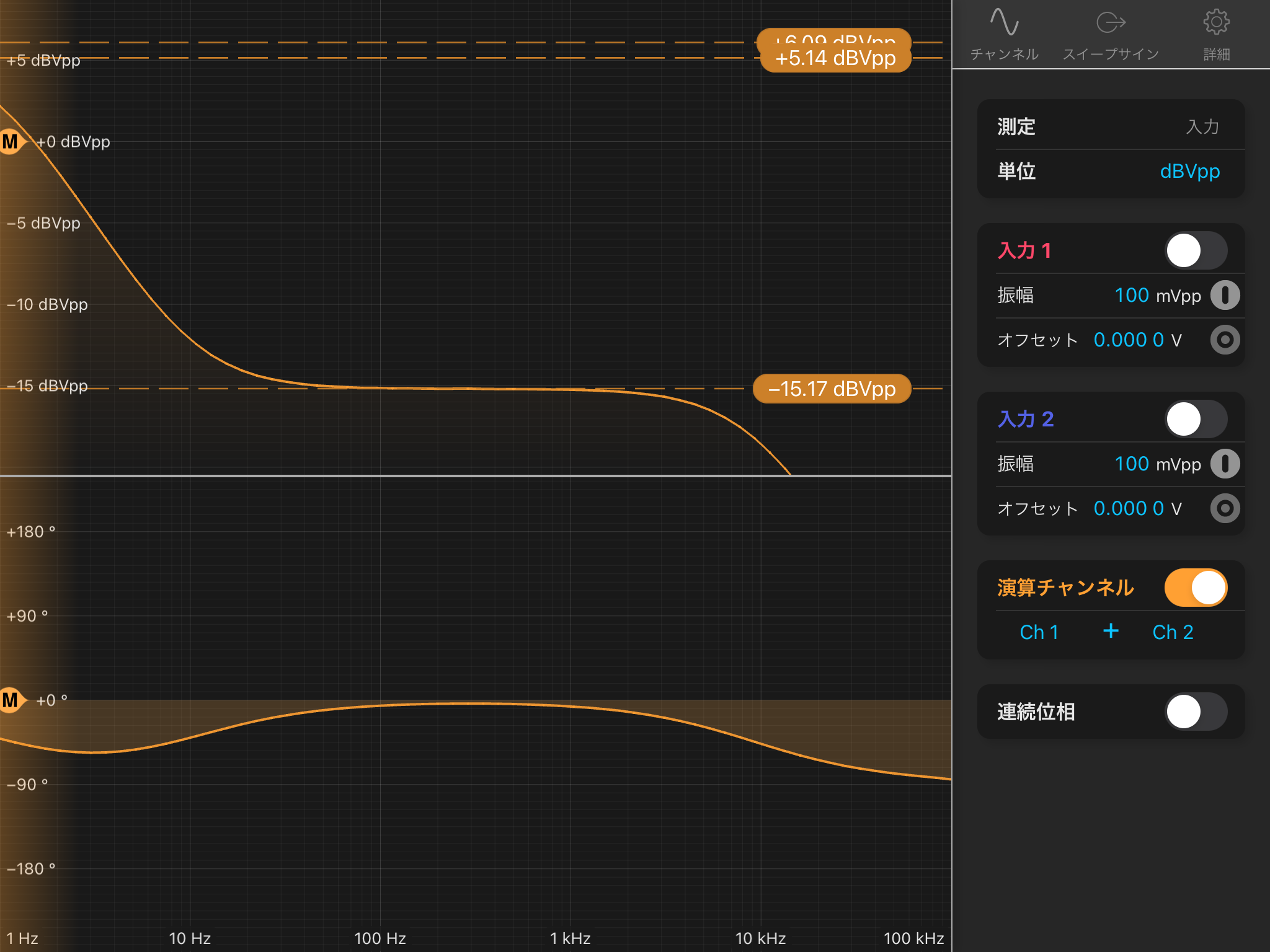
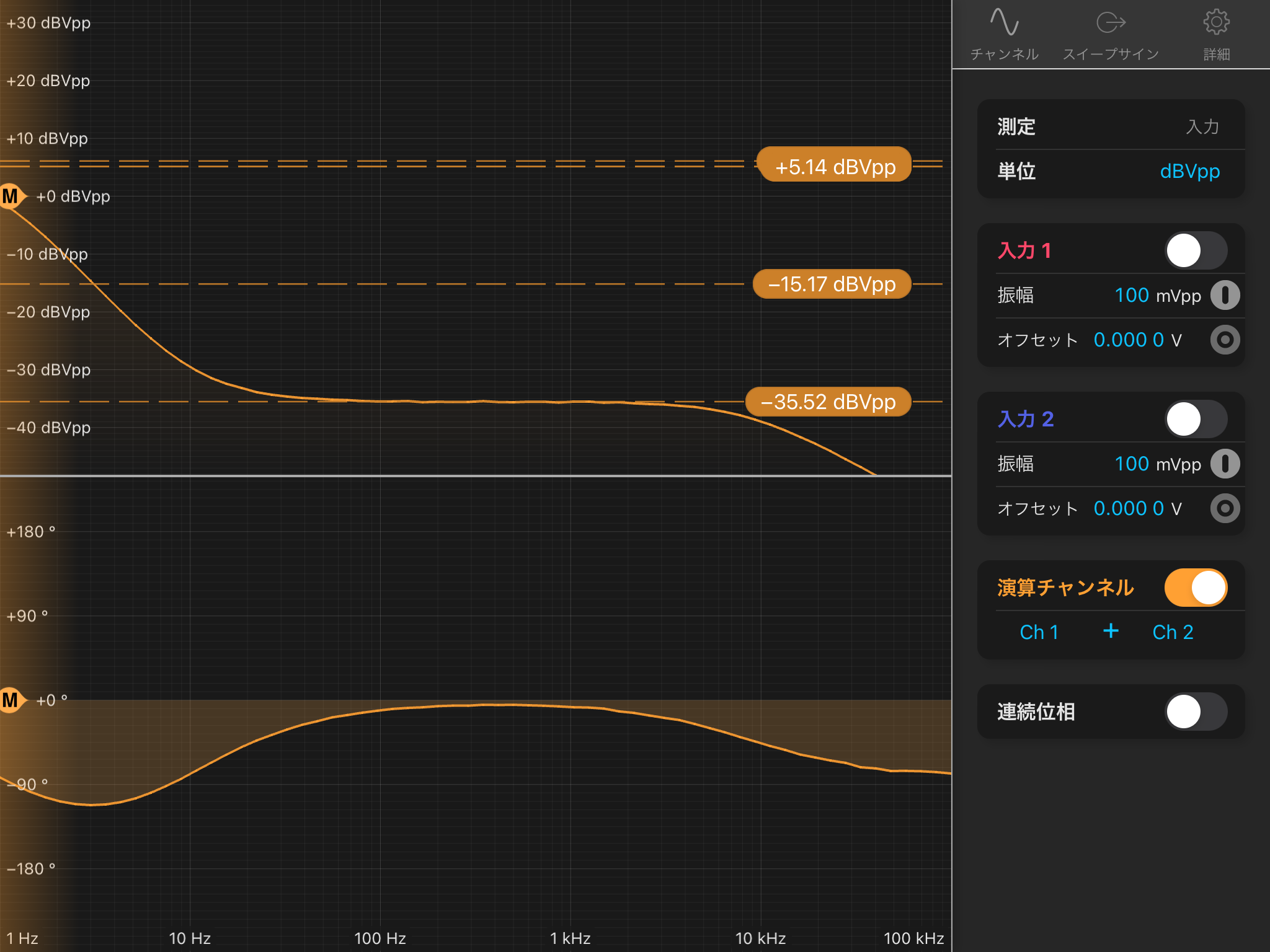
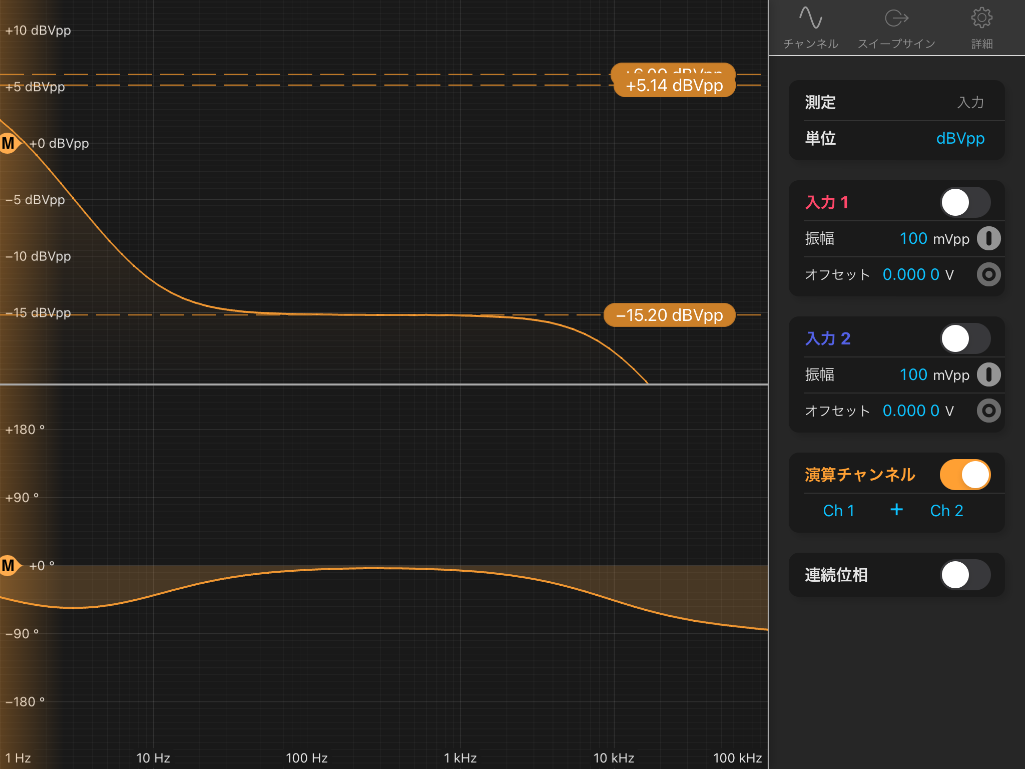
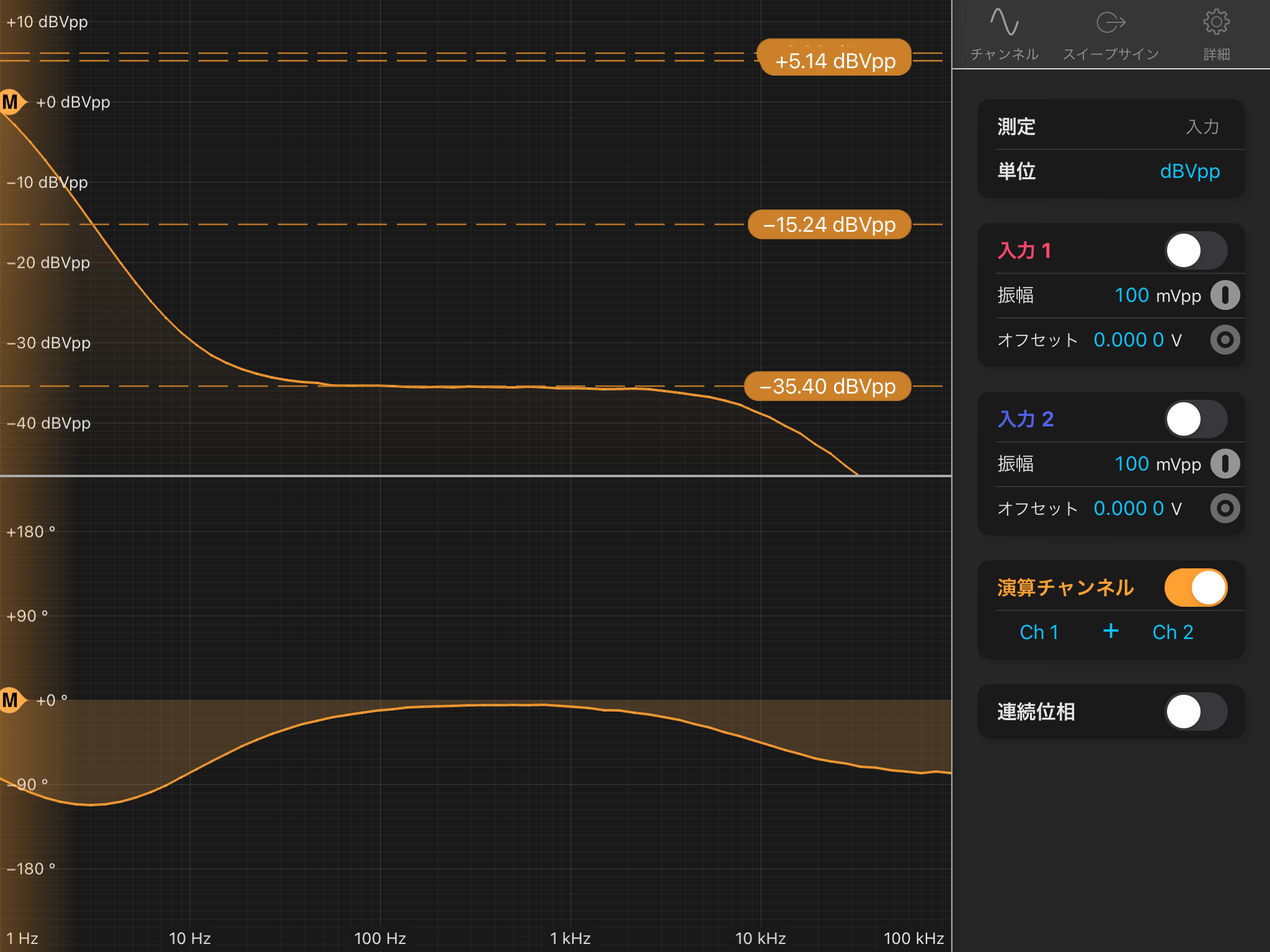
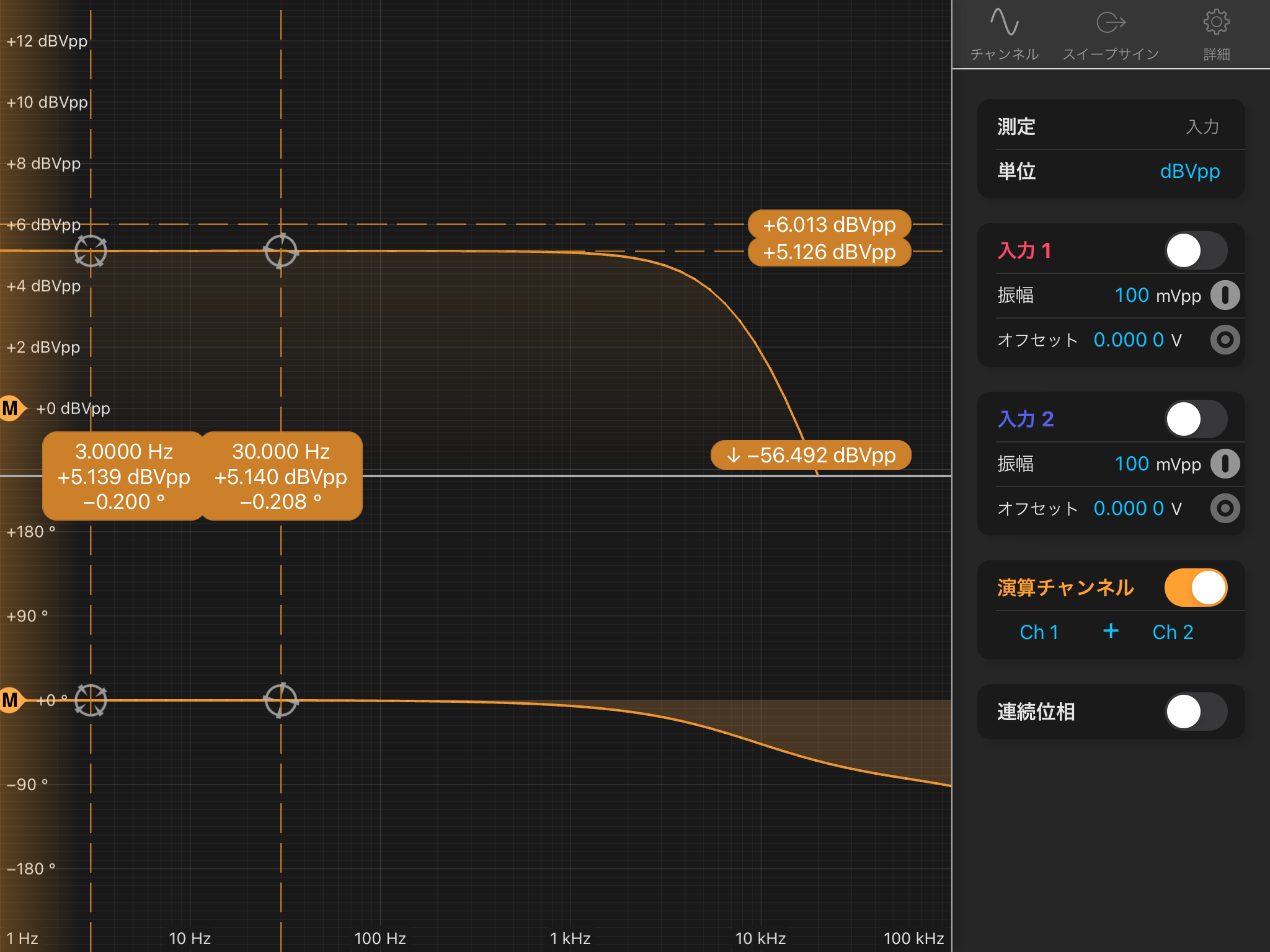
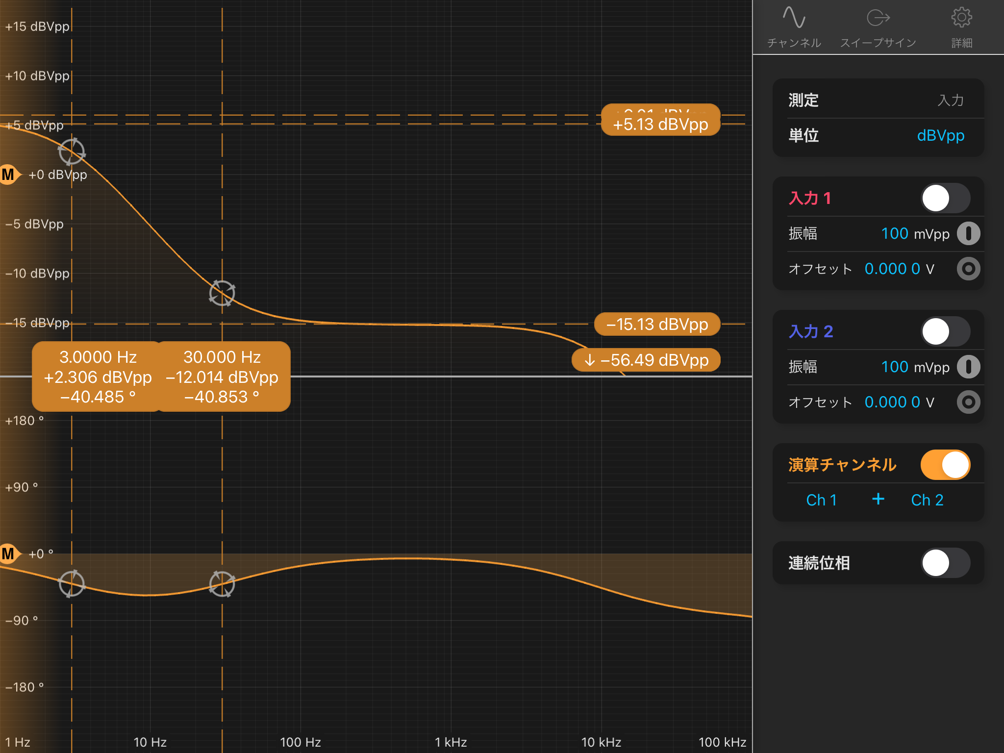
3. Transfer Function: Test In to Coil Out with BIO Setting Change
The BIO setting was changed from “2” (no filter) to “4” (three-stage filter) to observe differences. Ch 1, 2, and 4 look fine.
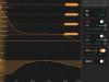
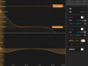
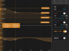
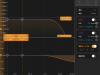
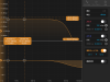
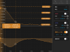
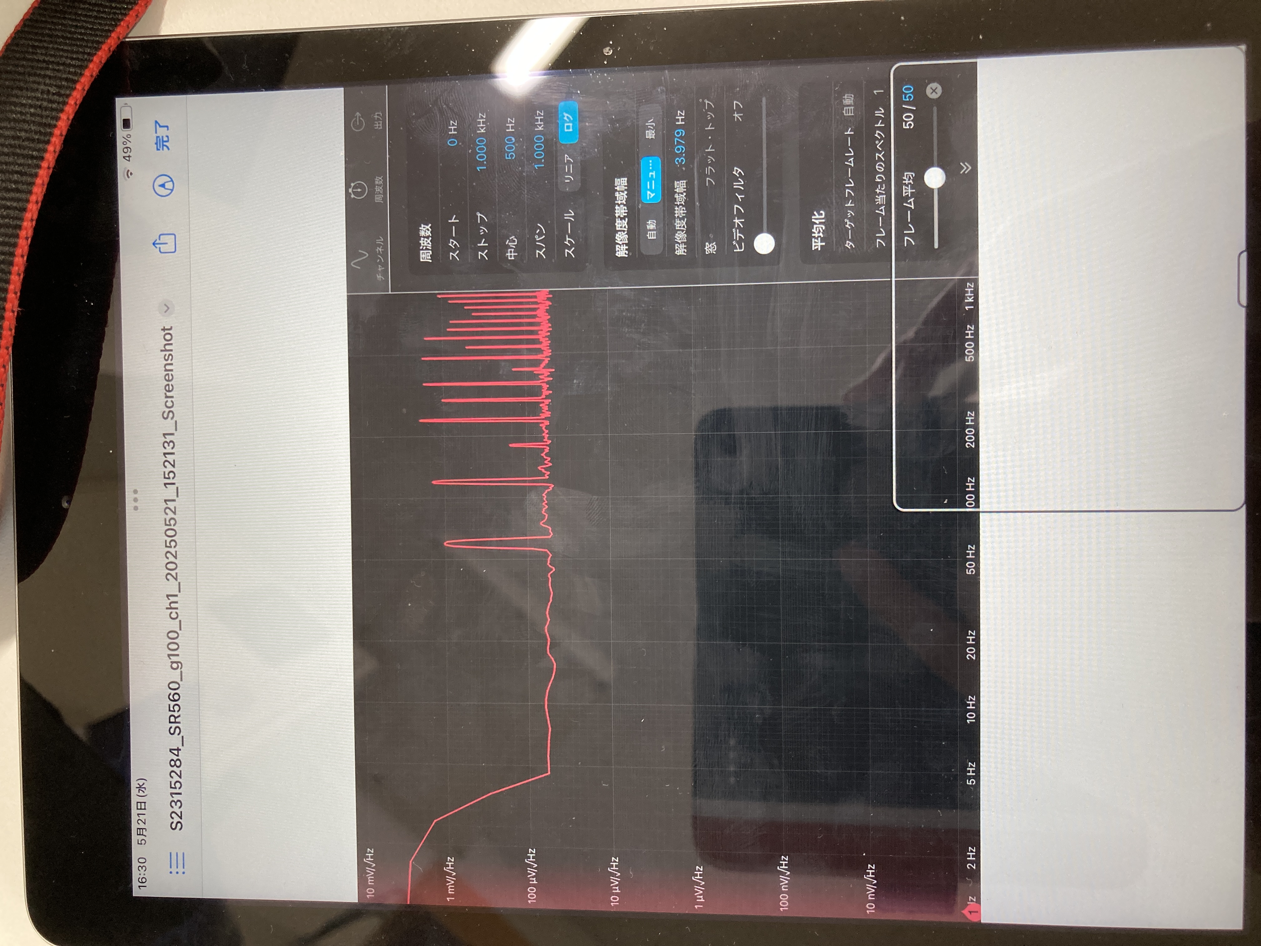
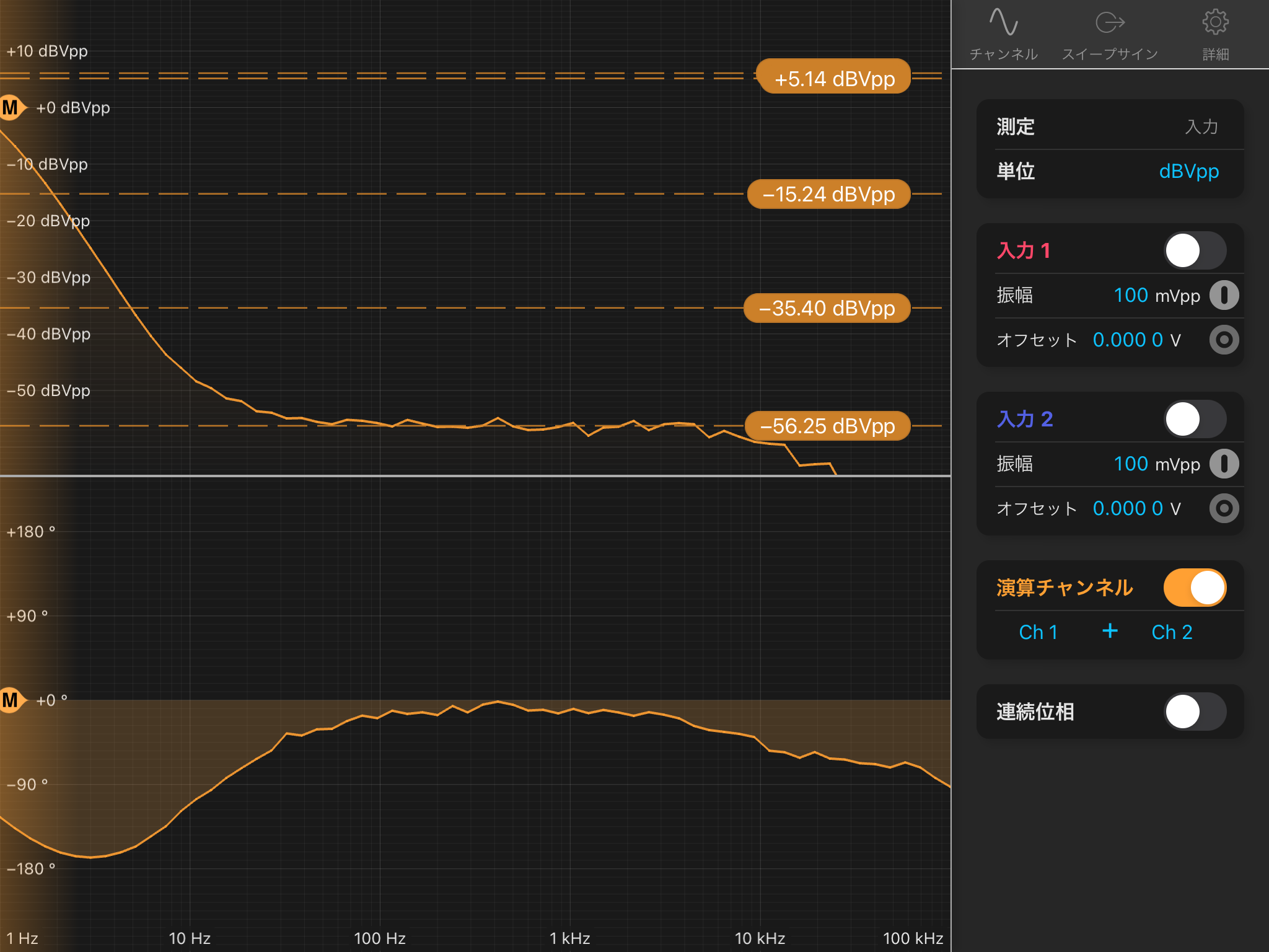
4. Noise Measurement
- The output was amplified by a factor of 100 using an SR560.
- The "Test In" inputs were terminated with 50 Ω. But the beacon input port was open.
- Background noise was measured with the input of the SR560 terminated, which was lower than the main measurement data by several tens.
- The BIO setting was “1”, meaning no de-whitening filter.
- The noise floor, accounting for the SR560 gain, is estimated to be 500 nV/√Hz. Attached one is one of the measured raw data showning about 50 uV/√Hz. (We may need to check whether the electrical GND connection was suitable.)
Results and Notes
- The circuit of Channel 2 needs to be fixed before installation at the X-end.
- The noise floor, accounting for the SR560 gain, is estimated to be 500 nV/√Hz.
- (Measurement data could not be extracted from the iPad at this time...)


