Reports 1-1 of 1 Clear search Modify search
VIS (BS)
mark.barton - 21:42 Tuesday 19 September 2017 (3385) Print this report
BS Installation

With Ohishi-san, Fabian, Enzo, Hirata-san, Yoshioka-kun and Kozu-kun.

Today:

  • We set up a 150 mm ruler on a 9.75 mm spacer (an M10 nut) to measure the keystone height. Target was 154.5-9.75 = 144.75 mm. 
  • The keystone started quite low (17.9 mm from top of the PEEK piece to the top of the PI) in its range and the keystone was also low (143.8 mm; cf 144.75 mm target). This is probably due to Enzo's tests on Friday 9/15. We found 54 mm on the FR gave 144.7 mm on the keystone, and this was about midrange. We put a pair of locknuts on the top of the shaft to prevent the PEEK piece going too high.
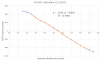
  • Fabian locked the SF and F0 keystones and measured the BF frequency. On one run of 10 cycles it was 0.443 Hz, and on a second run it was 0.454 Hz.
  • Fabian locked the the BF filter and unlocked F0. The F0 frequency on two runs was 0.208 Hz and 0.210 Hz.
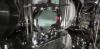
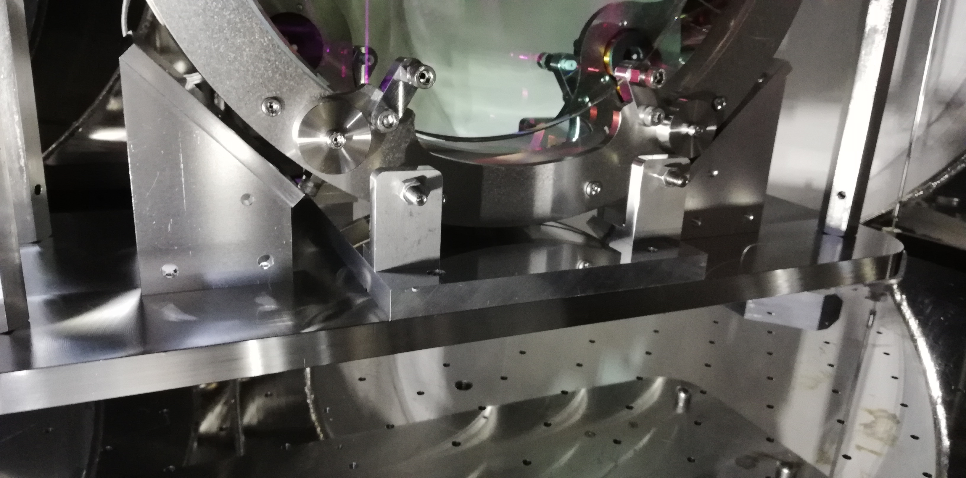
  • Hirata-san and team brought the LBB damper magnet ring halves into the tank and assembled them on top of the Cu ring, with spacers to stop the magnets being disturbed, clamps to make a sandwich of the rings, and slings to enable lifting.
  • We took the lid of the tank off, craned the sandwich of LBB damper rings up to near the top of the tank and hooked the magnet ring to suspend it. (The Cu ring is held underneath by the clamps.) We also installed the end-pieces on the thick security rods to prevent the rings falling in case of a suspension rod failure.
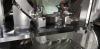
  • We investigated the PI yaw stepper motor issue some more. It turns out that the motor is correctly wired, but the odd design of the mechanism it is part of is causing it to jam. The shaft of the motor is threaded and passes through a block with a female thread. The motor is cantilevered at the end of its own shaft (with no other support for the motor or any counterweight at the opposite end at the shaft) so its weight causes the screw to bind up. Supporting the motor with fingertip pressure allows it to run freely, but that is not practical for actual use. We will think about a redesign. 
  • We checked the height of the F0 yoke. The CAD has the top of the PEEK coil former at 37.5 mm above the recess in the top of the PI and we measured 36 mm. The LVDT reading was already quite near zero for the keystone at nominal, so we decided not to adjust the yoke.
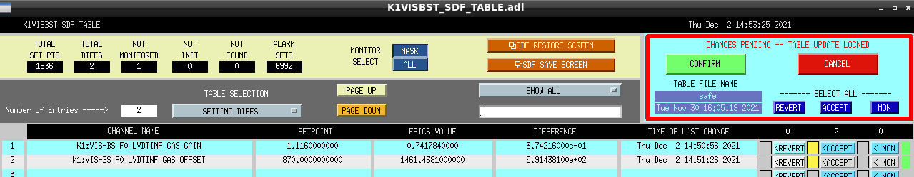
  • We did a calibration of the F0 LVDT. See separate klog by Enzo.
Comments to this report:
enzo.tapia - 11:10 Wednesday 20 September 2017 (3389) Print this report
Data of the calibration of F0 LVDT.
Non-image files attached to this comment
fabian.arellano - 15:05 Wednesday 21 November 2018 (7072) Print this report

With Fujii-kun.

This post is related with entry 7066. Is related to the investigation of the large drift of the suspension, especially in F0.

Fujii-kun notifed that the calibration factor of the F0 LVDT seemed unusual. I checked the original Excel file and I have found the factor (2.174 µm/cnt) to be incorrect. I have the following comments:

  1. The plot was made with the keystone position data formated as text not as numbers. That's the reason the data in the horizontal axis does not show the correct data.
  2. It also happens that the axes labels are the other way around. Nevertheless, the calibration factor which was written in the medm screen was calculated considering the keystone position in the horizontal axis and the LVDT output in the vertical one.

After the correction I got a calibration factor of 1.1285 cnt/µm, which becomes 0.8861 µm/count for the medm screen. This value has been corrected in the medm screen already. On December we will have access to the suspension and we should double check the offset value.

Non-image files attached to this comment
mark.barton - 16:43 Wednesday 19 December 2018 (7440) Print this report

On 2018-12-19 I found that the gain in the BS F0 LVDTINF filter had reverted to the old, incorrect value of 2.174 µm/ct, presumably because a safe.snap had not been done after it was corrected and there had been at least one reboot since. I reentered the corrected gain of 0.8861 µm/ct and did a new safe.snap.

fabian.arellano - 17:28 Wednesday 01 December 2021 (19045) Print this report

With  Hirata-san

F0  LVDT  calibration

Summary:  we  calibrated  the  F0  LVDT after  we  replaced  the  LVDT  driver  card.

Because we replaced the LVDT card (see 18933 and related entries) due to the problem with the F1 LVDT, we calibrated the F0 LVDT again. The following are the highlights:

  • The 3D CAD nominal position of the keystone is 16.5 mm below the upper plate. See  entry  5314  for details (the  entry  is  for  SR3,  but  it  applies  to the  BS  also).
  • Because  the  reference  point,  from  which  we  measured  the  position  of  the  keystone,  is  above  the  keystone,  the  calibration factor  calculated  with  this  data  is  negative.  Nevertheless,  we  when  did  installation,  we set the polarities in hardware such  that an upward displacement produces a positive LVDT output. Therefore, the calibration factor that should be written in the medm screen should be positive.
  • I was able to move the keystone below the nominal position 3 mm only because the RM came very close to the security structure below. See pitcures.
  • The directory where the data is stored is: /kagra/Dropbox/Subsystems/VIS/TypeBData/BS/F0_calibration/
  • The result of the fit is:
    • Slope: -1348.1 cnt/mm (with the sign given by the plot).
    • Linear range: 6 mm in total (from 12.5 to 18.5 mm in the plot); with respect to the nominal position, and with the correct sign, it is [-2 , 4] mm.
Images attached to this comment
Non-image files attached to this comment
fabian.arellano - 14:54 Thursday 02 December 2021 (19057) Print this report

Summary: After the calibration of the F0 LVDT, I wrote the appropriate calibration factor and offset in the medm screen.

  • The slope from the plot is 1348.1 cnt/mm, which becomes 0.7418 um/cnt for the medm screen.
  • The LVDT output at the 3D CAD nominal position of the keystone (16.5 mm) is -1461.438 cnt, therefore, the offset to write in the medm screen is 1461.438 cnt.
  • After the change I accepted the new values in the SDF.
Images attached to this comment
Search Help
×

Warning

×