With KTanaka, Ushiba, Michael,
Summary
- At first, we adjusted PLLY TEMPY_bias to lock the ALS-Y loop.
- Then, after the initial alignment for the Xarm, we performed the cavity scan, and found the resonant frequencies between carrier and f1, and f2 were not too close.
- But, we changed the LO frequency by -5Hz to make more margin. (We confirmed that these 3 don't have overlap.)
- After this work, we took the alignment for Xarm, Yarm, OMC, and PRMI, and locked PRFPMI.
- Then DC centering and adjustment of WFS signals were performed.
Details
- PLLY
- By whatching
K1:ALS-Y_BEAT_ERR_OUT_DQ, change the TEMPY_bias to lockALS_PLLY. - CommissioningDock -> LSC -> ALS OVERVIEW -> Left bottom
- Procedure
- Request
DOWNtoALS_PLLY - Change TEMPY_bias with monitoring
K1:ALS-Y_BEAT_ERR_OUT_DQ - Request
PLL_LOCKEDtoALS_PLLYguardian
- Request
- TEMPY_bias:
- -0.440V -> did not work.
- -0.545V -> Locked
- By whatching
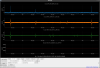
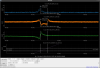
- Xarm cativy scan
- Xarm alignment adjustment was performed by Yokozawa-san
- Ref: klog-30825
- Request DOWN to Xarm
- Change Y offset of ETMX TM SET: -18.1 -> -22.1
- Requested
ALS_LOCKEDto XARM - Changed the gain of FB of MCL to be 1 as soon as posible.
- With reference to
ENGAGED_ALS_CARMstate in "LSC_LOCK" guardian, we performed the following steps- Turn ON "FM4" in FILT_MCL
- Turn ON "IN2" in CMS(Common mode survo) IMC survo (CommissioningDock -> Common Mode Servos -> IMC ->
K1:IMC-SERVO_INsEN_SW_ON) - Turn OFF "FM2" in FILT_MCL
- Change "IN2" gain to 24 in CMS_CARM survo. (
K1:LSC-CARM_SERVO_IN2GAIN) - Turn ON "COMBOOST" in CMS_CARM survo. Turn ON 1 -> Turn ON 2.
- Turn ON "FM5" in FILT_MCL
- This time, as we want to see are f1 and f2, we did not need to change the laser power like what Hirose-san's group did.
- Change the offset of SUMMING SURBO from -27000 to +27000 with 300 seconds RAMP time.
- Open SUMMING NODE CMS
- Right click -> Execute -> FB screen -> click
SLOWOUT_CALI - Set 300s to the RAMP time
- Change the offset from -27000 to +27000
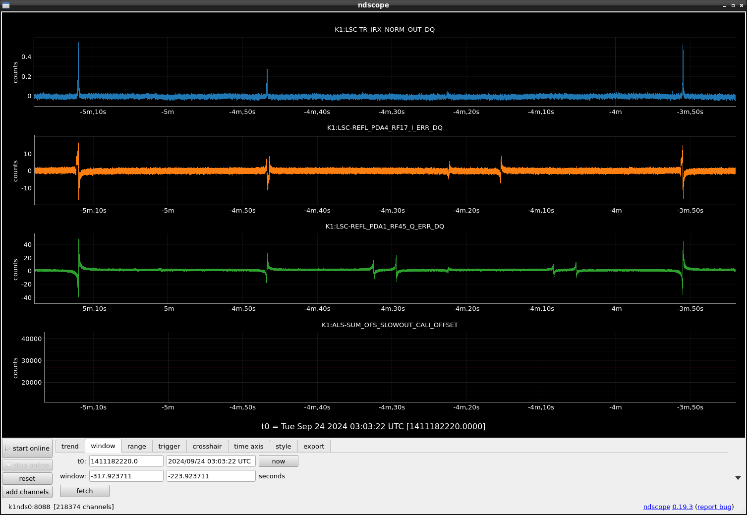
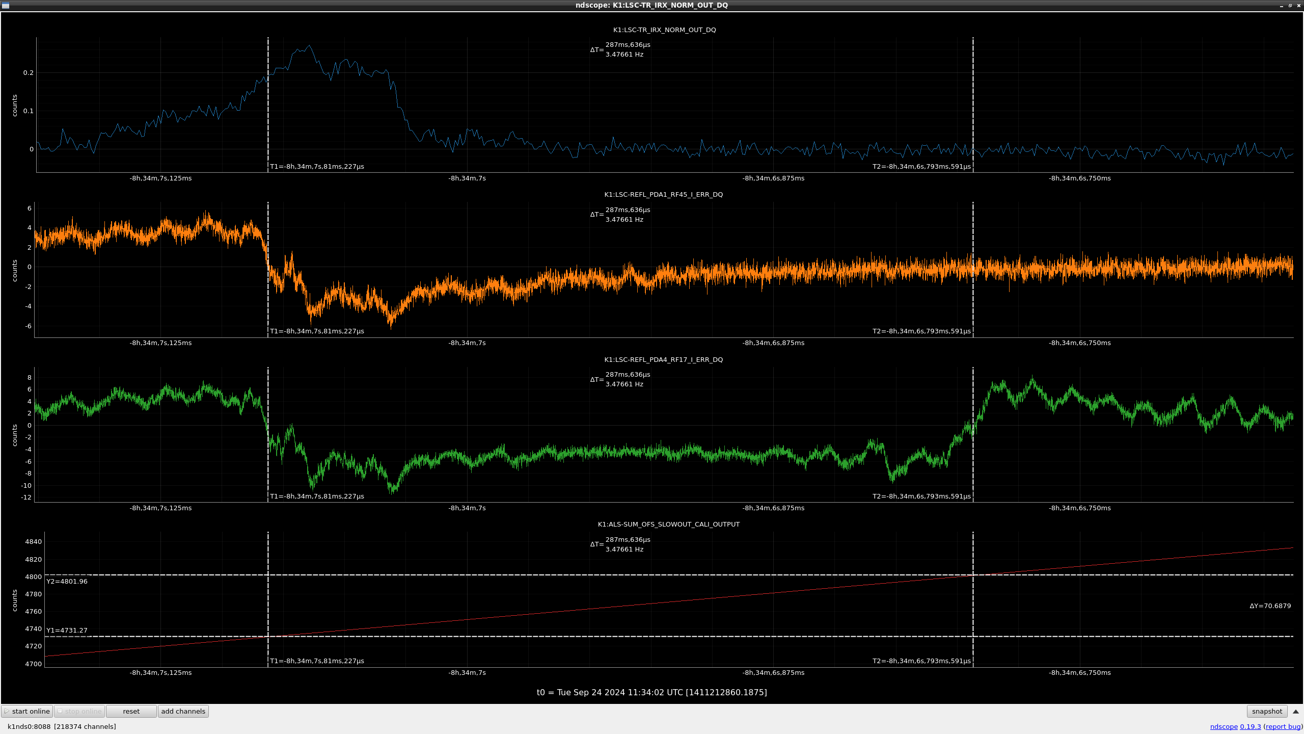
- Monitor the flash with
K1:LSC-TR_IRX_NORM_OUT_DQ,K1:ALS-SUM_OFS_SLOWOUT_CALI_OUT_DQ, and cameraTMSX_IR- from 27000 to -27000
- 1st: TEM00 (offset: 25193)
- 2nd: TEM01 (offset: 11405)
- 3rd: TEM00 (offset: 5363)
- 4th: TEM01 (offset: -8268)
- 5th: TEM00 (offset: -14155)
- Make the alignment back: Change Y offset of ETMX TM SET from -22.1 to -18.0
- Scaned it again
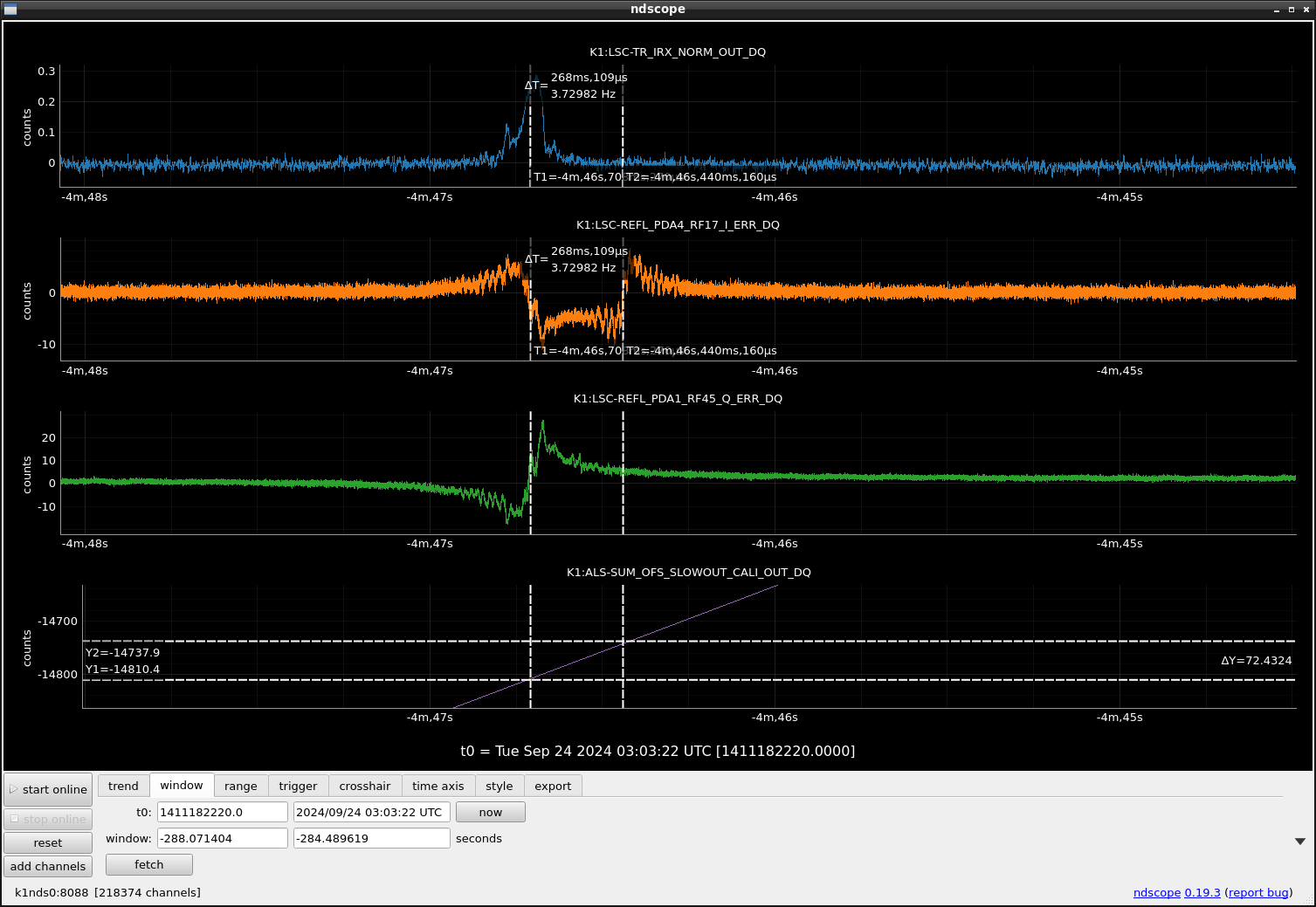
- Figures: fig1, fig2
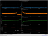
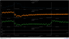
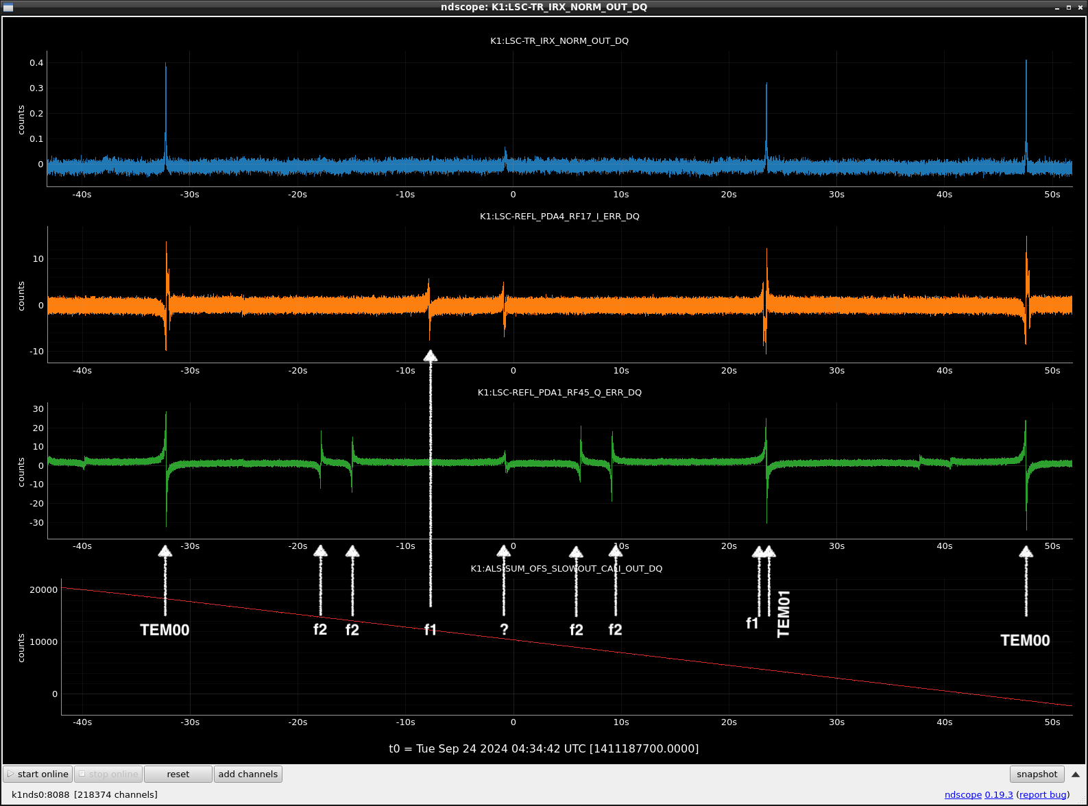
- We change the modulation frequency.
- 5.624 369 113 MHz -> 5.624 364 113 MHz
- Check each peaks
- df between TEM00 and TEM01 of carrier: 5669.5 [counts]
- df between TEM00 and TEM01 of carrier: 13779.6
- df between TEM00 and unknown of RF45: 1700.8
- df between TEM00 and unknown of RF45: 2466.2
- df between TEM00 and unknown of RF45: 3394.2
- df between TEM00 and unknown of RF45: 4159.6
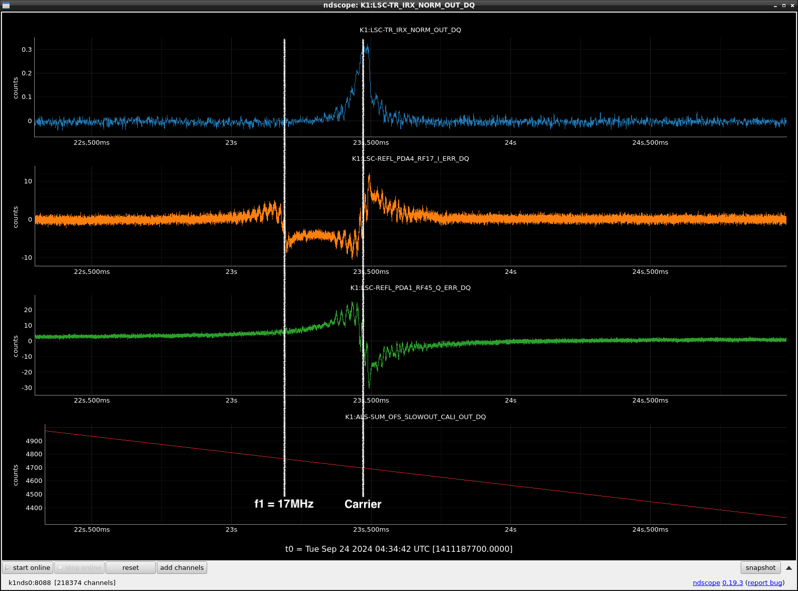
- We can not see any overlap. So let's use this modulation freq.
- Figures: fig3, 4
- Alignemnt adjustment
- Adjustment of ETMY alignment
- State at
IRY_LOCKED - P: -30.2 -> -34.1
- Y: 3.9 -> 3.1
- State at
- Adjusument of BS
- State at ALIGNING_YARM
- P: 10.7 -> 14.7
- Y: -14.7 -> -16.3
- OMC
Close GRXandClose GRY- Requested
IRX_LOCKED - Requested
ALIGNING_TO_OMC - Open he GRX, GRY shutters.
- PRMI
- Change
total(deg)to 176. - Requested
ALIGNING_PRMI - Aalignment adjustment for PRM
- State: requesting
ALIGNING_PRMI - See POP_PDA2_RF90_I_ERR_DQ
- P: 39.0 -> 2.0
- Y: -56.6 -> -56.6
- State: requesting
- Change
- Adjustment of ETMY alignment
- Try lock PRFPMI
- Requested
ENGAGE_WFSDC-> locked.
- Requested
- WFS alignment adjustment
- DC centering
- Use REFL_WFS picomotors
- Change set point on
ASC_SERVO_VIEW_ARM.adl- K1ASC-DHARD_P
- K1ASC-CHARD_P
- K1ASC-DHARD_Y
- K1ASC-CHARD_Y
- DC centering
