Abstract:
I measured transfer functions of all filters that can be switched from DGS in PLL CMS (S2415893).
Though Common BOOST 2/3 filter seem to have slightly lower zeros, it is probably acceptable.
Detail:
To replace the noisy PLL circuit (klog18014), I tested spare PLL CMS at test bench.
What we did:
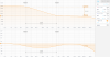
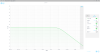
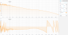
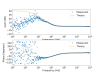
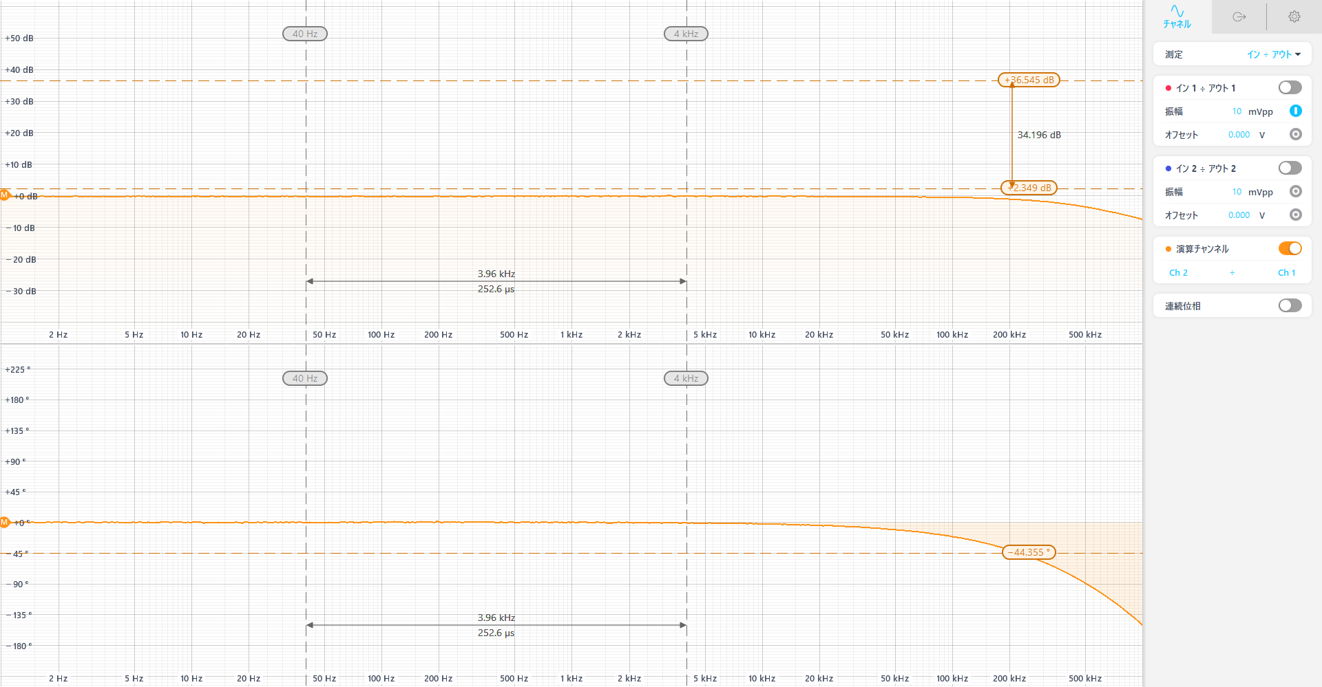
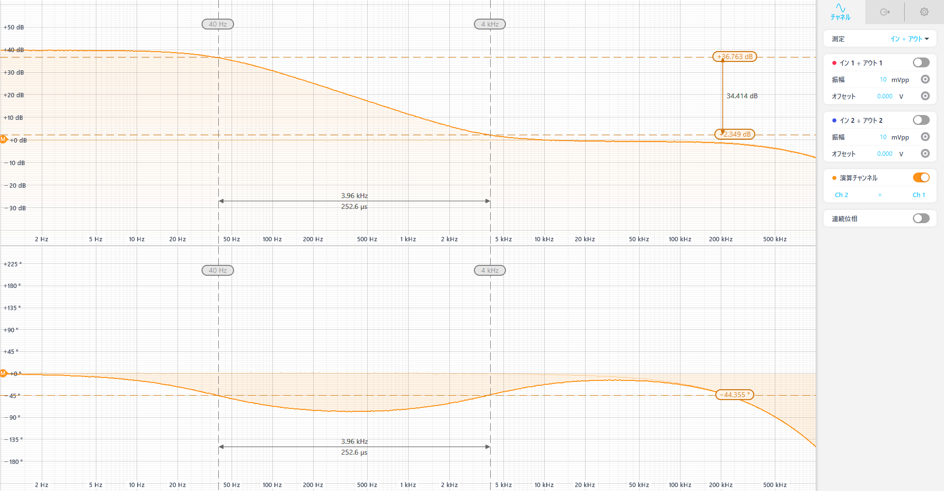
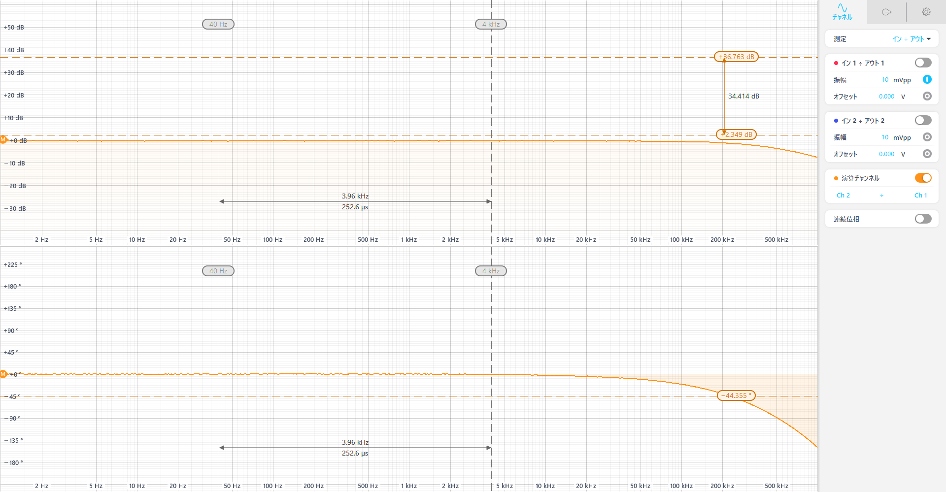
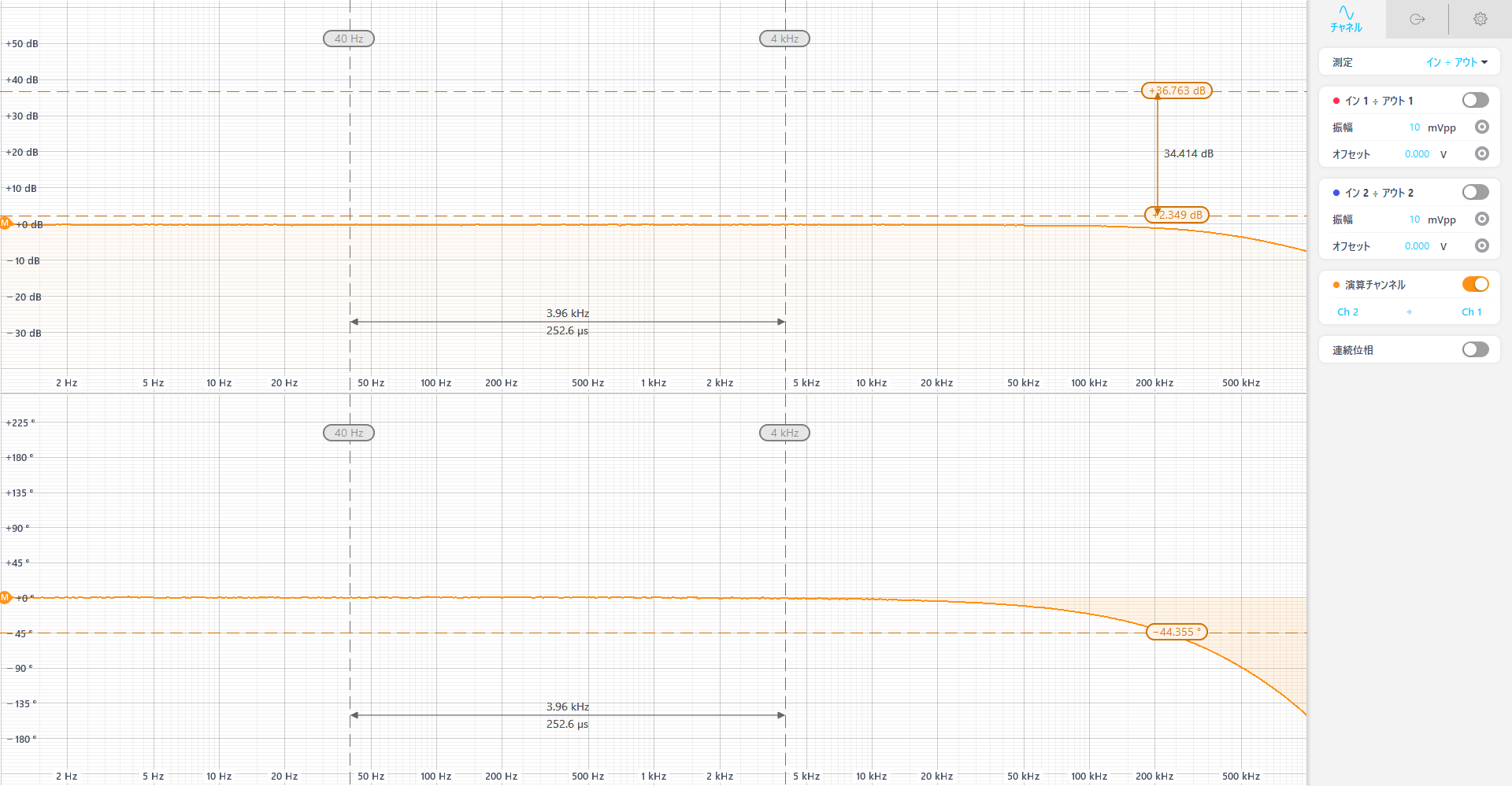
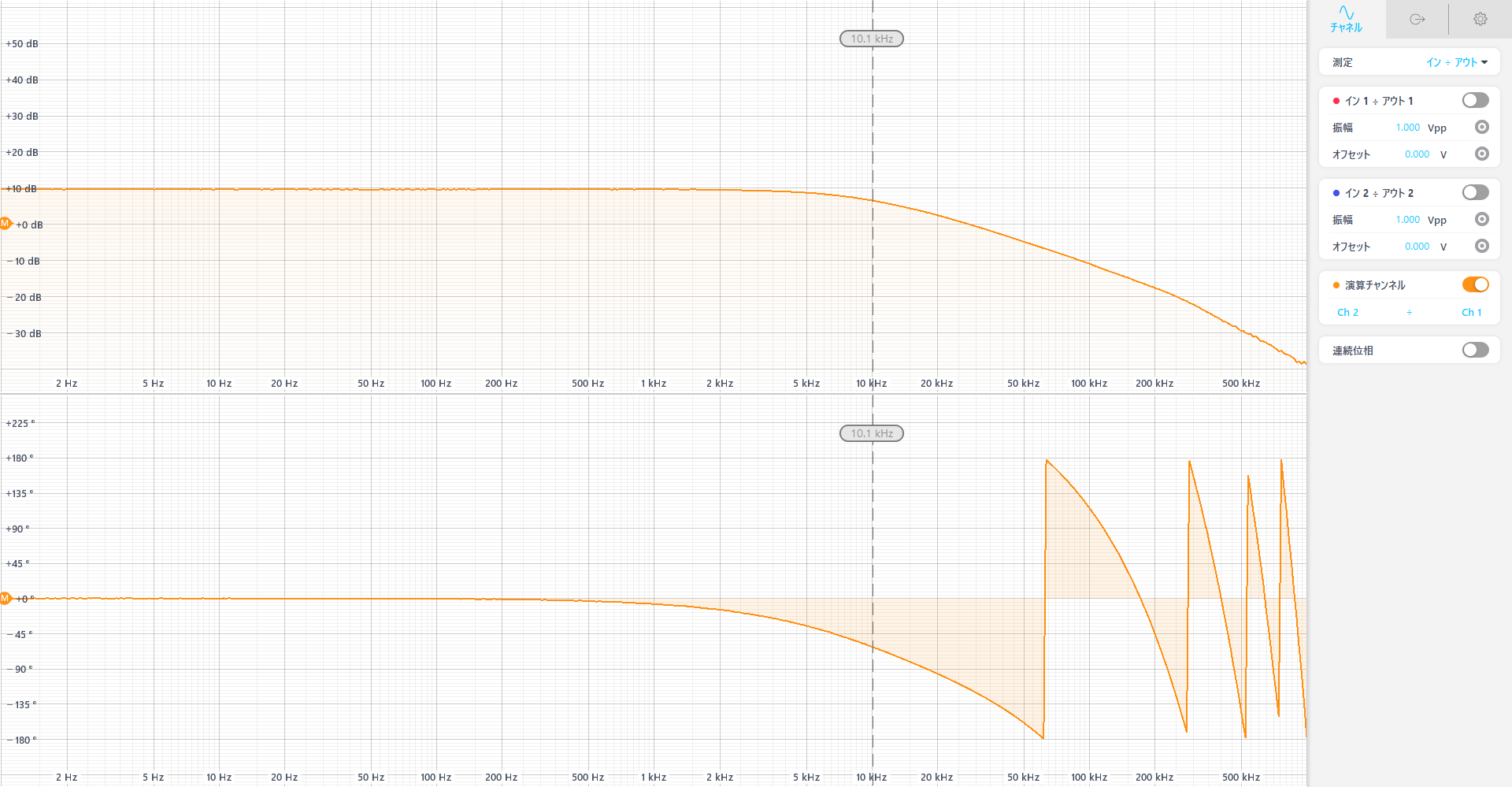
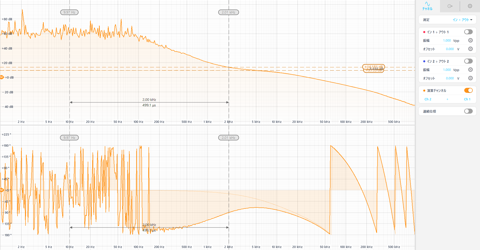
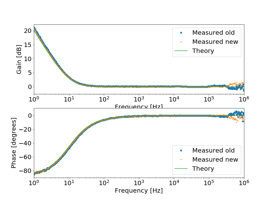
1. Measure TF from IN1 to SLOW_OUT without turning on the filters
The last low-pass filter on the slow path should be modified, and it should have 500kHz cut-off frequency.
Figure 1 shows the result.
Though it has an additional phase delay at high frequency but should be acceptable because UGF of PLL loop is about 30kHz.
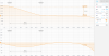
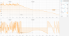
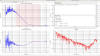
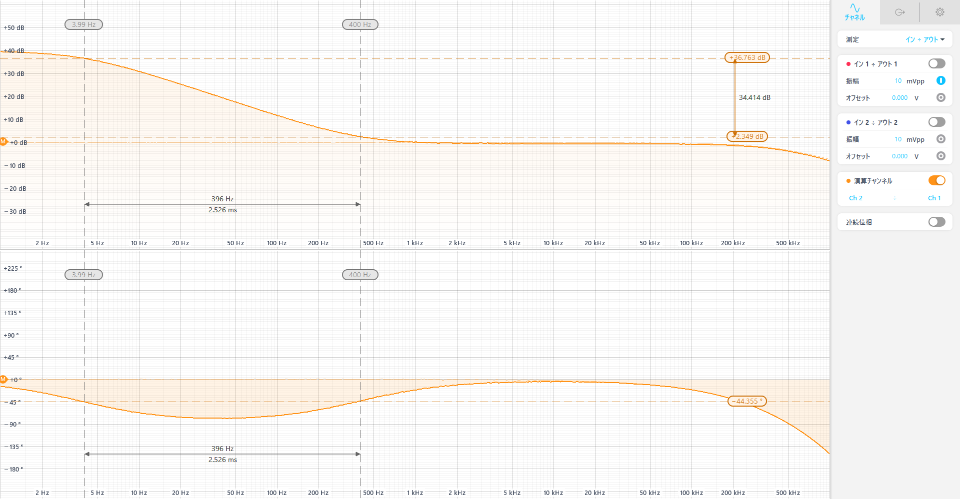
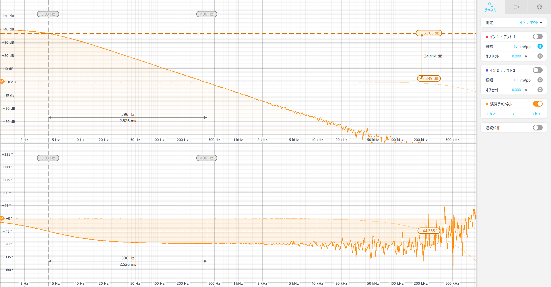
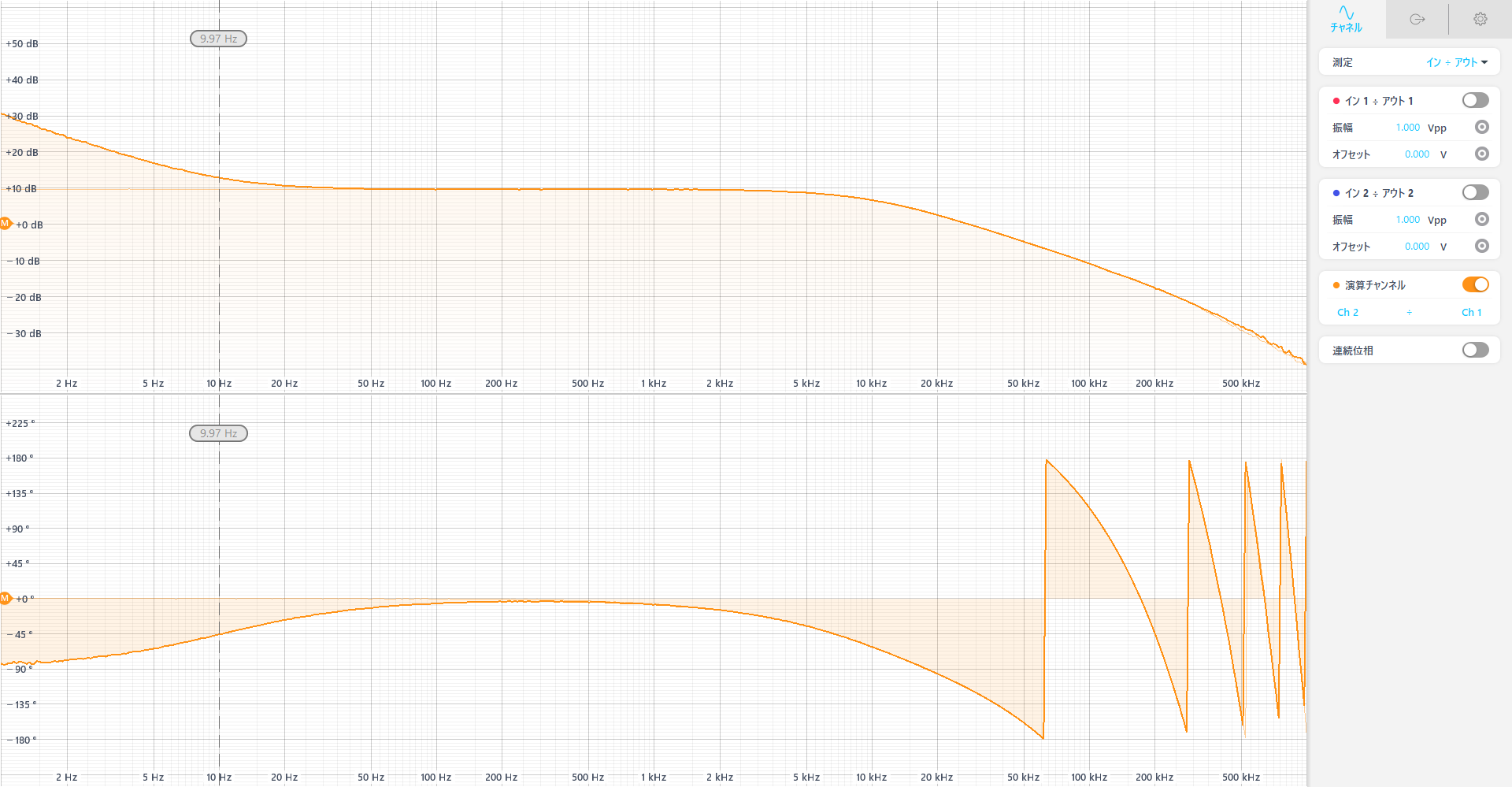
2. Measure TF from IN1 to SLOW_OUT with turning on filters one by one
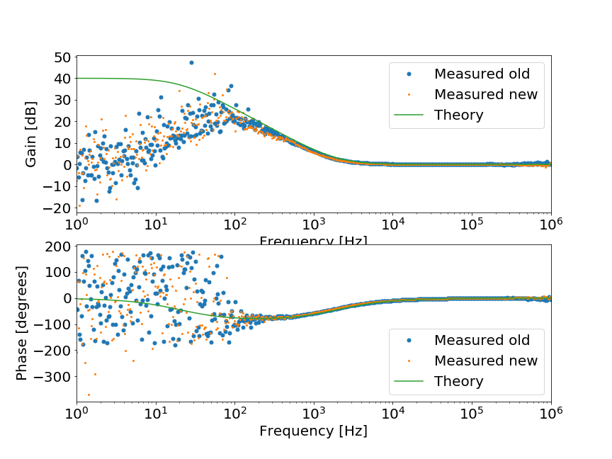
Figure 2-6 show the TF when turning on COMMON COMPENSATION (p:40, z:4k, g:100), COMMON GENERIC (g:1), SLOW BOOST(p:4, z:400, g:100), SLOW COMPENSATION (p:4, g:100), and SLOW GENERIC (g:1)
All TFs seem fine.
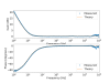
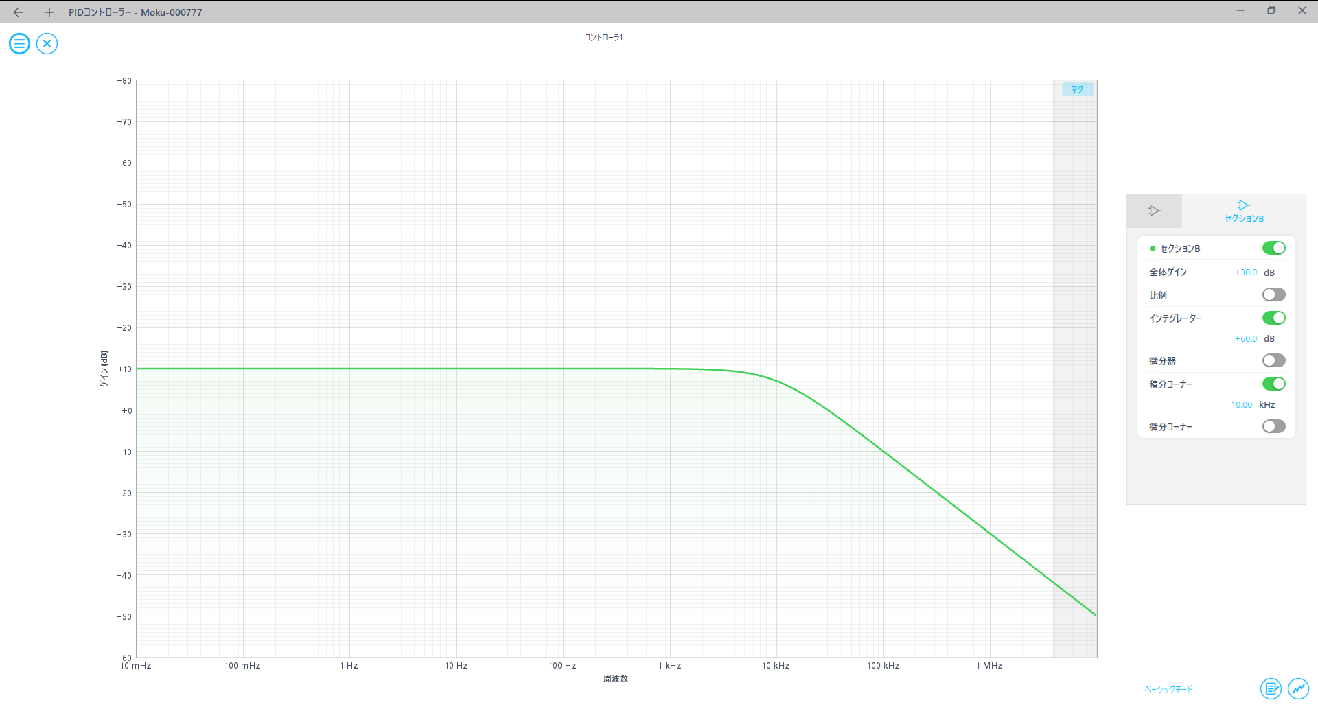
3. Close SLOW loop with Moku:Go
Since SLOW boost filter has integration filter (p:0, z:10), it is difficult to measure the TF of SLOW BOOST 1/2/3 without closing the loop.
So, I made simple low-pass filter (fig7) with Moku:Go and close the CMS loop.
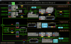
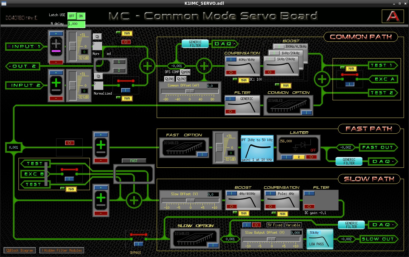
Cablings are just CMS SLOW_OUT -> Moku:Go IN1 and Moku:Go OUT1 -> CMS IN1, and CMS setting is as shown in fig 8.
Figure 9 shows the OLTF of closed CMS loop, which has about 30kHz UGF (ssame as real PLL UGF).
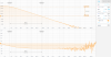
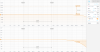
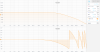
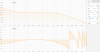
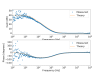
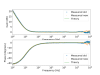
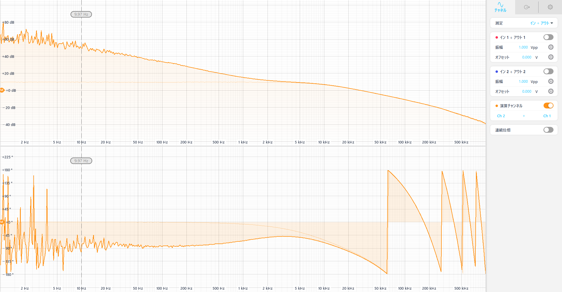
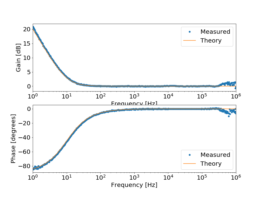
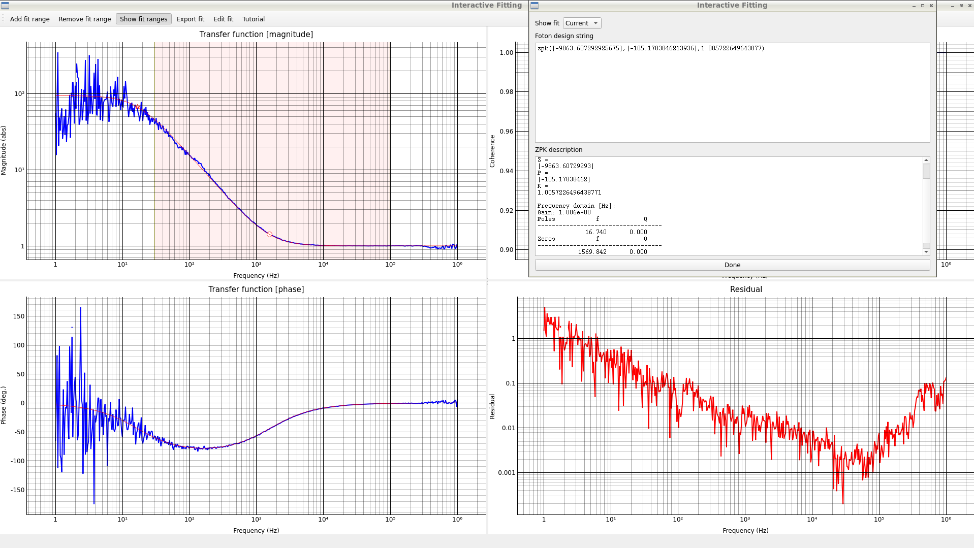
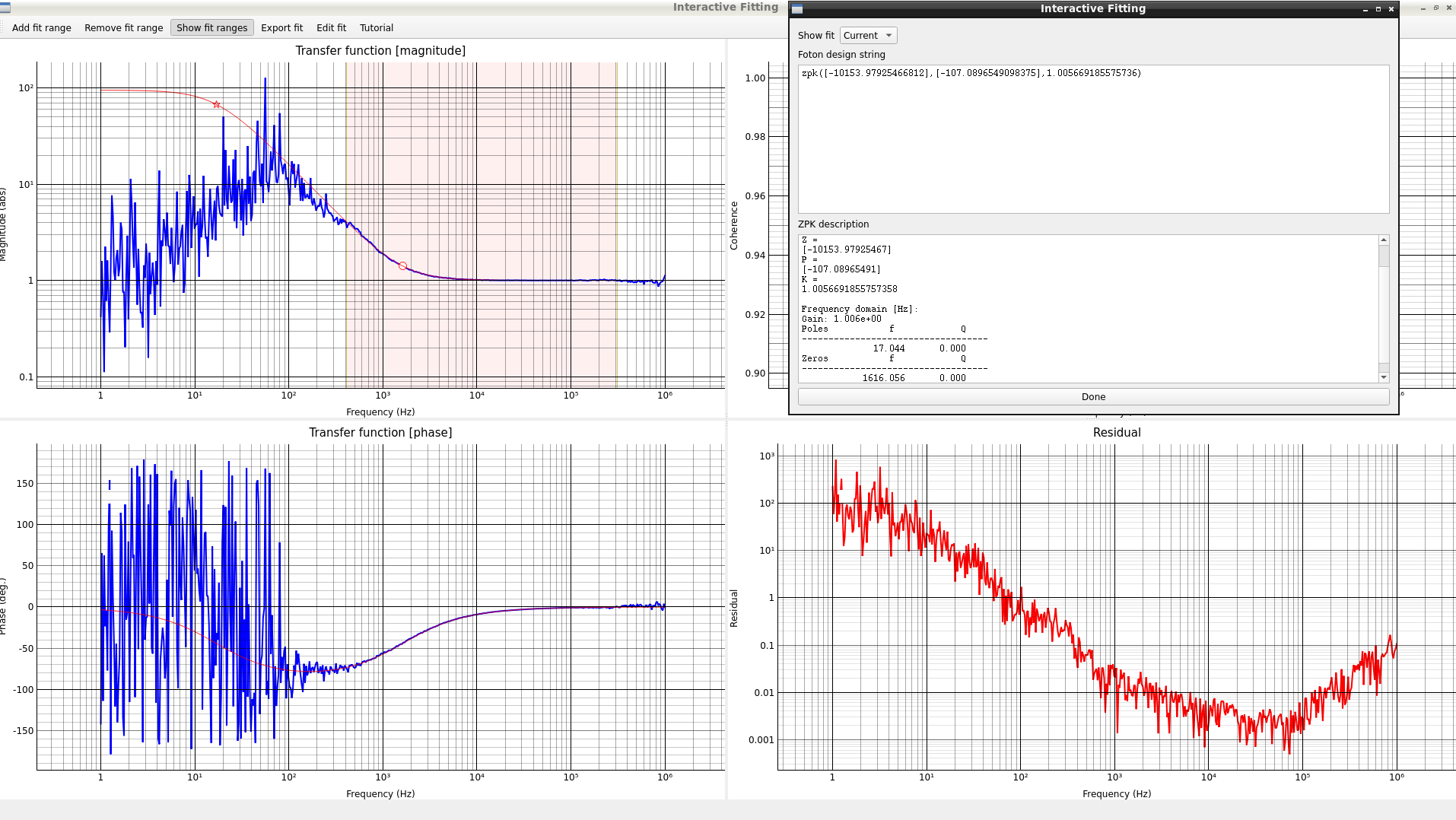
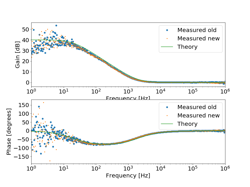
4. Measured OLTF with BOOST 1/2/3 and estimate TF of each filter
Since SLOW BOOST filters cannot turned on one by one, I measured OLTF with BOOST1 (fig10), BOOST 1+2 (fig11), BOOST 1+2+3 (fig12).
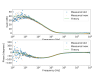
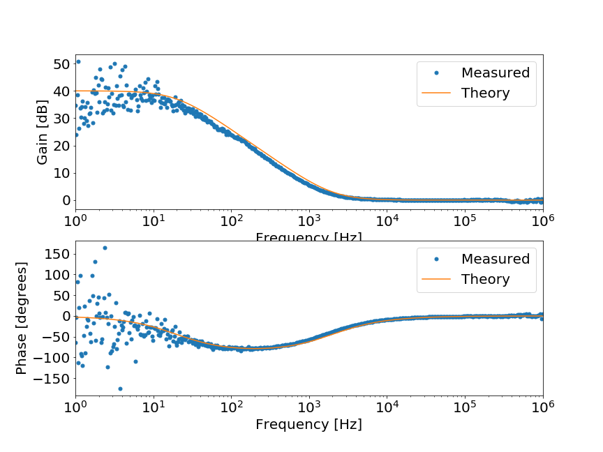
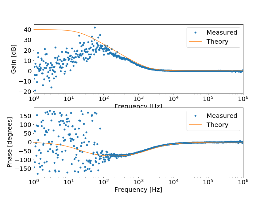
From these TF measurement, I calculated the TF of each boost filter (fig13:BOOST1 (p:0, z:10, g:1), fig14:BOOST2 (p:20, z=2k, g:100), fig15:BOOST3 (p:20, z=2k, g:100)).
Due to the high gain at low frequency, it is difficult to identify pole frequency of BOOST2/3.
In addition, zero frequency of BOOST 2/3 seem to slightly lower than the theory but probably it is acceptanble.
So, spare PLL CMS seems to work well in terms of the TF of each filter.
All measured data and plot are uploaded in JGWdoc (S2415893).


