Continuted from klog30722.
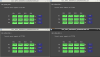
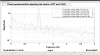
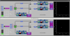
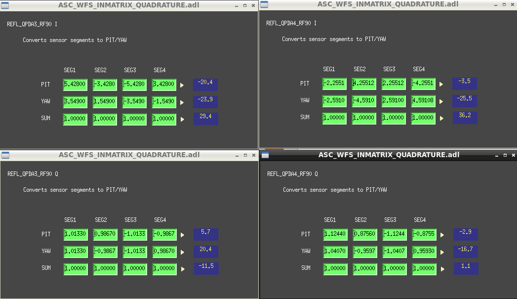
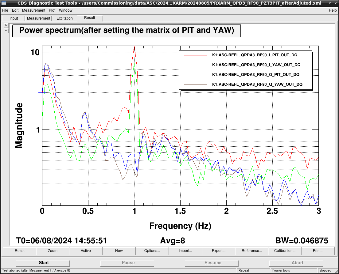
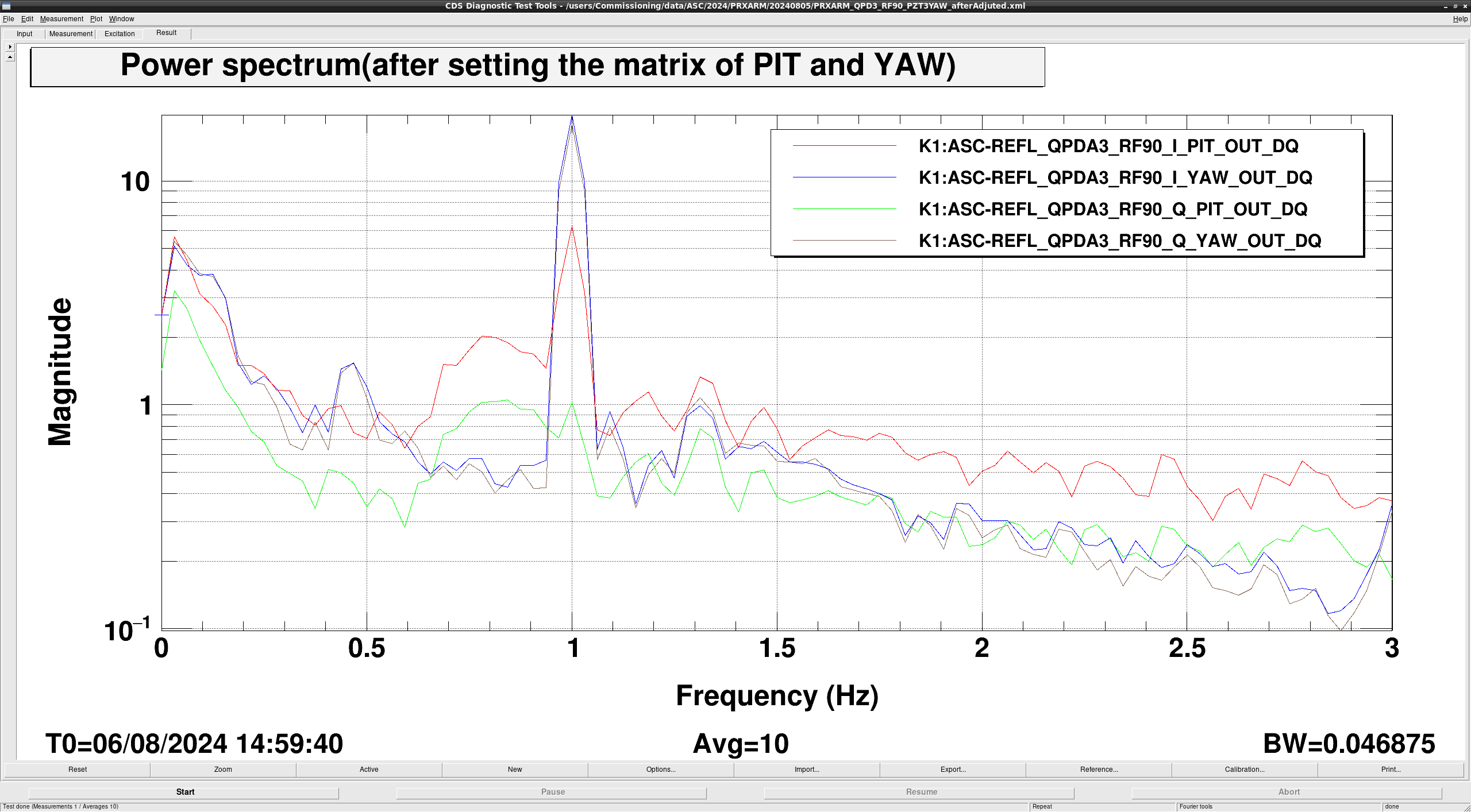
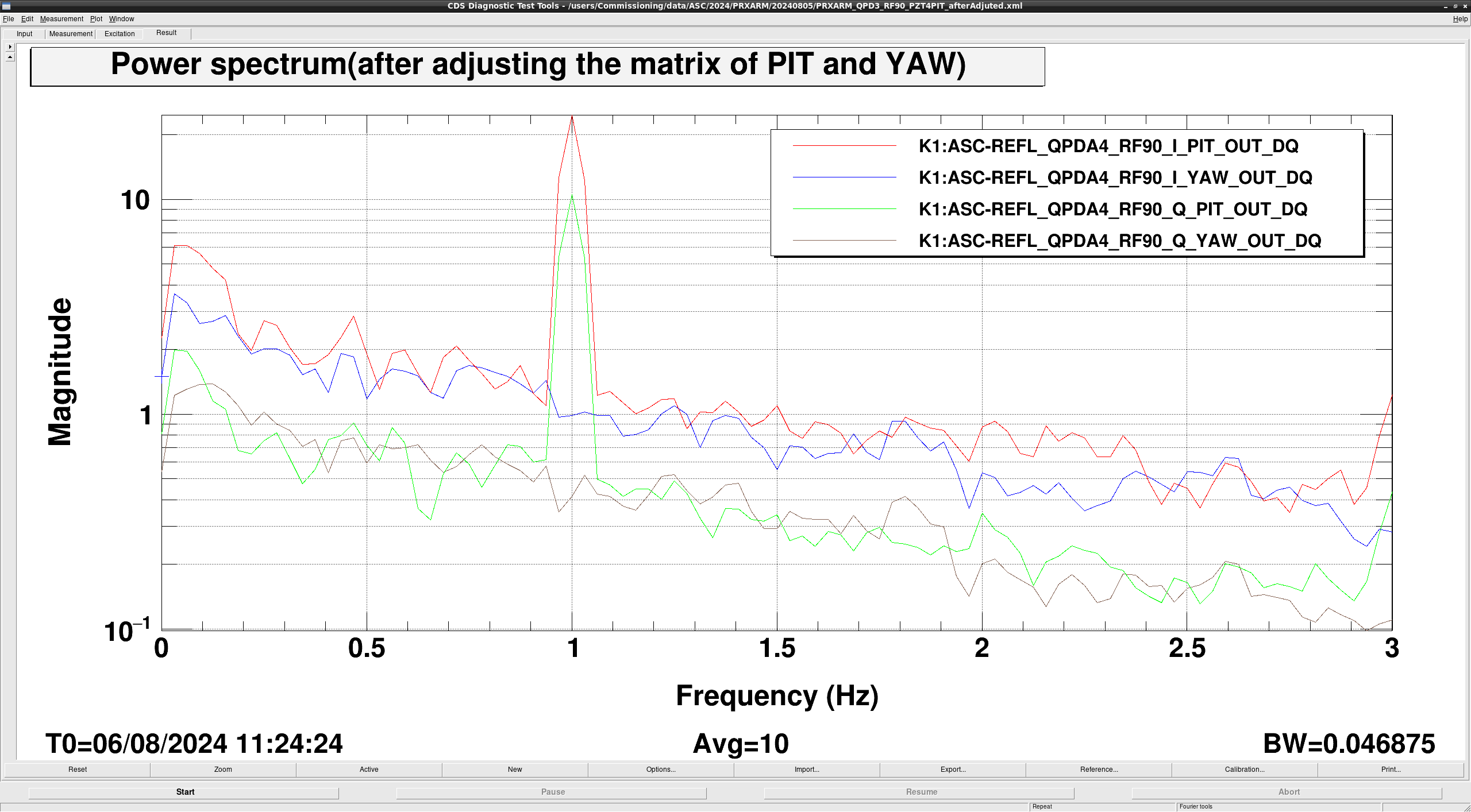
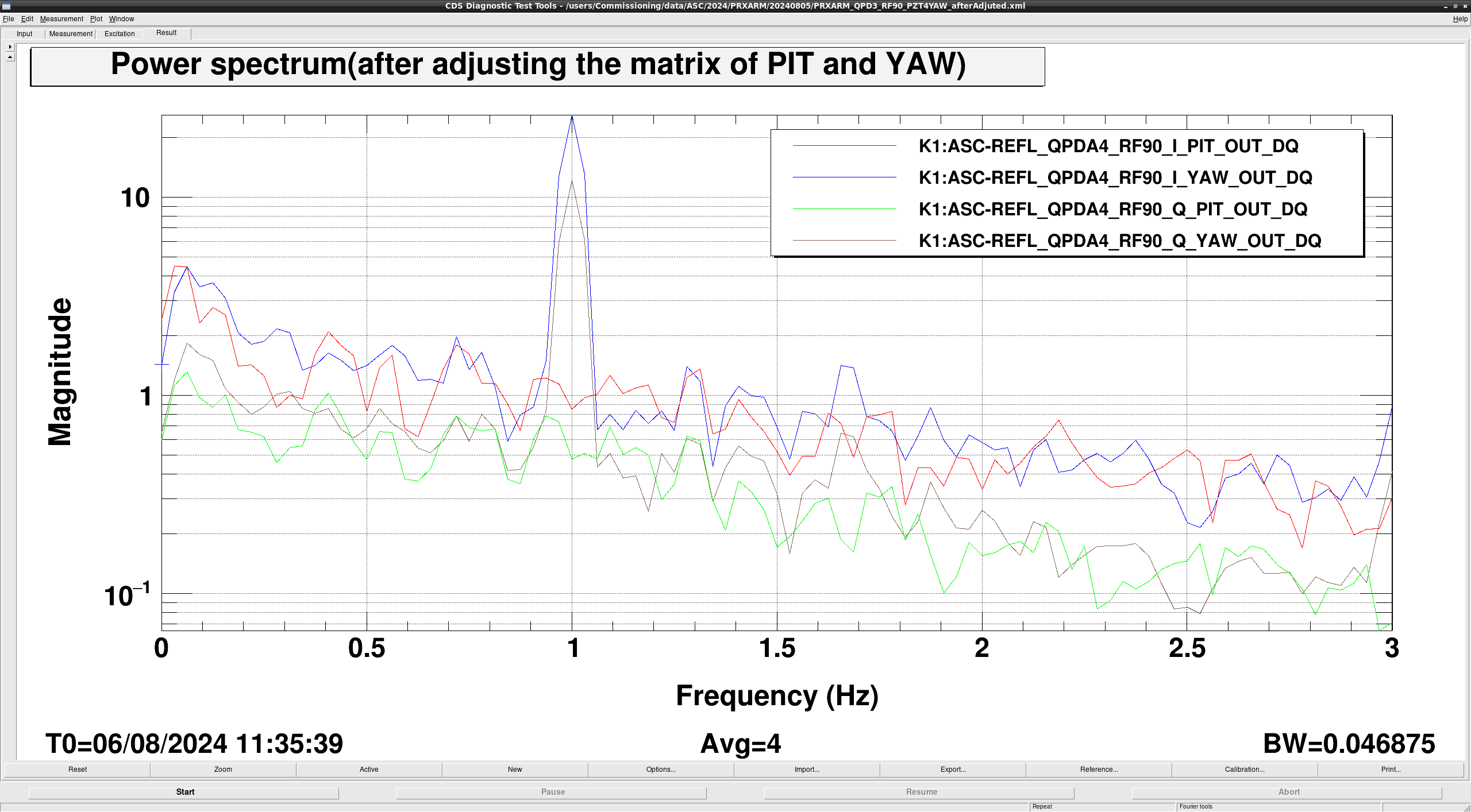
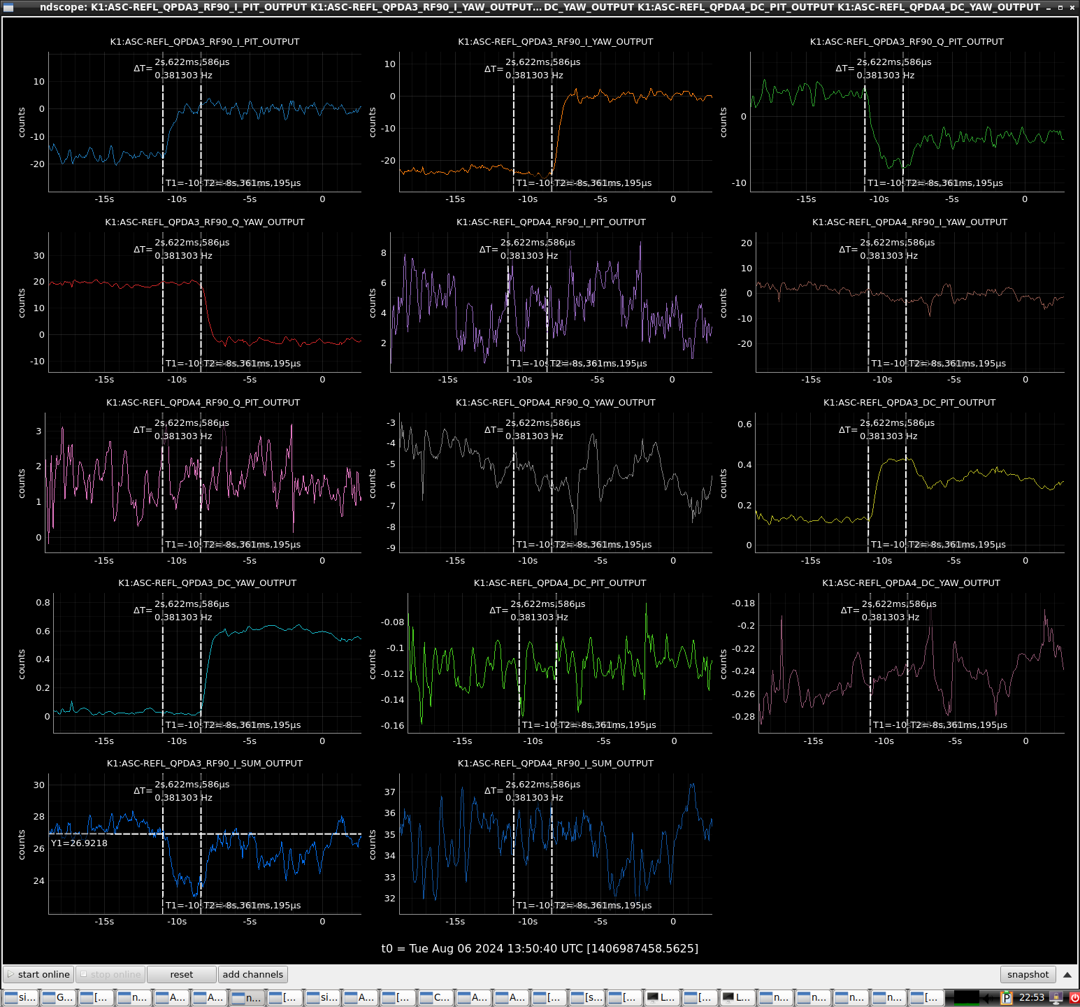
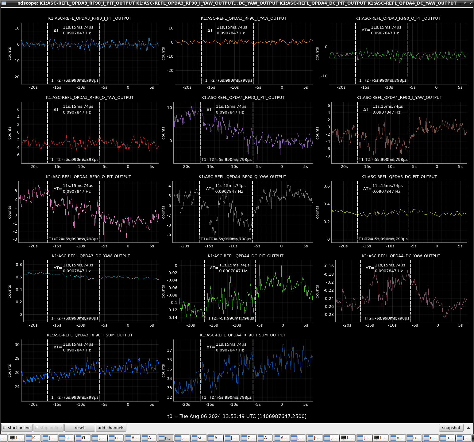
I set the PITYAW coupling correction value to the I and Q matrix of QPDA3,4 of REFL's RF90 (FIG1). When I waved PZT3 and 4 to PITYAW, I saw each signal. (FIG2: PZT3_PIT, FIG3: PZT3_YAW, FIG4: PZT4_PIT, FIG5: PZT4_YAW)
Also, with this matrix included, I calculated the demodulation phase using the I and Q signals, and turned the phase for each segment so that the Q signal disappeared, but the Q signal did not disappear. On the contrary, PITYAW coupling was created again. Originally, I should have adjusted the demodulation phase of I and Q before the matrix, but for now, since the PIT and YAW signals are visible in the I phase, I would like to proceed without adjusting the demodulation phase.
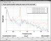
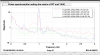
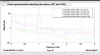
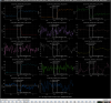
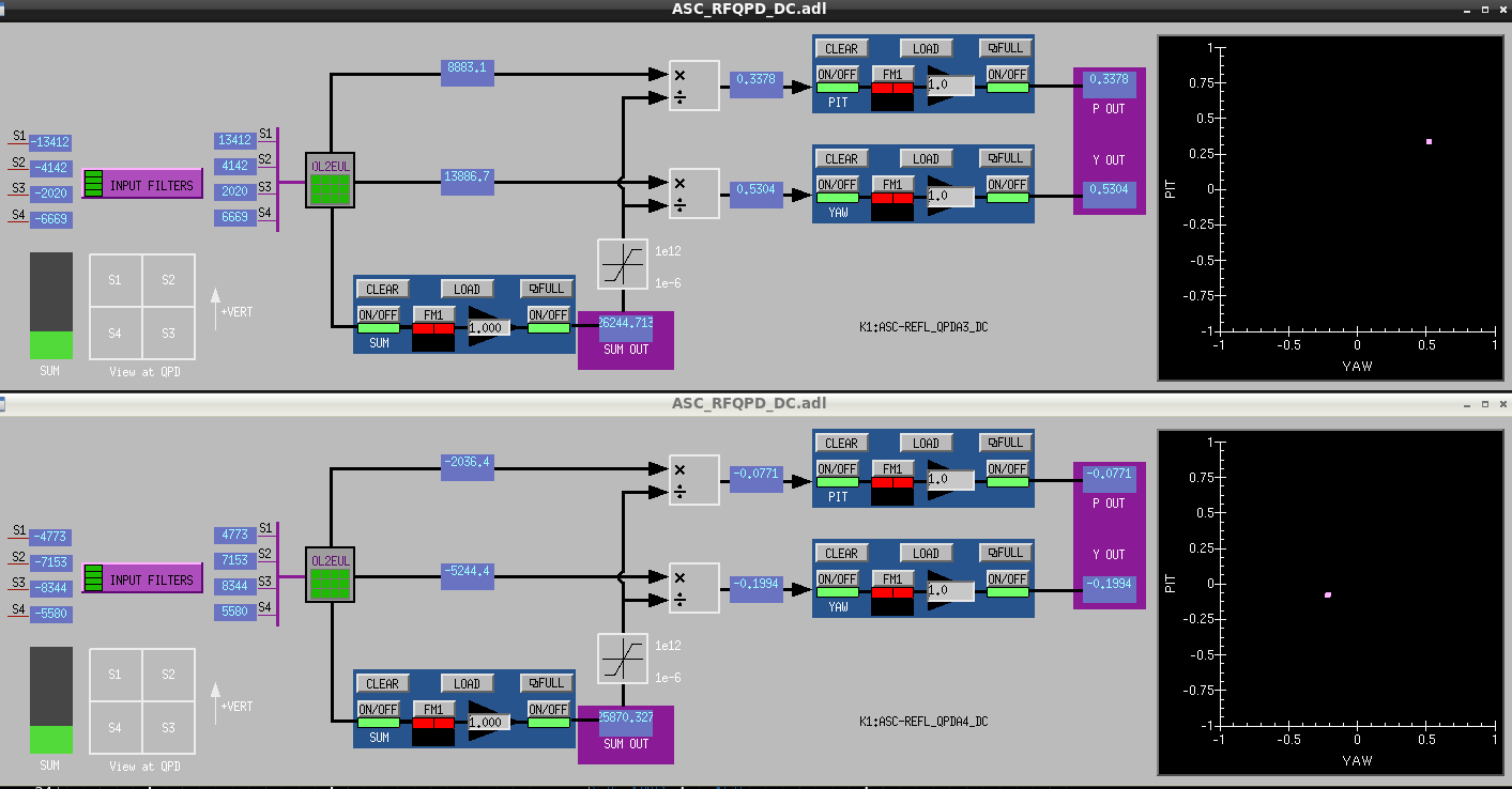
I also tried to install an RF90 DC centering loop on DC1 and DC2 using only I demodulated signal of QPDA3 and QPDA4. The RF90 error signal was fed back to make it zero. However, the DC beam spot was quite off-center. (FIG6) Also, when I observed at the RF90_I_SUM_OUTPUT, it seemed to be slightly lower.(FIG7: The first x-axis is when the QPD 3 PIT is turned on, the next x-axis is when the QPD 3 YAW is turned on., FIG8: The first x-axis is when the QPD4 PIT is turned on, the next x-axis is when the QPD4 YAW is turned on.) I found it very difficult to evaluate the DC centering loop with RF90.
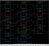
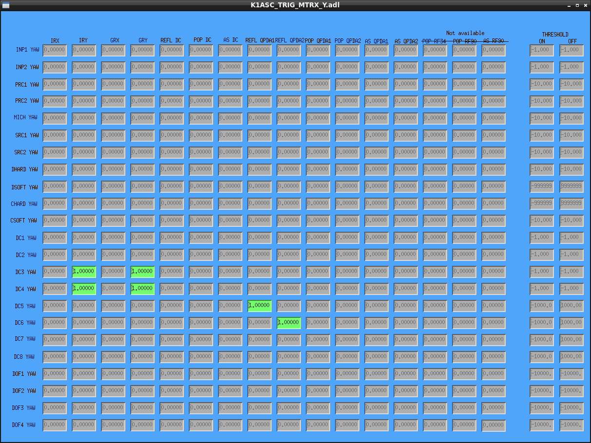
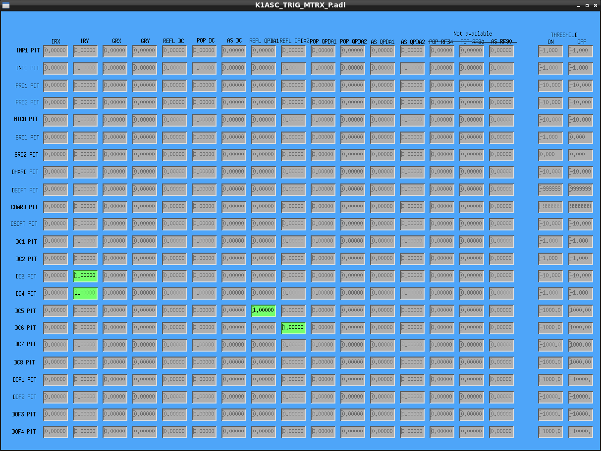
Also, thresholds were set for the DC1 and DC2 error signals. I set these to -1.0.(FIG9: YAW,FIG10: PIT)