[kTanaka, Hirose]
We locked PRXARM for PRXARM ASC work and adjusted PITYAW coupling of RF90 WFS signal as one of the preparing work for PRXARM ASC(WFSf3).
What happened before locked PRXARM
- The FIB error RMS signal was as high as 250, so when the WOOFER gain was turned on, the error signal threshold was exceeded in the "@fib_lock_check" in the ALS_FIBX guardian and the lock went down. We changed the threshold to 300 on the ALS-FIBX Guardian to lock it.
- Xarm did not lock at first during the initial alignment, but I forgot to change the HWP of the REFL from 176 to 146.176 is the HWP value for PRXARM. I noticed that the HWP value was not specified when locking with the Xarm guardian. If the HWP is 176, XARM can lock, but when the COMMON_CMS boost is applied, the transmission power drops from 1.0 to 0.8, and the Xarm lock went down over time. When I returned the HWP parameter, that behavior disappeared, so appropriate reflection power is required.
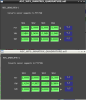
- When I inserted the Xarm ADS, the PR2 YAW was fluctuating the TRANS, so I lowered the gain to 0.3.(FIG1)
- Before performing the ASC work on PRXARM, I performed PRXARMADS. As an ITMXETMX actuator, it needs to be returned to the OPLEV setpoint, but it was returning to the TM LOCK filter.In that state, the maximum XARM transformer power of PRXARM was about 3.2. After we finished the ASC work, Tanaka-san noticed this and re-performed the ADS. The XARM transformer power of PRXARM was gone about 3.7. I need to put a process into the Guardian to switch actuators.
PRXARM ASC WFSf3 work
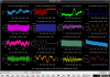
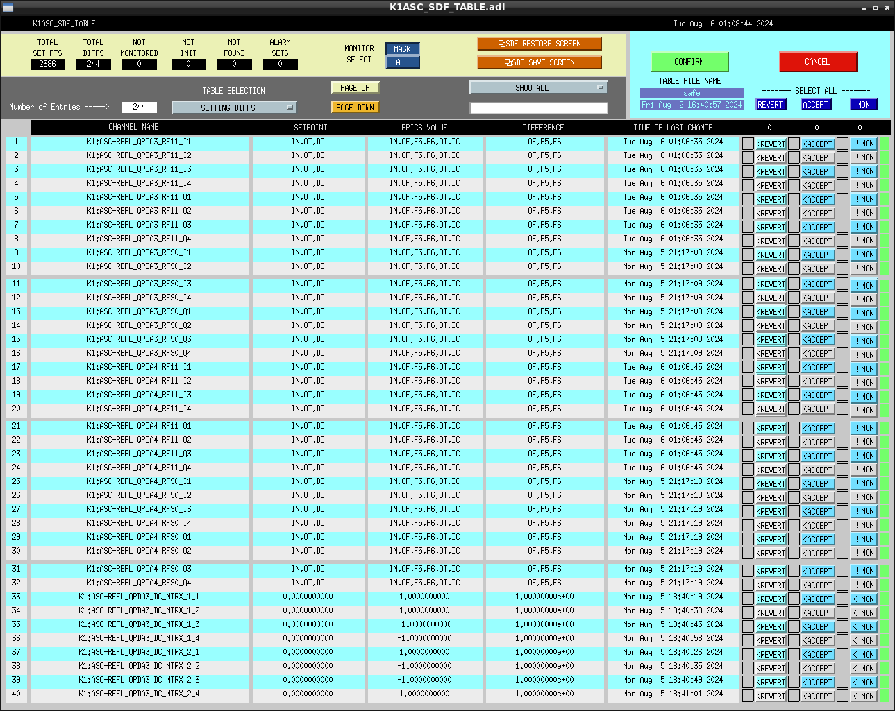
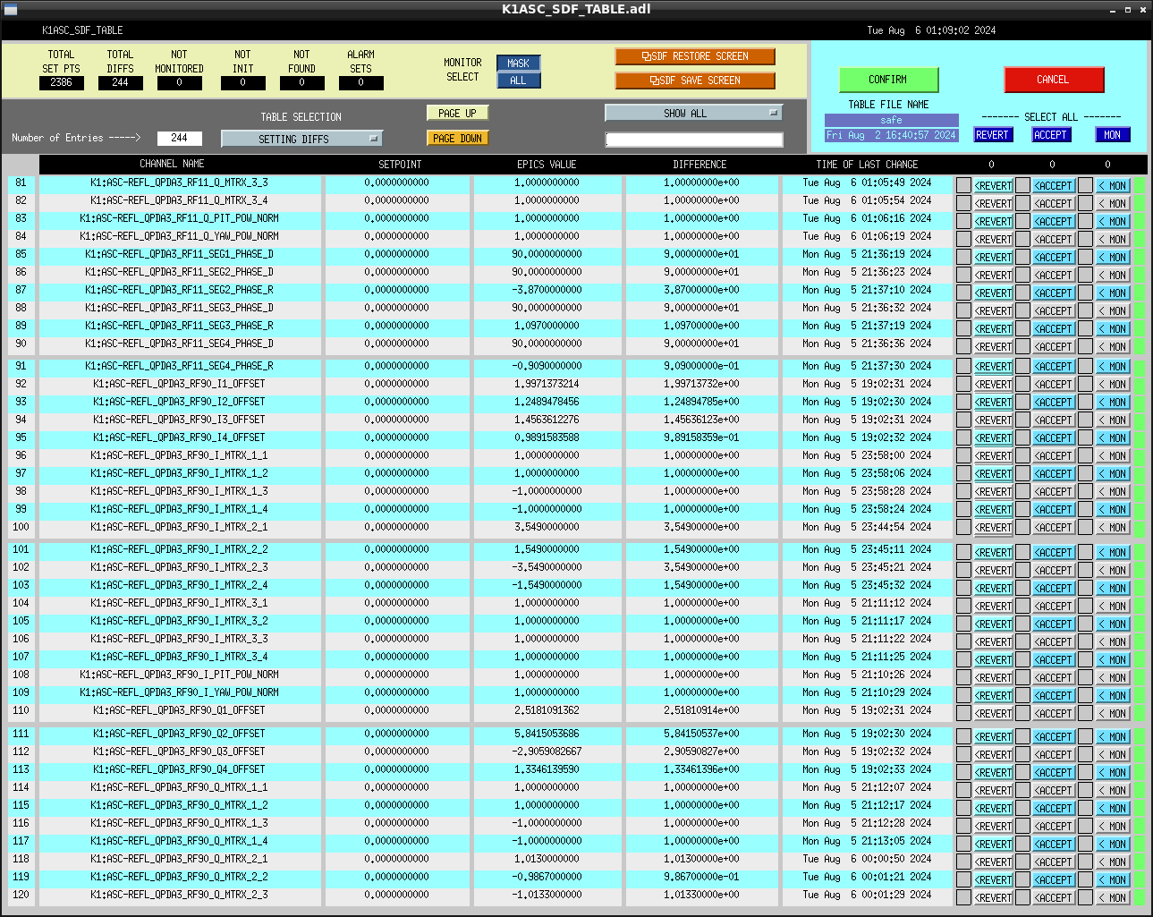
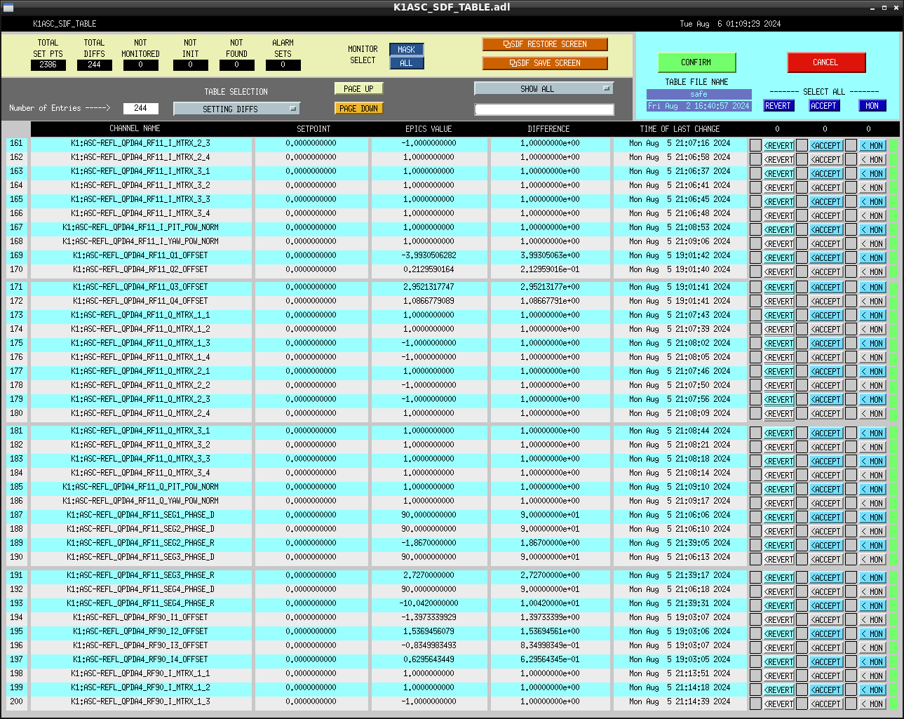
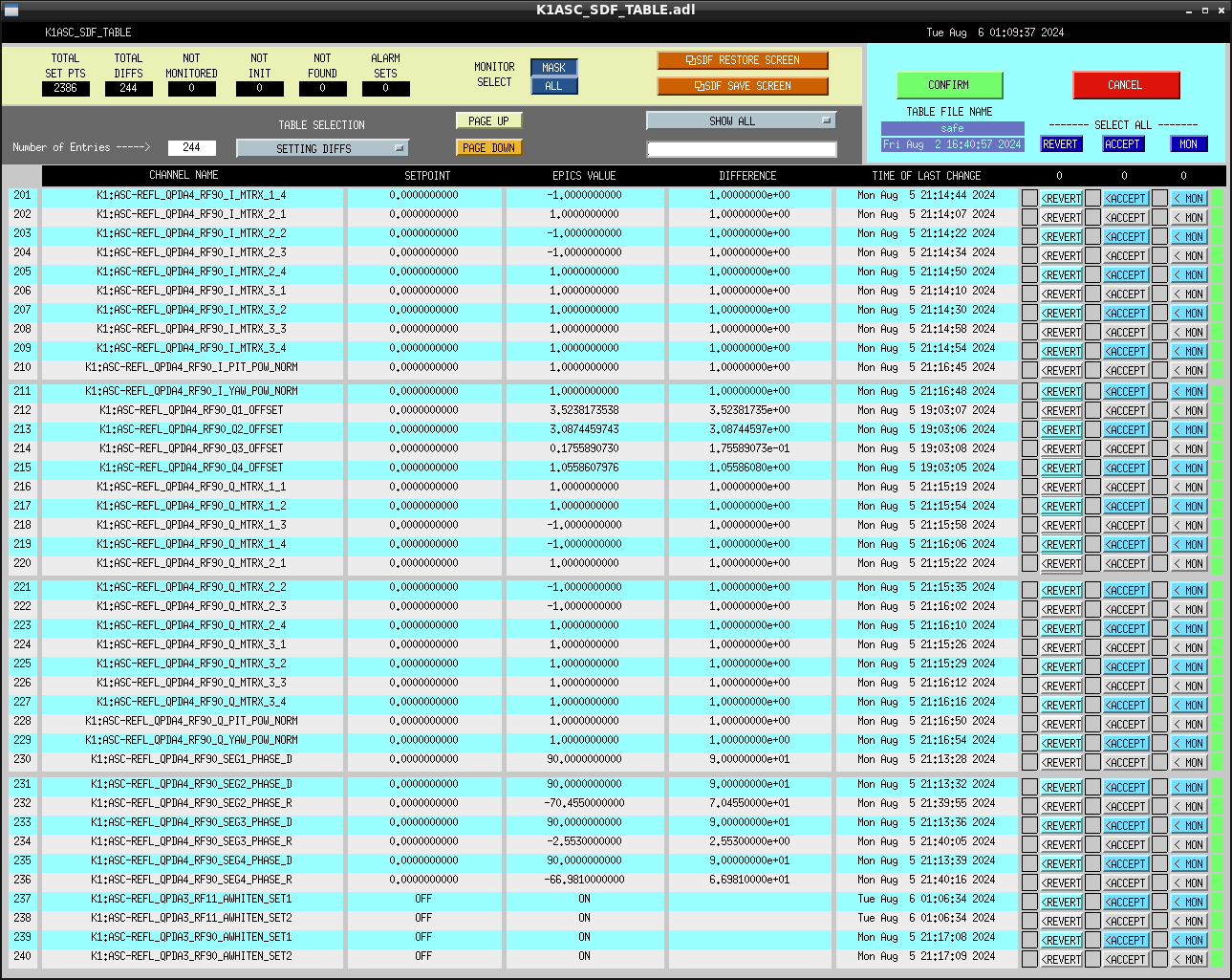
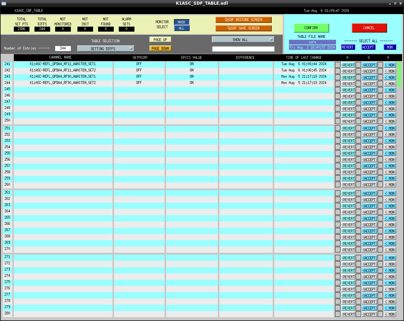
- On the maintenance day, the parameters related to QPD3 and 4 of WFSf3 were reset, so I restored them. I thought I had accepted the parameter changes in the SDF of the digital system, but for some reason they were reset. This time, I accepted the following in safe mode.(FIG2-FIG8)
- I also created a python file for the channel for WFSf3 based on Dark Offset Code. (/opt/rtcds/userapps/trunk/asc/k1/scripts/zeroWFSoffsets_REFLf3.py)
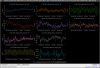
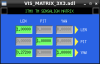
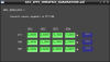
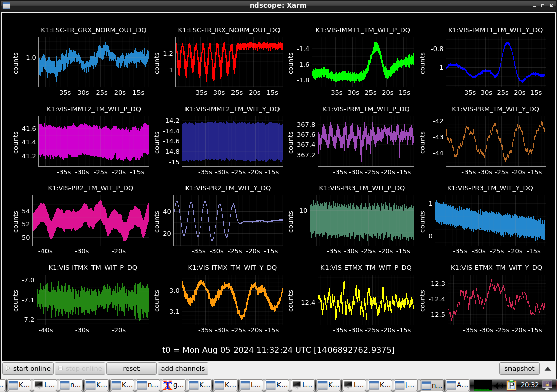
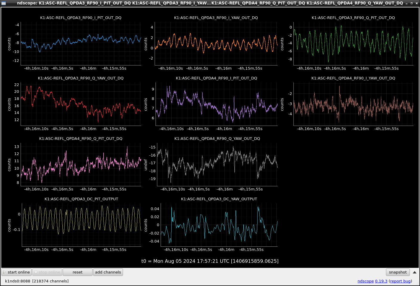
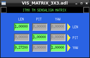
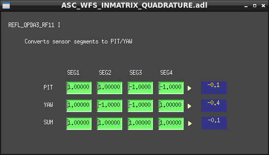
However, since looking at all the test point channels could potentially put a large load on the system, I rewrote QPD{3,4}_RF{11,90} one by one in the file. - We will prepare to investigate how much signal detection WFSf3 can perform. First, we will install a DC centering loop in RF90. When excited the PZT3 PIT as the actuator, I checked whether there was PITYAW coupling. On DC, only the PIT signal was visible. However, the PIT excited signal was visible on the YAW of QPD3_RF90(FIG9). It is necessary to correct the PITYAW coupling in the digital system of RF90. However, in WFS's RF90 detection, there are not a mechanism like OPLEV's SENSALIGN_MATRIX (FIG10), and we must enter a value to cancel PITYAW coupling in the matrix(FIG11) for each segment.
The calculation is as follows:
PIT_segment_list=[1,1,-1,-1]# the initial values of SEG1, SEG2, SEG3, SEG4Yaw_segment_list=[1,-1,-1,1]# the initial values of SEG1, SEG2, SEG3, SEG4
Values to be set in the segment matrix of the YAW.:PIT_segment_list*(YAWsignal/PITsignal)+YAW_segment_list
Also, the YAWsignal/PITsignal are as follows when the QPD3_RF90_{I,Q} segments are at their initial values.
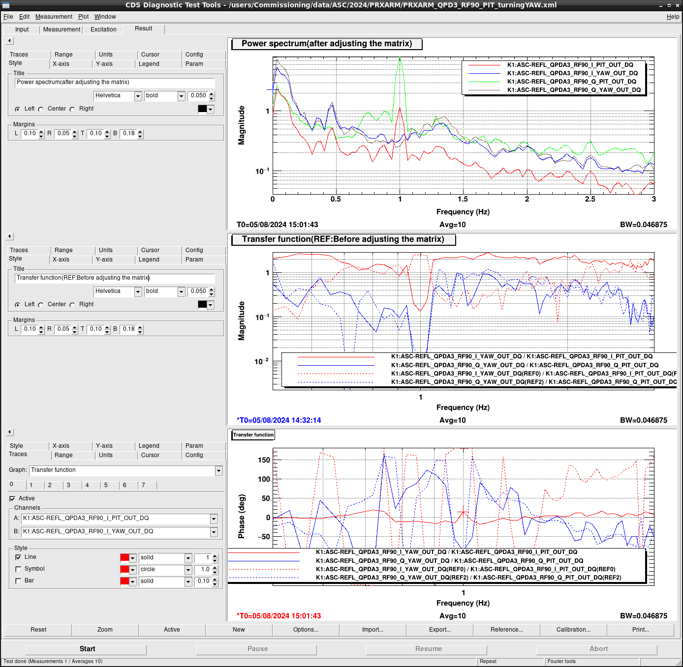
The values adjusted on QPD3_RF90_{I,Q}: FIG12, Diaggui:FIG13 -
YAWsignal/PITsignal QPD3_RF90_I 2.549
QPD3_RF90_Q 0.0133
Future plan:
- Continuing to adjust the PITYAW coupling.
- Installing DC centering loop.
- Implementing PRXARM ADS to Guardian for actuator switching.


