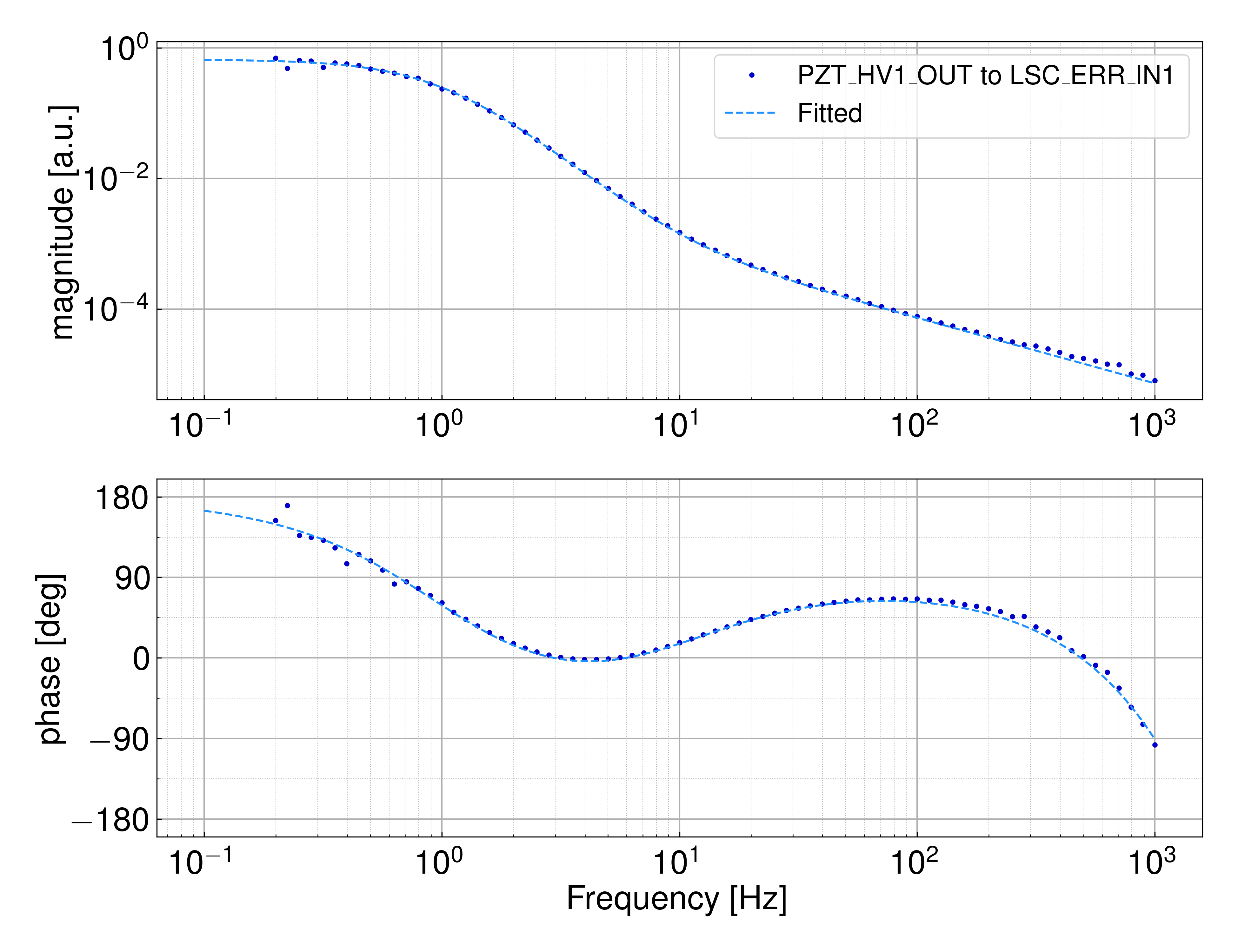
I fitted the transfer function from K1:OMC-PZT_HV1_OUT to K1:OMC-LSC_ERR1. The fitted function is written as:
where fc, G, and t0 are the fitted parameter. fc corresponds to the pole of the RC lowpass filter, G is the overall gain and t0 means the time delay. The third term in the fitted function is the dewhitening filter.
The rerult is shown in Figure1. I got the fitted parameters as follows:
fc: 1.09(2) Hz, G: -0.663(5) cnt/cnt, t0: 500(6) µs
Using the overall gain, G, we can estimete the calibration factor of the error signal by combining the actuator efficiency previously estimated in this post, 1.3(1) e-10 [m/cnt]. Finally the calibration factor estimated by this method is 5.1(4) e9 [m/cnt].
By the way, it seems that the actual pole of RC filter is much different of the model in FM10 of OMC-LSC_FB_FLT. In this model (and our first guess), the pole is calculated by a resister of 50 kΩ (R151 in the circuit diagram) and a capacitor of 470 nF (C126). It seems that we forgot to inculde a capacitor of 470 nF (C111) and the capacitance of the piezo actuator itself (Noliac NAC2124-H08, 1380 nF). If we take all of these capacitance into consideration, the total capacitance is 2320 nF and the corresponding pole is 1.37 Hz, which is still higher than the fitted value but much better estimation than the previous one, 6.7 Hz.