Reports 1-1 of 1 Clear search Modify search
MIF (General)
satoru.takano - 19:22 Saturday 20 July 2024 (30490) Print this report
OMC Commissioning Day4: Calibration of error signal

Aso (remote), Komori (remote), Takano

Abstract

Calibration of the error signal of OMC length control is ongoing. First the actuator efficiency was calibrated, and we got almost the same value as this report. Next step is to calibrate the error signal from the transfer function measurement from the actuator input to the error signal.

Detail

To discuss the effect of the vibration to the fluctuation of OMC length quantitatively, we started to calibrate the error signal of OMC length.

We came up two strategies:

Aso method

  1. Calibrate the actuator efficiency of the piezo [m/cnt] by scanning the cavity length and measuring the counts which is necessary to change the length by 1 FSR of the cavity.
  2. Add an offset to the input (K1:OMC-LSC_ERR_OFFSET) to detune the cavity.
  3. Check the change of the actuator input (K1:OMC-PZT_HV1_OUT). With the actuator efficiency we estimated above, we know how much the actuator moves.
  4. Check the change of the error signal (K1:OMC-LSC_ERR_IN1). It should be a value that is the same as the offset we added with an opposite sign.
  5. Comparing the values obtained in 3 and 4, we get the calibration factor of the error signal [m/cnt]

Komori method

  1. Calibrate the actuator efficiency of the piezo [m/cnt] by scanning the cavity length and measuring the counts which is necessary to change the length by 1 FSR of the cavity (same as the previous one).
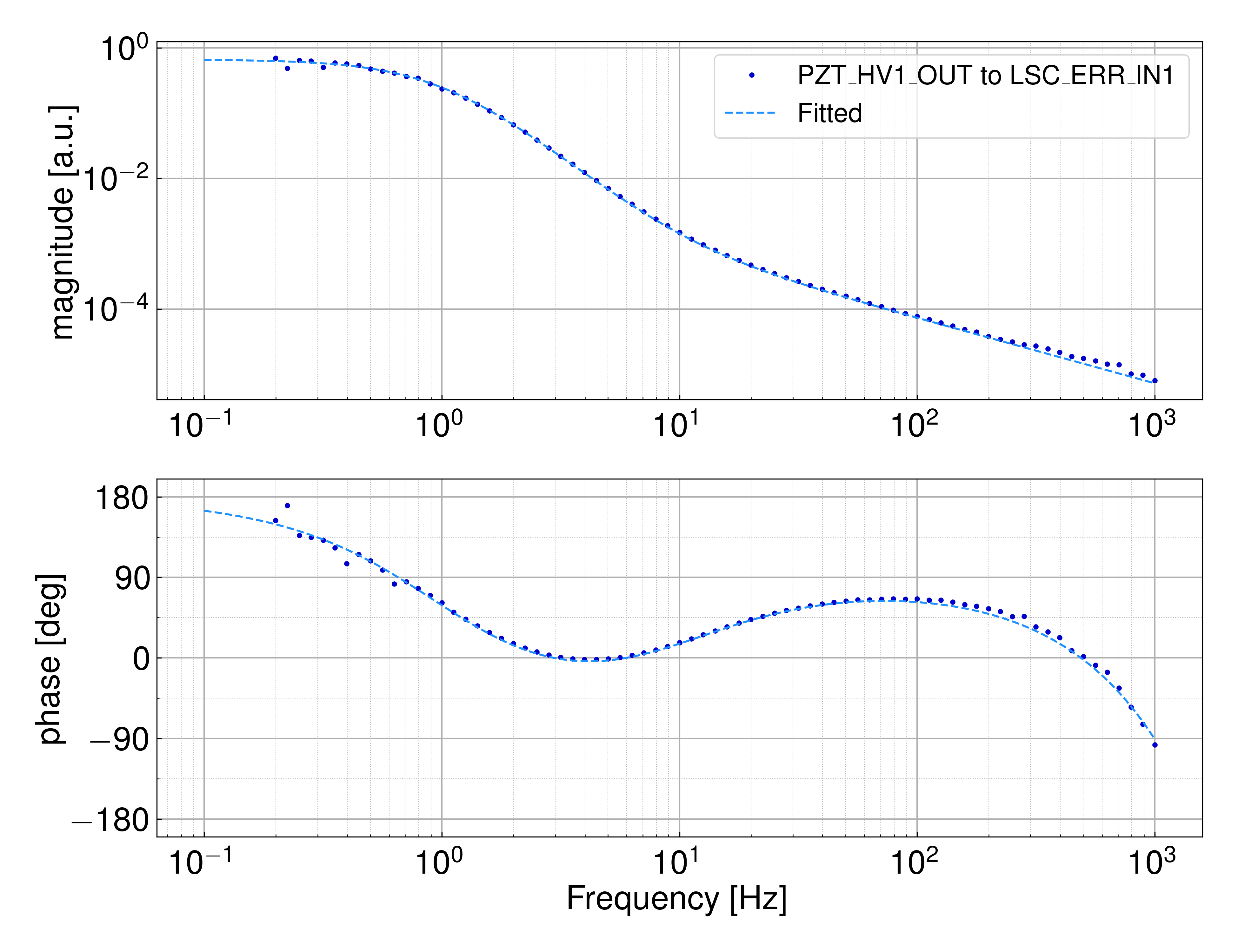
  2. Inject an excitation to the actuator input (K1:OMC-PZT_HV1_EXC) and measure the transfer function to the error signal (K1:OMC-LSC_ERR_IN1).
  3. The transfer function is given by​​​​​​

H = \frac{SA}{1+SAF}, where A [m/cnt] is the actuator efficiency, S [m/cnt] is the calibration factor, and F [cnt/cnt] is the feedback filter. We already know F and A, then we get S.


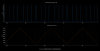
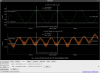
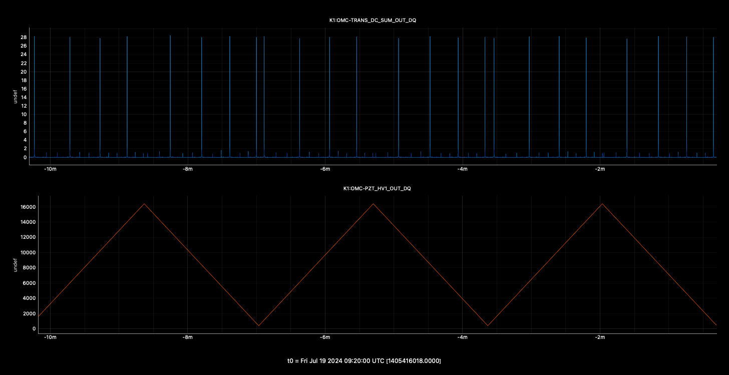
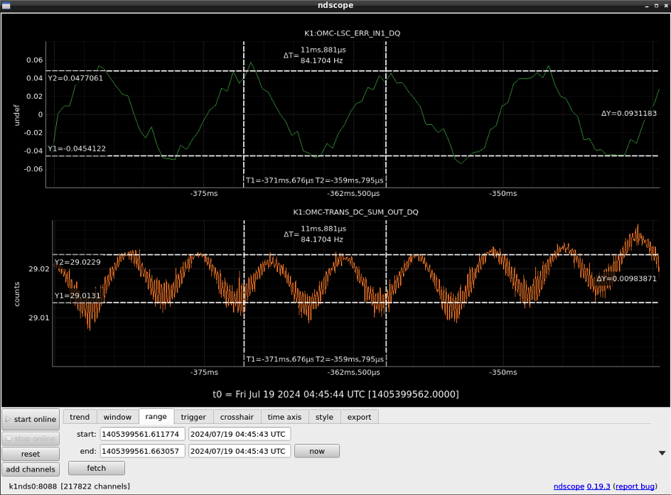
First of all, I measured the actuator efficiency by scanning the cavity. Figure1 shows the timeseries of the scan. The distance between the peaks are not the same, because of the nonlinearity and the hysterisis of the piezo actuator. To avoid these effects, I picked up the peaks at which the actuator input is avobe 3000 cnt. Finally, we get the actuator efficiency of 1.3(1)e-10 [m/cnt], which is consistent with the previous measurement.

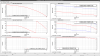
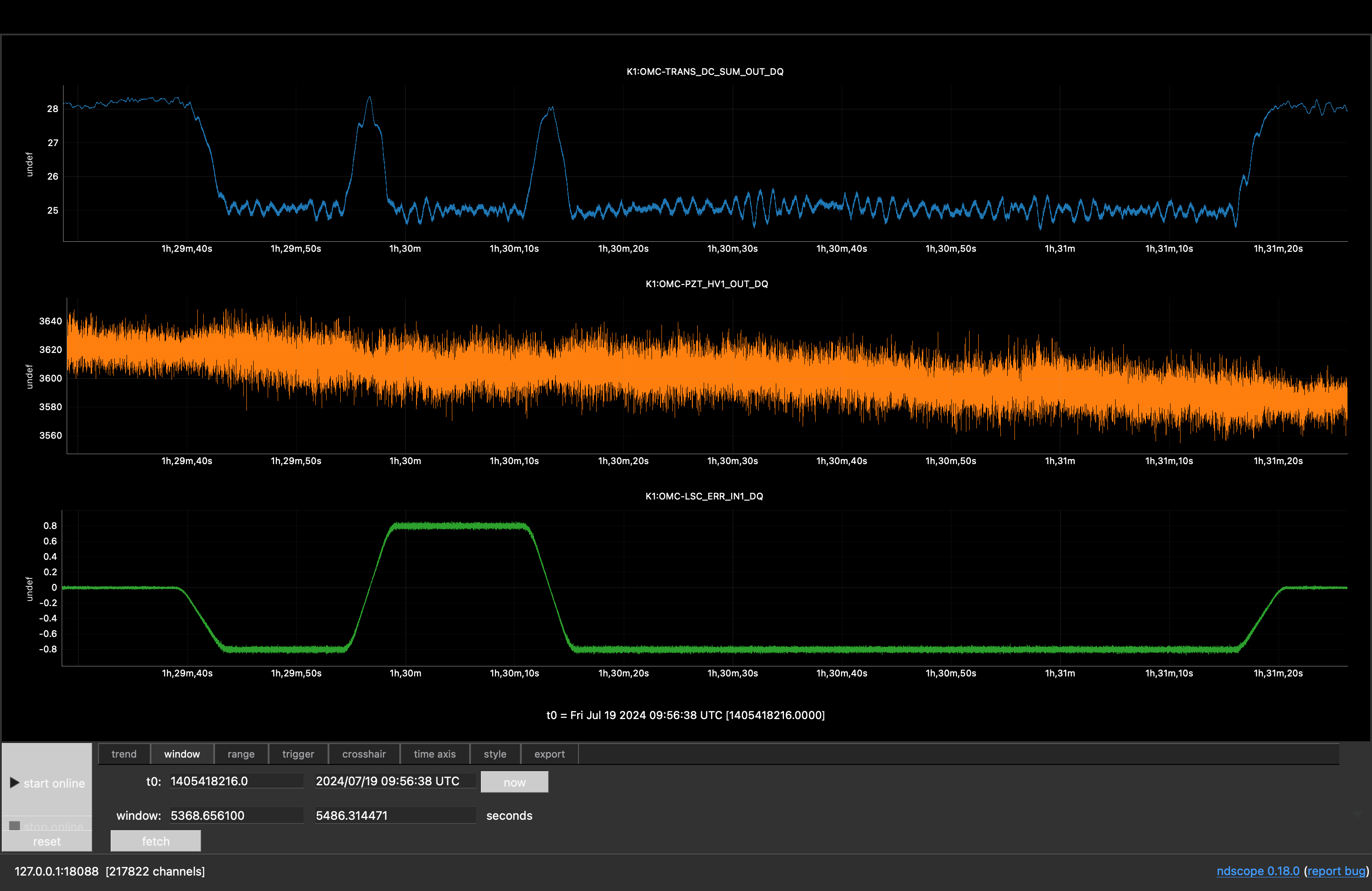
Next, I tried adding offsets and checking the shift of the error and the feedback signal. Figure2 shows the timeseries when I changed the offset of the error signal. It seems that the shift of the feedback signal is buried with the background fluctuation. I could not add larger offset because the cavity lock was lost, so I gave up this method.

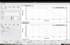
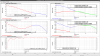
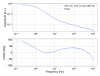
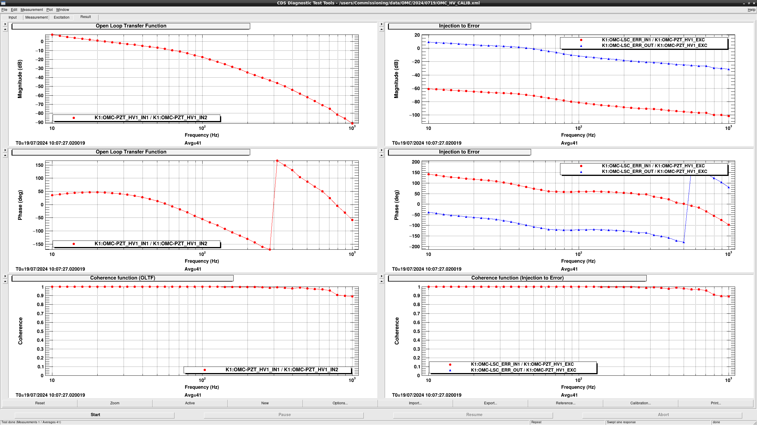
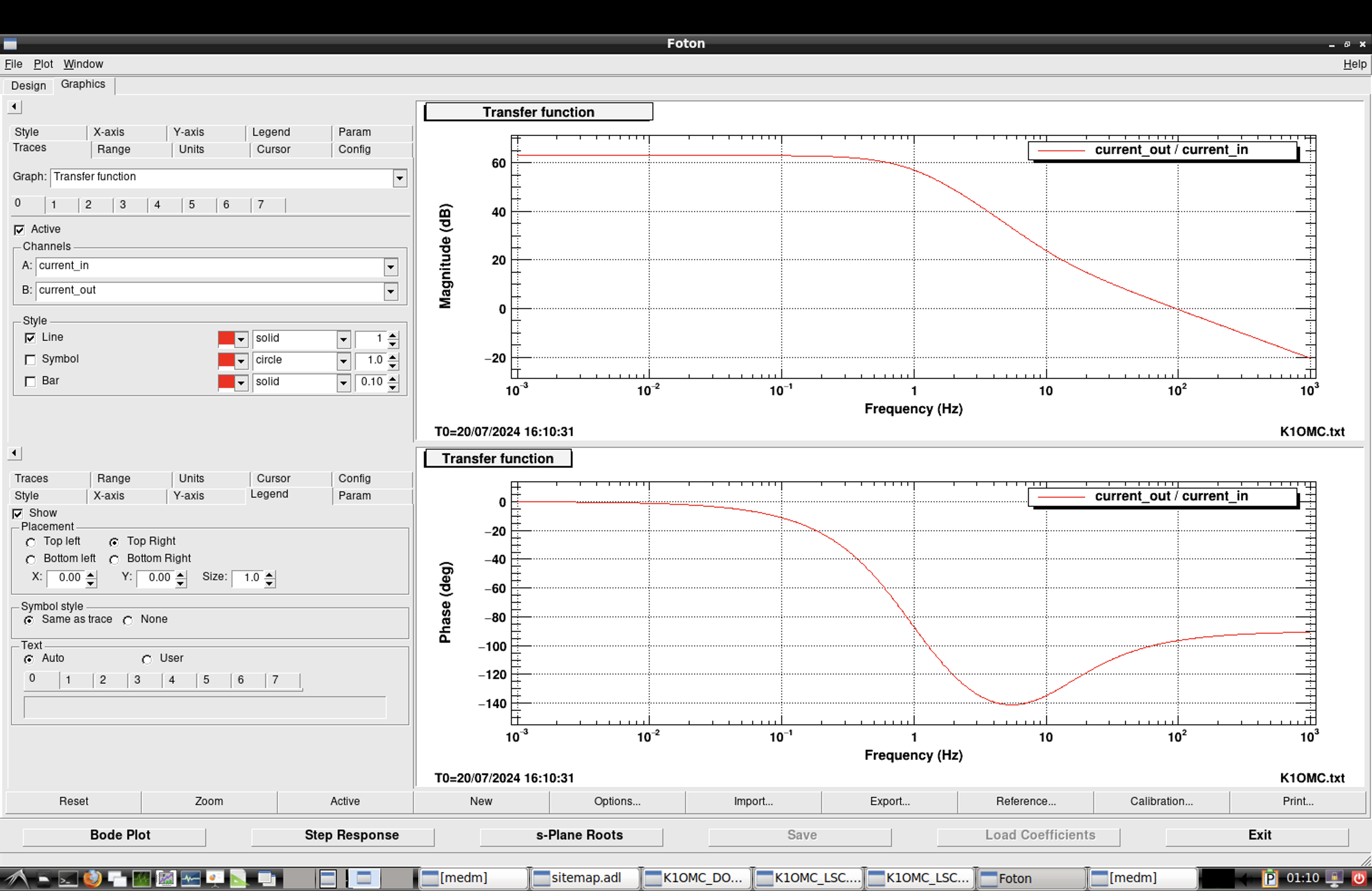
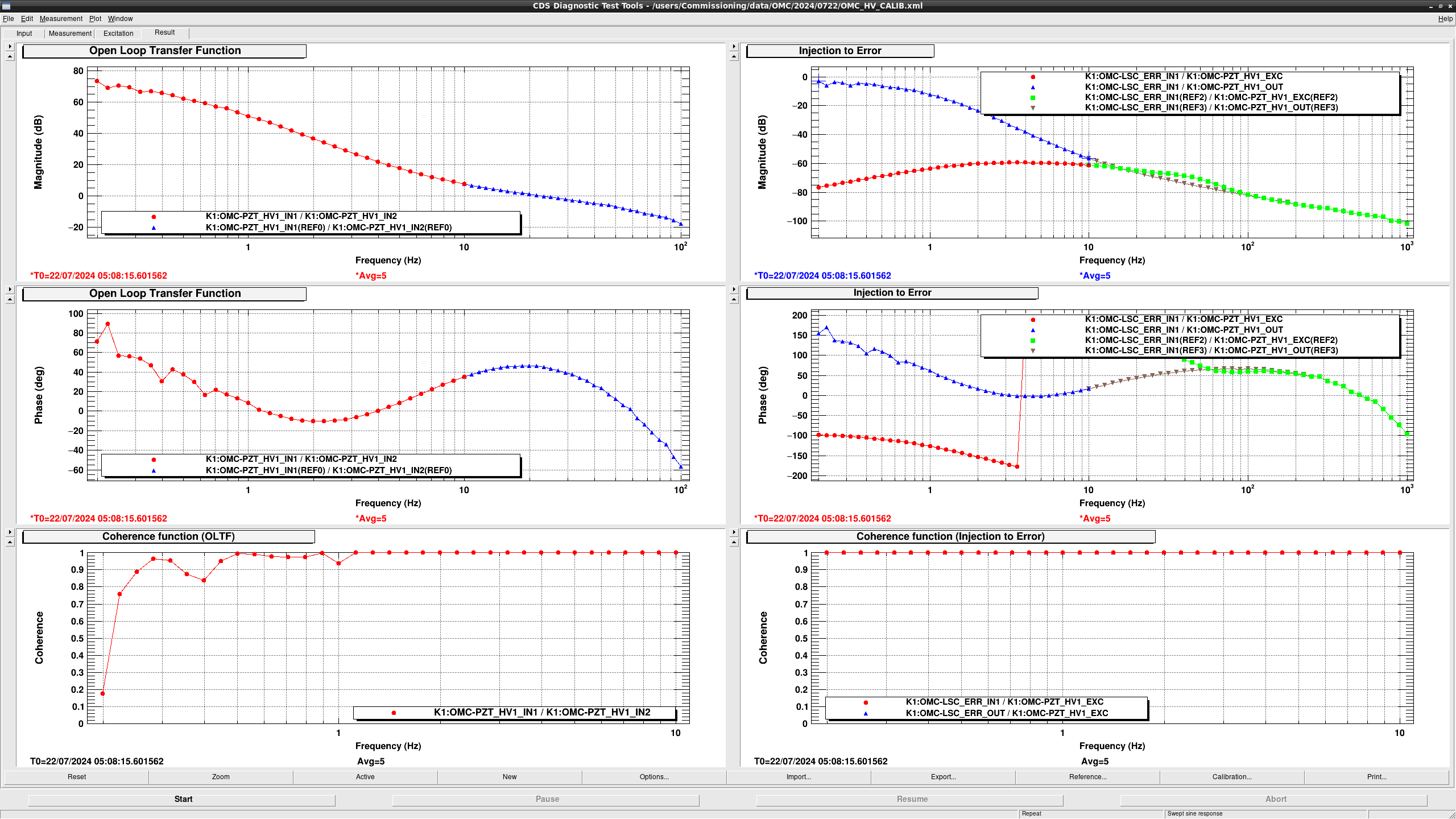
I moved on to the Komori method. I injected an excitation to K1:OMC-PZT_HV1_EXC and measured the transfer functions between many channels. Figure3 shows the measured results. The plots in the left column are the open loop transfer function. In the current control setup UGF is around 20 Hz. The plots in the right column are the transfer functions from the excitation signal (K1:OMC-PZT_HV1_EXC) to the error signal (K1:OMC-LSC_ERR_IN1/OUT). Above UGF, they should be approximated to AS, and from the measurement it seems to have some frequency dependency. Considering the circuit diagram of the piezo driver (here), there is a pole at 6.4 Hz in the driver and this can explain the frequency dependency above UGF.

Now we have enough data to estimate the calibration factor of the error signal. We will report the results later.

Images attached to this report
Comments to this report:
kentaro.komori - 19:53 Sunday 21 July 2024 (30497) Print this report

Takano, Komori

We estimated the calibration factor of OMC-LSC_ERR_IN1 [cnt/m] using two methods.
These two methods show inconsistent results, but we selected the second method, which seems more robust, and estimated the factor to be 7.8e9 [cnt/m].

The first method involves measuring the transfer function from OMC-PZT_HV1_OUT to OMC-LSC_ERR_IN1 and dividing it by the PZT actuator efficiency, as described in the parent post.
Considering the PZT driver transfer function shown in Fig. 1, the DC gain from OMC-PZT_HV1_OUT to OMC-LSC_ERR_IN1 can be calculated to be -81 dB + 63 dB = -18 dB, based on the measured gain above 100 Hz.
Since the PZT actuator efficiency is 1.3e-10 [m/cnt], the error signal calibration factor is estimated to be 9.7e8 [cnt/m].

However, this factor is not consistent with that estimated by the following method.
We compared the time series data of OMC-TRANS_DC_SUM_OUT and OMC-LSC_ERR_IN1 during the shaker injection in klog:30475.
Figure 2 shows clear linear oscillation in LSC_ERR and quadratic oscillation in TRANS_DC.
The OMC finesse, measured to be ~810 in klog:20764, allows us to estimate the oscillation amplitude to be 6.0e-12 m from TRANS_DC.
This corresponds to an amplitude of 0.047 cnt in LSC_ERR.
Therefore, the calibration factor should be 7.8e9 [cnt/m].

The second method seems more robust because we might not consider additional factors between OMC-PZT_HV1_OUT and OMC-LSC_ERR_IN1 in the first method.
We adopt the LSC_ERR calibration factor of 7.8e9 [cnt/m], but cross-checking would be highly welcomed.

Images attached to this comment
kentaro.komori - 0:18 Tuesday 23 July 2024 (30513) Print this report

Takano, Komori

In the previous post, the LSC_ERR calibration factors estimated by two methods were inconsistent, but we have resolved this issue and now they are consistent.

Takano-kun measured the transfer function from OMC-PZT_HV1_OUT to OMC-LSC_ERR_IN1 to determine the DC gain of the PZT driver without the uncertainty of the open-loop transfer function.
Both channels are affected by the same factor of 1/(1 + G), so the transfer function is not influenced by the open-loop transfer function.
The measured gain is estimated to be between -3 dB and 0 dB, which is larger than the DC gain, including the PZT driver suggested by FM10 in OMC-LSC_FB_FLT, by a factor of around 10.

Using this gain, we can estimate the LSC_ERR calibration factor as (5.4 - 7.7)e9 [cnt/m], which is almost consistent with the 7.8e9 [cnt/m] suggested by comparing TRANS_DC and LSC_ERR.
FM10 should be updated, and now we can use this gain as the LSC_ERR calibration.

Images attached to this comment
satoru.takano - 1:06 Wednesday 24 July 2024 (30535) Print this report

I fitted the transfer function from K1:OMC-PZT_HV1_OUT to K1:OMC-LSC_ERR1. The fitted function is written as:

H(f) = G \frac{f_c}{f_c + if} \left( \frac{10 +if}{1+if} \right )^2 \exp(-2\pi ift_0),

where fc, G, and t0 are the fitted parameter. fc corresponds to the pole of the RC lowpass filter, G is the overall gain and t0 means the time delay. The third term in the fitted function is the dewhitening filter. 

The rerult is shown in Figure1. I got the fitted parameters as follows:
fc: 1.09(2) Hz, G: -0.663(5) cnt/cnt, t0: 500(6) µs

Using the overall gain, G, we can estimete the calibration factor of the error signal by combining the actuator efficiency previously estimated in this post, 1.3(1) e-10 [m/cnt]. Finally the calibration factor estimated by this method is 5.1(4) e9 [m/cnt].

By the way, it seems that the actual pole of RC filter is much different of the model in FM10 of OMC-LSC_FB_FLT. In this model (and our first guess), the pole is calculated by a resister of 50 kΩ (R151 in the circuit diagram) and a capacitor of 470 nF (C126). It seems that we forgot to inculde a capacitor of 470 nF (C111) and the capacitance of the piezo actuator itself (Noliac NAC2124-H08, 1380 nF). If we take all of these capacitance into consideration, the total capacitance is 2320 nF and the corresponding pole is 1.37 Hz, which is still higher than the fitted value but much better estimation than the previous one, 6.7 Hz. 

Images attached to this comment
satoru.takano - 9:06 Wednesday 24 July 2024 (30540) Print this report

I updated FM10 of K1:OMS-LSC_FB_FILT as shown in Figure1 to reflect the latest measurement result.

Images attached to this comment
Search Help
×

Warning

×