In the previous work, I tried signal separation using RF45 of REFL QPD1 and QPD2. However, since some signal separation was difficult, I tried signal separation using HARD and SOFT. I also measured the sensing matrix including the signal of RF17 of REFL, and performed signal separation using RF17 of QPD2 of REFL and RF45 of QPD1. I then tried to close the loop, but was unable to do so.
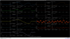
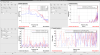
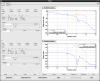
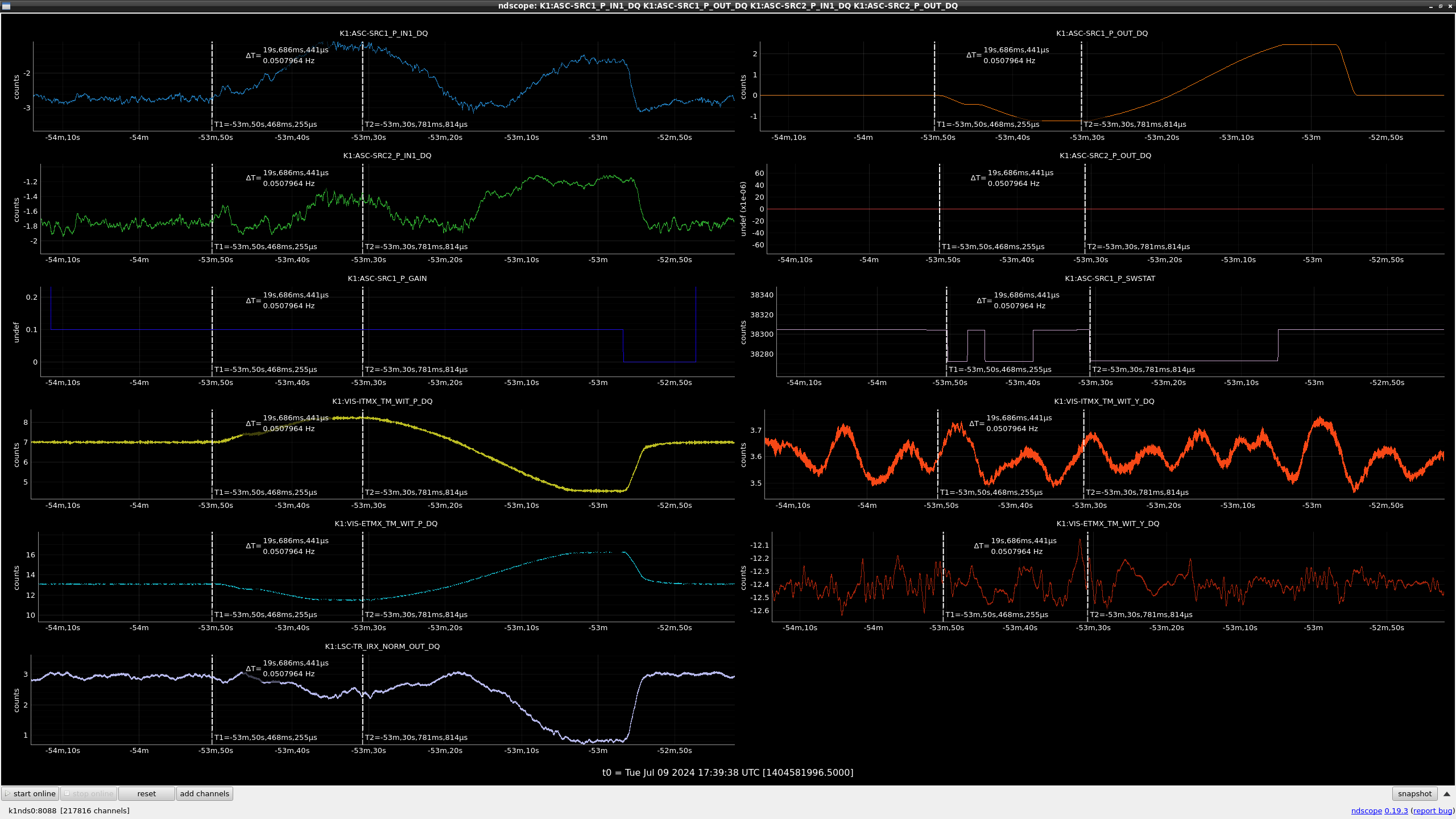
FIG: Time series when trying to control XHARD_PIT. The first x-axis line is when the control is switched on and the second x-axis line is when the sign is converted. This control is designed with a 0.1 Hz UGF, but at this time it is a more slow control with a gain of 0.1. At first, the error signal (SRC1_IN1 signal) was close to 0, but the transmition power was reduced. When the sine was converted, the transmission power was increased, but not close to 0 at the error signal. However, as the error signal increases more and more, it exceeds the peak transmission power, so the transmission power drops again.
I will organise the details tomorrow and review the control set-up and measurement methods. However, I did not measure the sensing matrices of all degrees of freedom, so I did not check the couplings of the other freedoms. It is possible that some degree of freedom coupling has not been removed.
I will post details tomorrow.
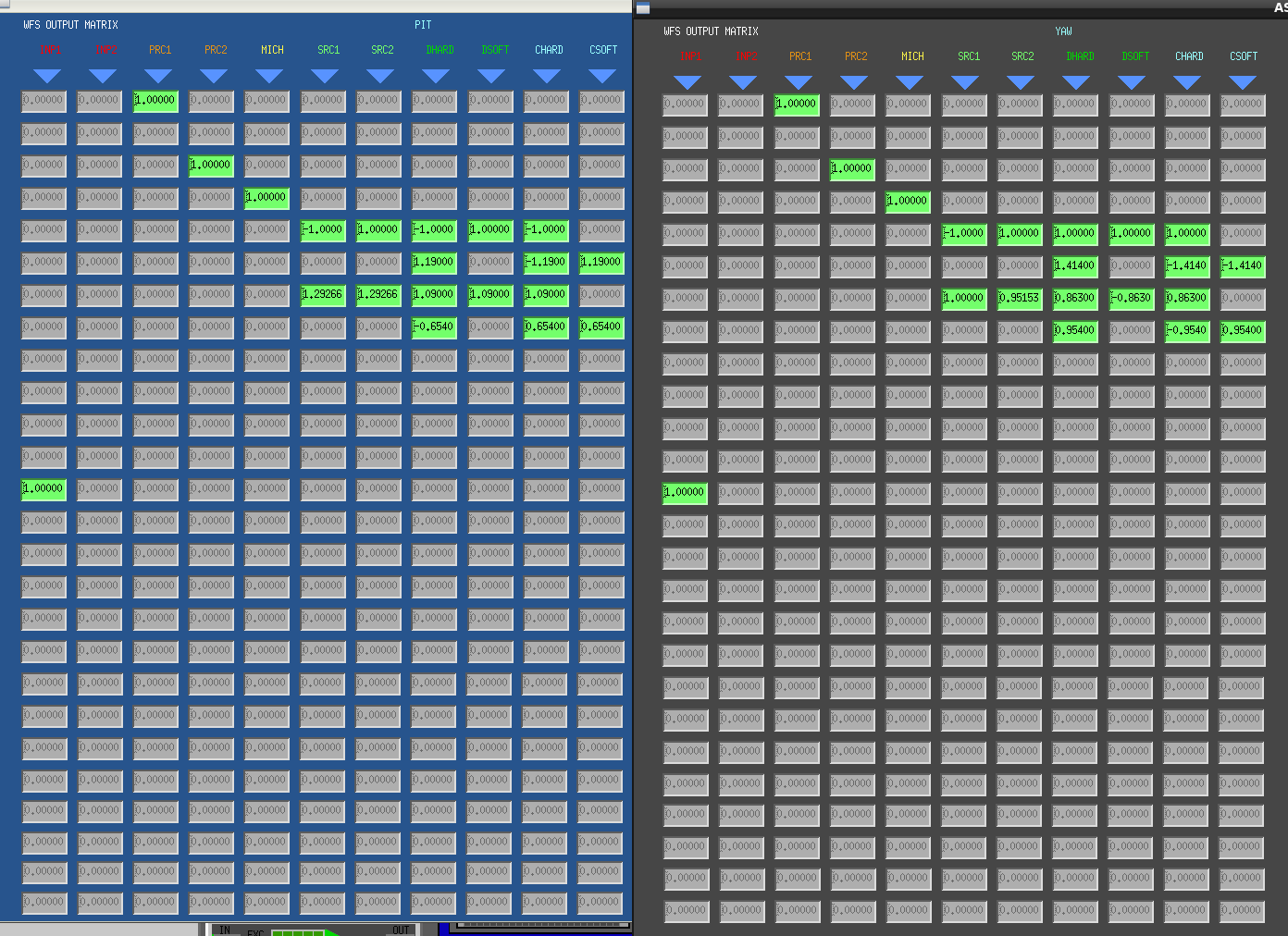
Summarised what I did on this day, set to XHARD: SRC1, XSOFT: SRC2.
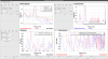
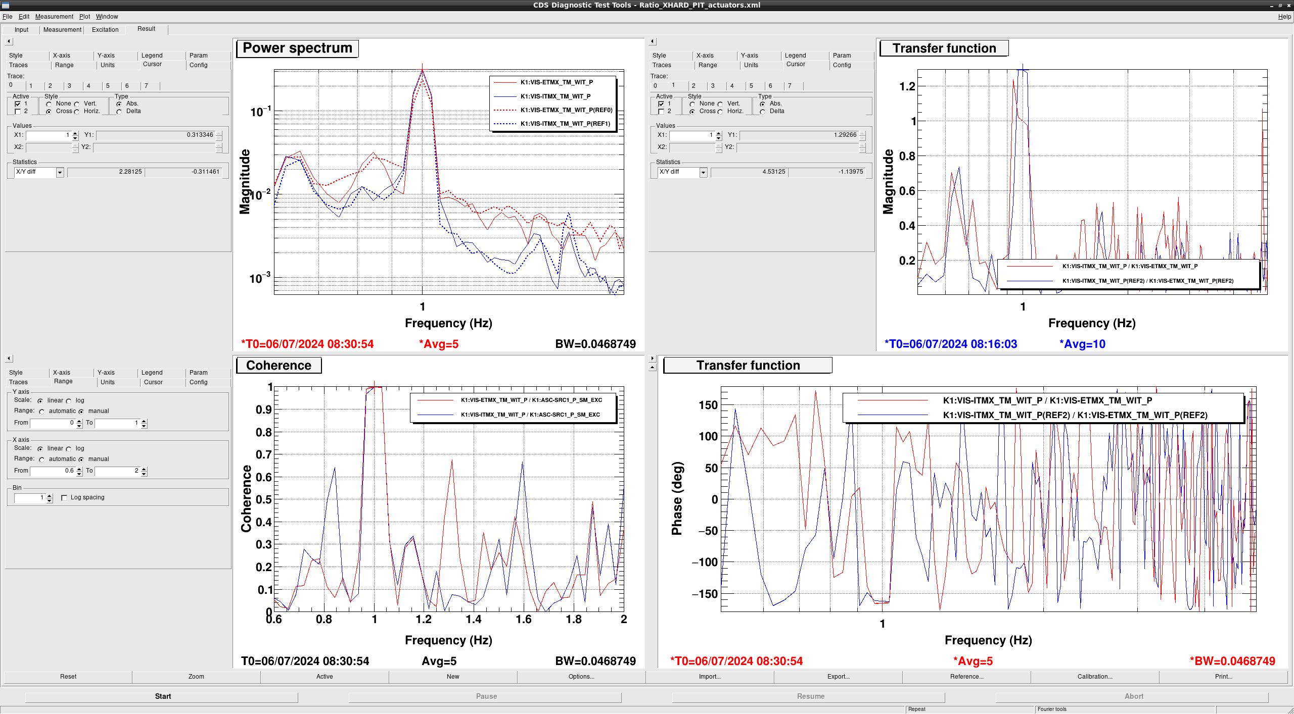
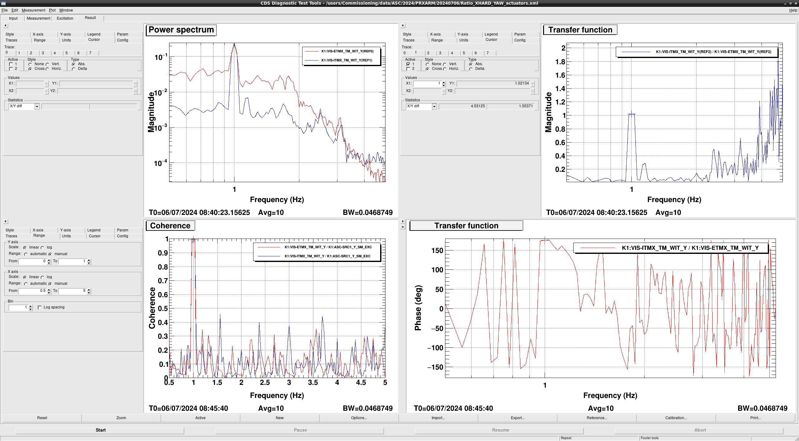
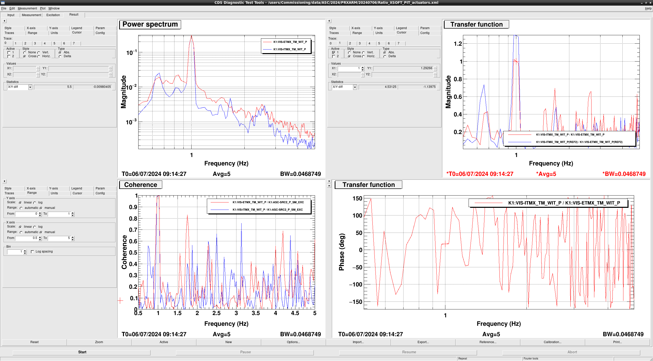
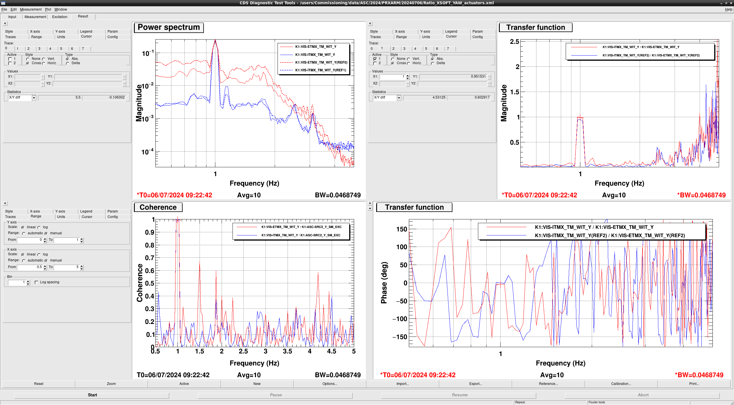
- Measurement ratio of each DOF actuators at 1Hz
Measured its ratio to tilt the same amount as ITMX and ETMX. REF setting the ratio of ITMX to ETMX to 1, subsequent measurements are after inserting the parameters.
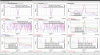
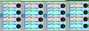
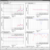
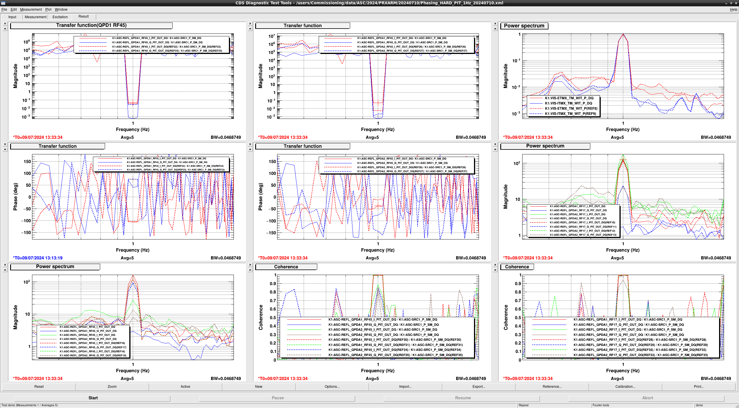
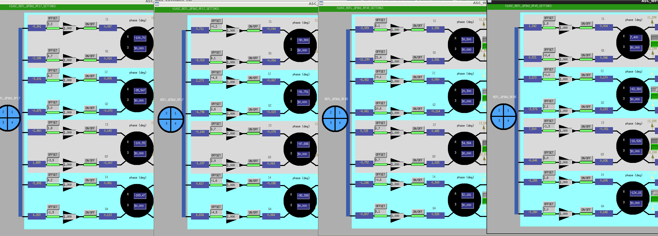
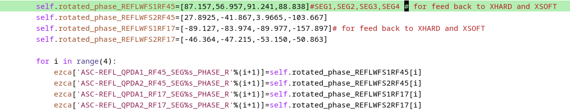
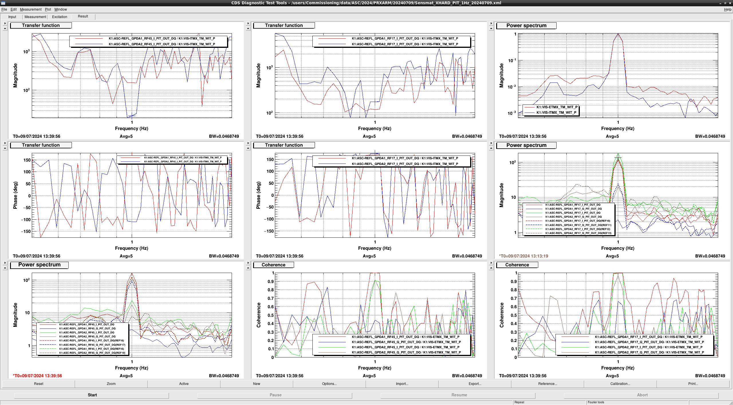
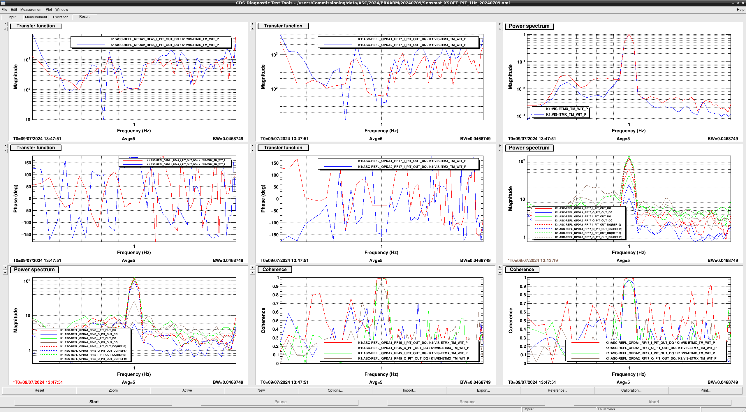
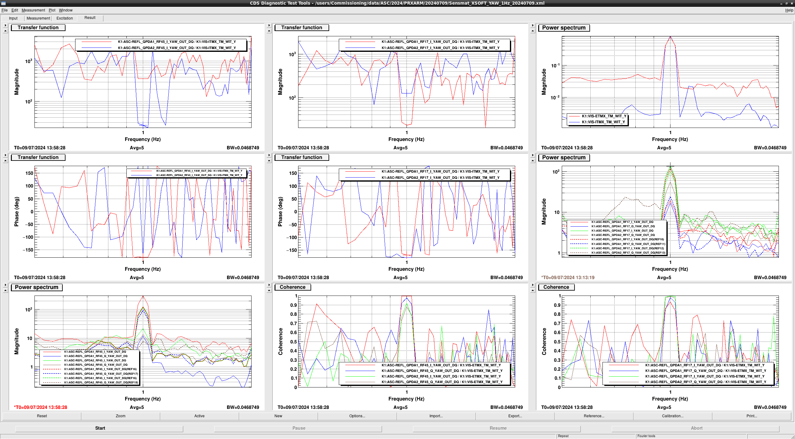
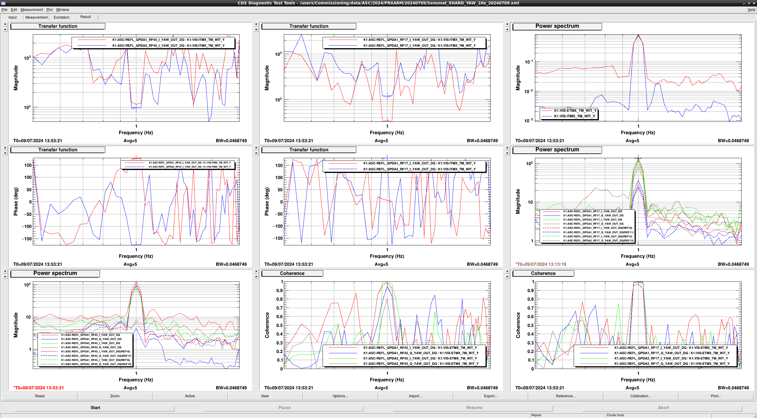
FIG1: XHARD_PIT, FIG2:XHARD_YAW, FIG3: XSOFT_PIT, FIG4:XSOFT_YAW, FIG5: inserted parameter - Phasing to erase the Q signal of REFLQPD{1,2}_{RF17,45} in XHARD_PIT.
In this time, the phase to be turned was obtained from the I and Q signals of the transfer function of the excitation signal. However, the phase of the transfer function in the excitation signal is not fixed at 0 or 180 degrees, so it was calculated without phase information.
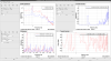
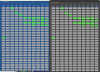
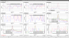
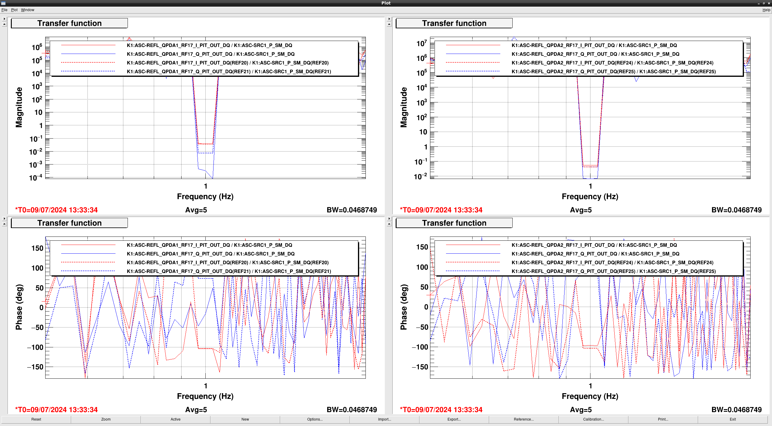
FIG6, FIG7 :REF before phasing, subsequent measurements after phasing. SEG8: the phase before phasing(Phase when measured.) FIG9: the turning phase(Now we can set the phase in "REFLWFS_ON_FOR_PRXARM"state of ASC_LOCK guardian) - Measured Sensing matrix(FIG10: XHARD_PIT, FIG11:XSOFT_PIT, FIG12: XSOFT_YAW, FIG13:XHARD_YAW)
HARD_PIT SOFT_PIT HARD_YAW SOFT_YAW QPD1_RF17 -117.57
61.828
35.0309
-22.9414
QPD2_RF17 -172.933
-40.541
-118.9079
-126.0031
QPD1_RF45 -157.549 106.966
-114.922
-376.829
QPD2_RF45 -21.800
-110.718
-97.013
-25.483
However, due to the bad coherence of QPD2RF45 of XHARD_PIT and QPD1RF17 of XSOFT_YAW, it was decided to use RF17 of QPD2 of REFL and RF45 of QPD1.
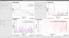
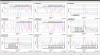
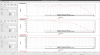
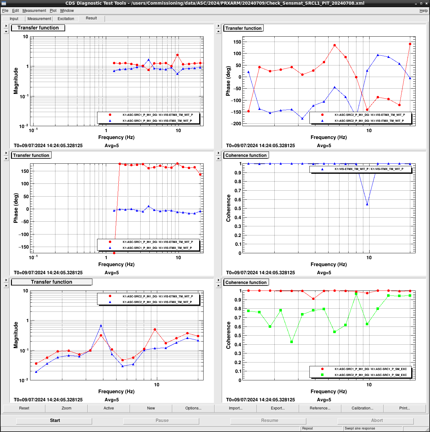
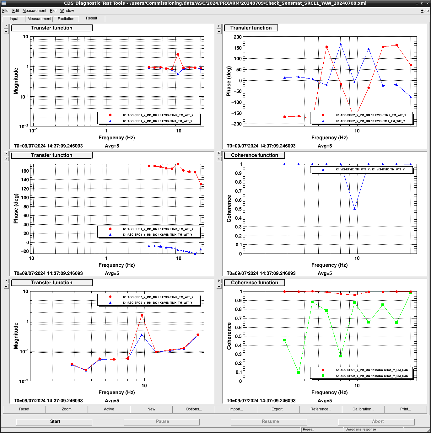
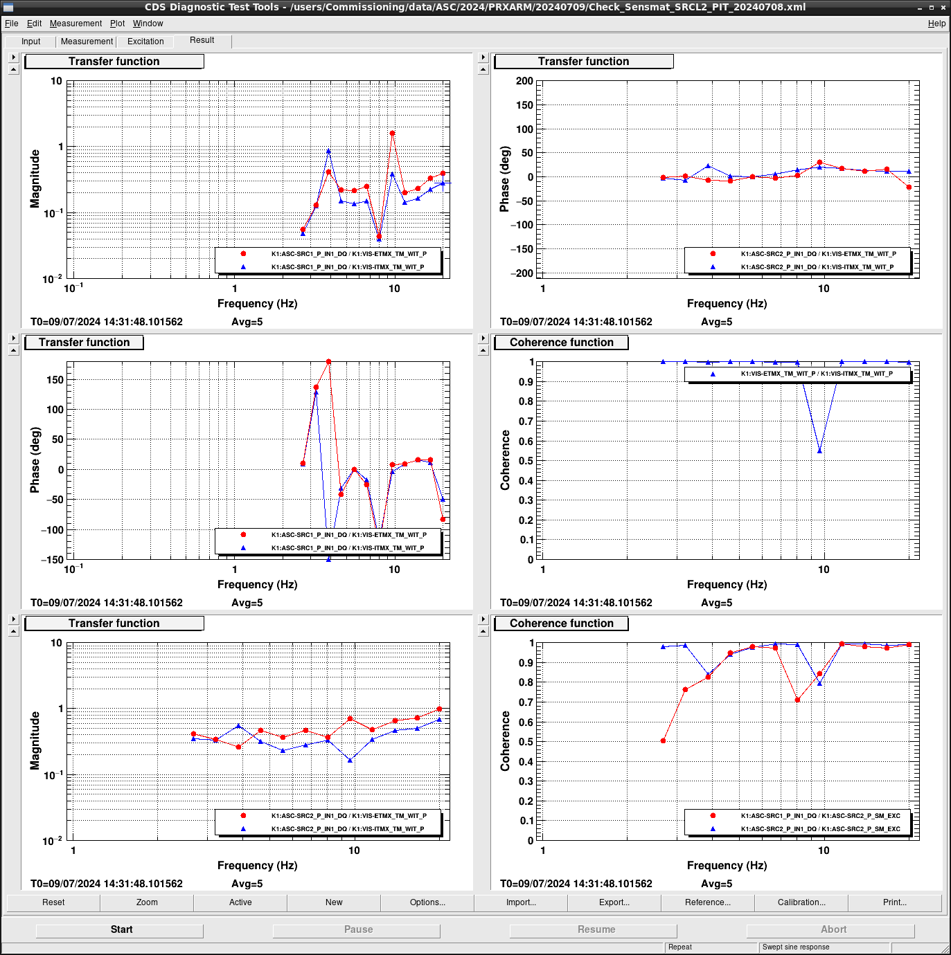
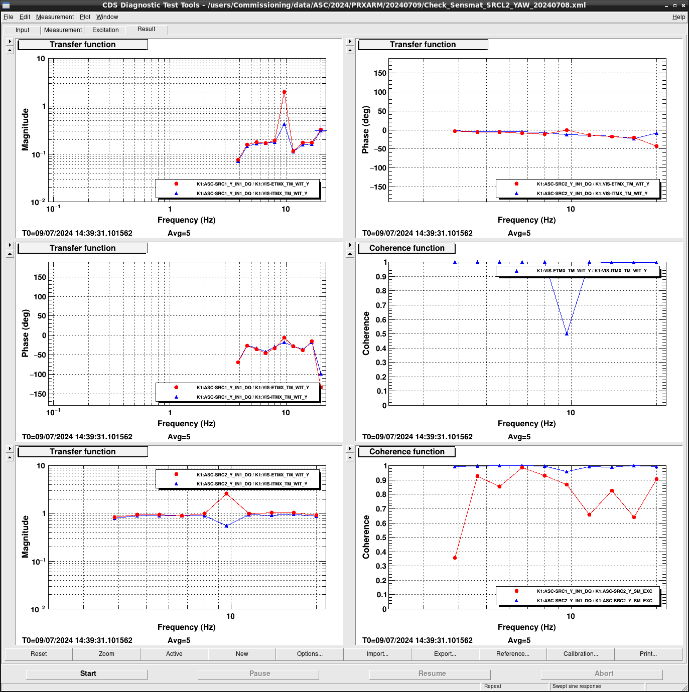
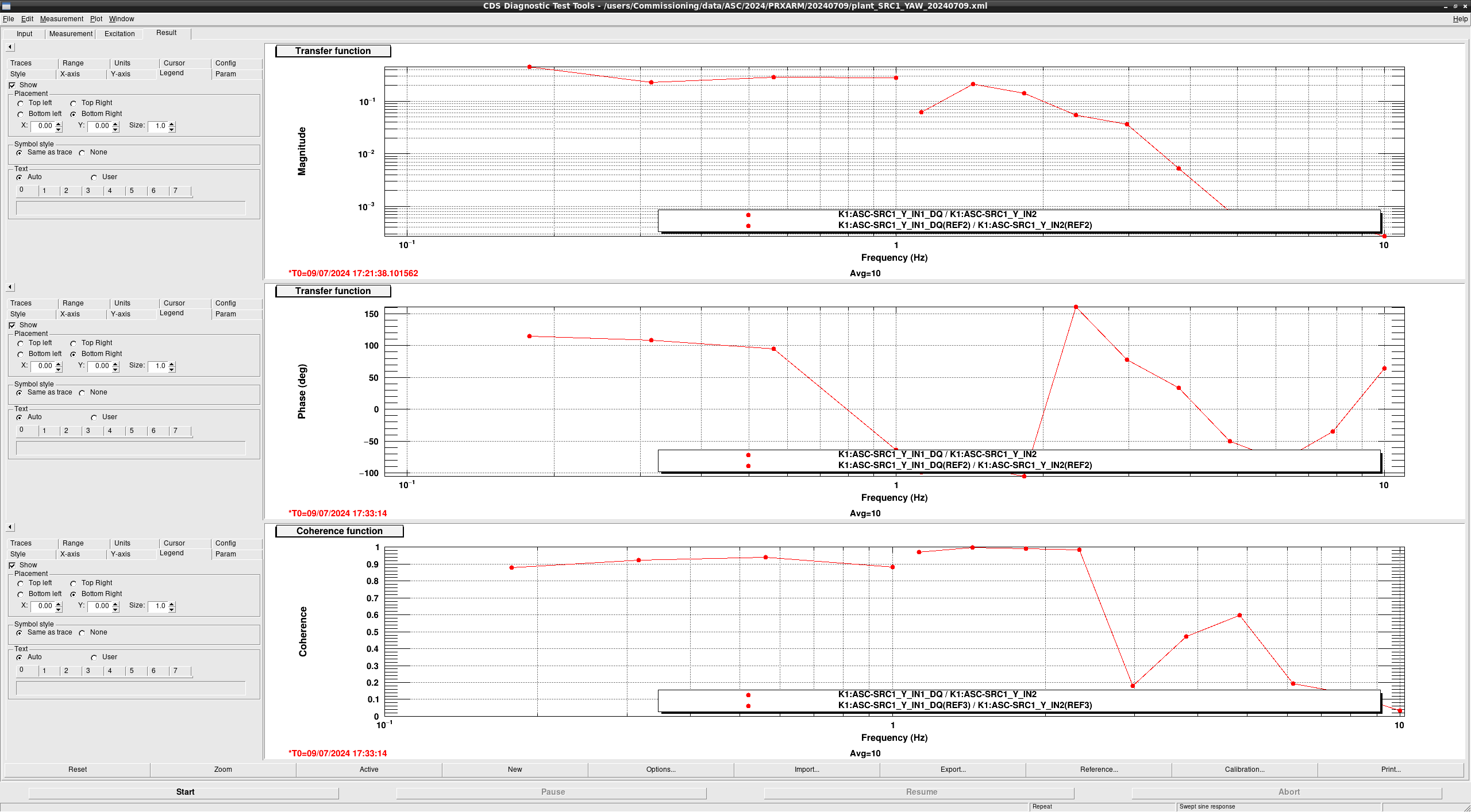
- Checked signal spespared(FIG14: SRC1_PIT, FIG15:SRC1_YAW, FIG16: SRC2_PIT, FIG17:SRC2_YAW)
Each degree of freedom is detected to 1 for the oplev signal. - Set VIS oplev signal
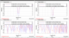
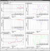
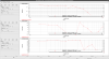
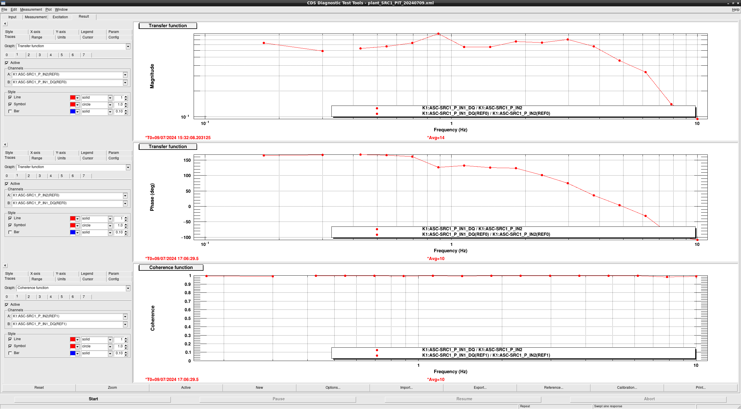
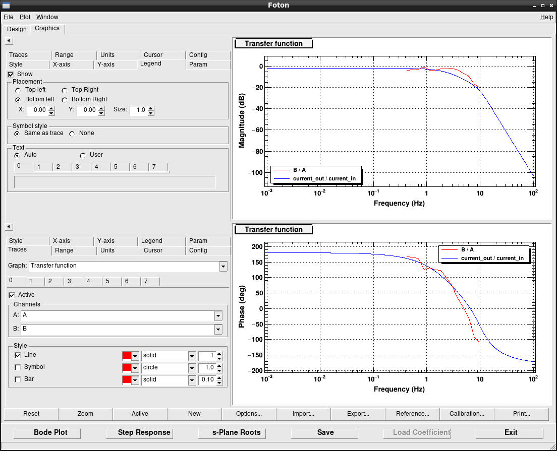
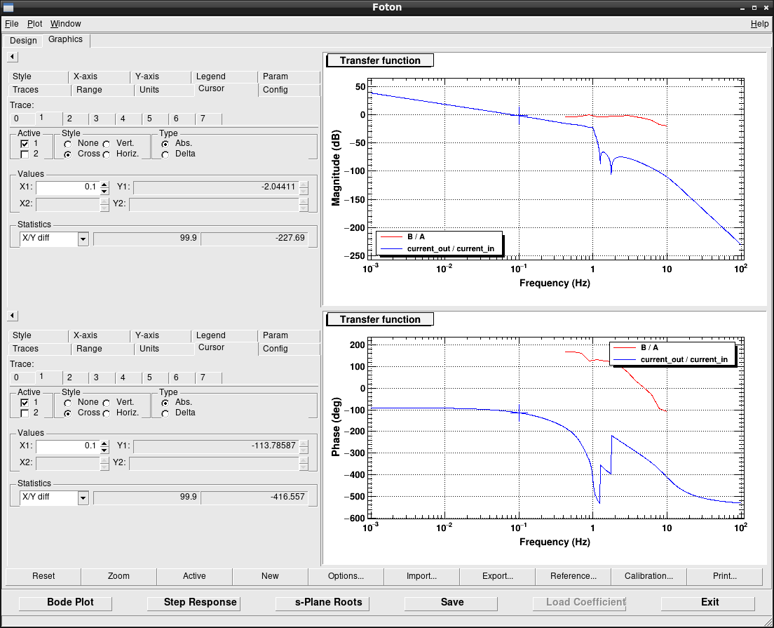
TM_ISC2OPLEV filter input ON and TM_LOCK filter input OFF for feedback to the peoplev signal - Measured plant of PIT signal(FIG18: SRC1_PIT,FIG19: SRC2_PIT)
- Set the plant and feed filter in SRC1_PIT(FIG20:The red line imported FIG 18., FIG21: Set integrator and elp filter at UGF 0.1 Hz.)


