Reports 1-1 of 1 Clear search Modify search
IOO (OMC)
yoichi.aso - 22:05 Thursday 20 June 2024 (30028) Print this report
OMC alignment

Takahashi, Washimi, Michael, Logan, Aso

Summary

The AS beam is introduced to the OMC. QPD1 is centered. QPD2 is centered in Pitch but miscentered by a few mm in Yaw.

Procedure

The alignment work was done with the X-arm locked and ITMY misaligned.
When the laser power was increased to 8W, X-arm was not locked (single bounce by ITMX).
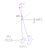
SR2 alignment

We used the aperture iris in the OMMT chamber as a reference for the SR2 alignment.
First, we set the opening of the iris to be ~3mm diameter. Then we moved the SR2 in pitch and yaw while watching the power detected by the PD behind the iris. SR2 was set to the orientation to maximize the power on the PD.
We accepted the new set point values of the SR2 OpLev DC loops in SDF.

OMMT1 alignment

We aligned the OMMT1 to center the OMMT2 trans QPDs.
Since the OMMT2 transmission is extremely weak, we increased the IMC transmission power to ~8W.
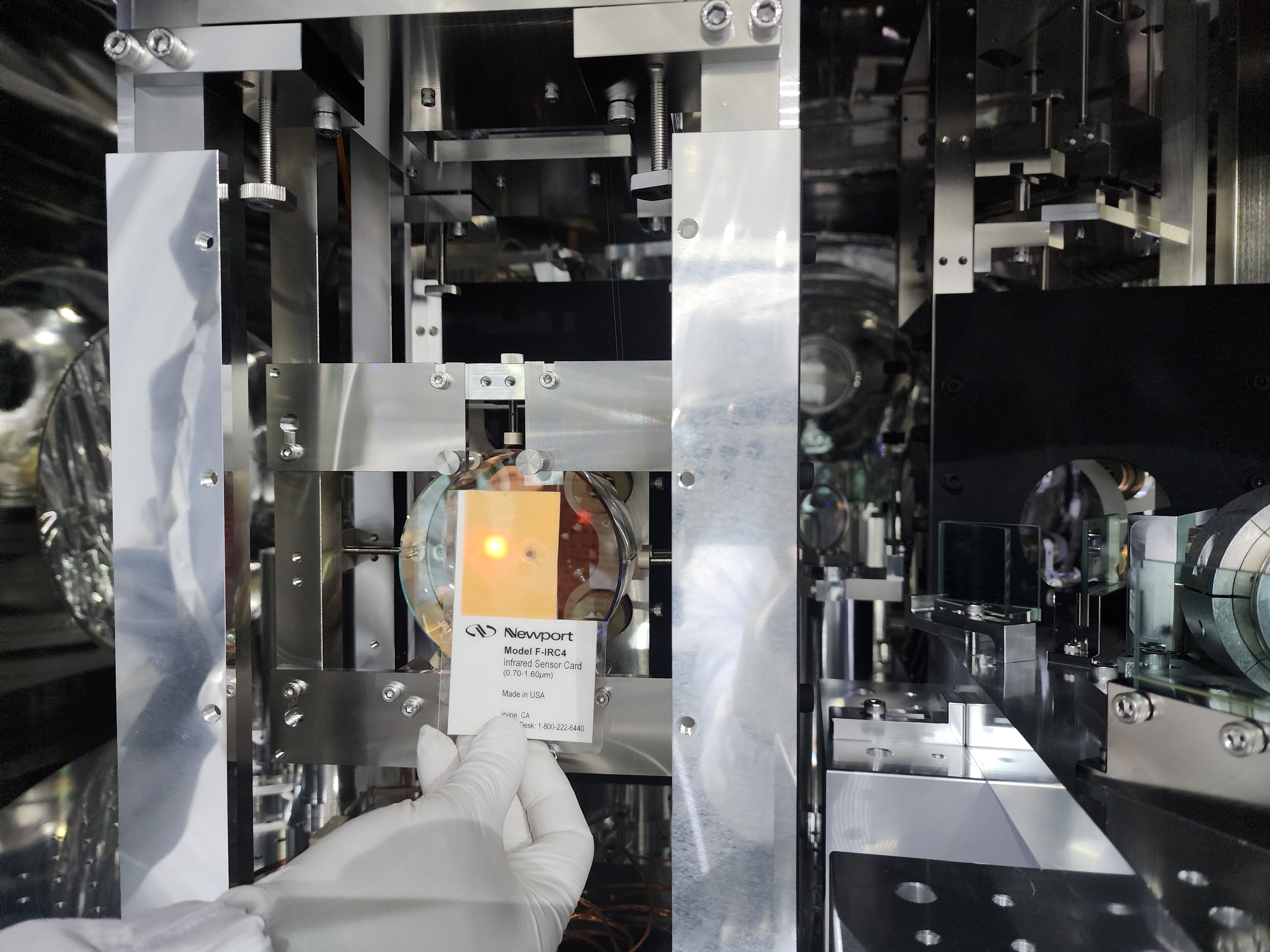
With the ceiling light turned off, we were able to see the transmitted beam.

Since the beams were largely miscentered in Yaw, we rotated OMMT1 frame with a pusher.
This is because we did not want to use the picomotor, which will change the OSEM offset.
For pitch, we had to use the picomotor. Fortunately, the required adjustment was small. So the OSEM DC values remained good.

OMMT2 alignment

We checked the beam at the input of the OFI.
It was almost perfectly centered in Yaw, but shifted by a few mm in Pitch. 
So, we used the OMMT2 picomotor to center the beam on the OFI.

Alignment of OMC with OSTM

Since OSTM was re-suspended, the beam going to the OMC was largely missing the target.
We rotated the OSTM in Yaw with a pusher.
For Pitch, we had to use the picomotor.

We were able to hit the center of QPD1 with the above adjustment.
In this state, the beam on the QPD2 is almost perfectly centered in Pitch, but miscentered in Yaw by a few mm.

Since we had to move the OSTM picomotor in Pitch by a lot, the OSEMs are now out of range.
We need to re-adjust the OSEM positions tomorrow.

Next step

We are planning to shift the position of OSTM with a pusher.
Combination of the shift and rotation of OSTM should allow us to center both QPD1 and QPD2 at the same time.


Images attached to this report
Comments to this report:
yoichi.aso - 0:23 Saturday 22 June 2024 (30058) Print this report

Washimi, TakahashiR, Akutsu, Aso

We continued the OMC alignment work.

QPD centering

As is shown in my beautiful hand drawing below, the beam going through the OFI is reflected by OSTM then split by a BS and received by QPD1 and QPD2.

The beam on the QPD1 was centered by the rotation of OSTM yesterday.
However, the beam on the QPD2 was shifted toward the direction of the arrow indicated by the green dot.
It is convenient to work with the mirror image of QPD2 (red colored) by the BS plane. In the mirror image, the green dot is mapped to the blue dot.
The actual beam axis at that time was the line going through the center of QPD1 and the blue dot (the blue line).
This means the location of the OSTM was shifted to the right (blue mirror) from the ideal position (black one).
Therefore, we needed to move the OSTM in the direction indicated by the green arrow.

We did exactly that using pushers.
We pushed the OSTM frame to the left with one pusher. Rotated the OSTM in Yaw with another pusher to center the beam on QPD1.
We then checked the beam spot position on QPD2 with the IR camera (SONY alpha 7s). The beam gets closer to the center of QPD2.
After a few iterations, we were able to center both of the QPDs.

OMMT1 shield plates

After the OMC QPDs are centered, Akutsu-san attached the shield plates on OMMT1.
https://klog.icrr.u-tokyo.ac.jp/osl/?r=30050

X-arm alignment

We noticed that the X-arm transmission was low (~0.6).
Ushiba-san aligned the X-arm during the lunch time. The transmission recovered to near 1.

Since the upstream alignment was changed, we re-aligned SR2 with the iris in the OMMT chamber.
Then we centered the OMMT2 trans QPD with OMMT1.
After doing these, OMC QPDs started to receive beams again.

Aluminum foil covers

Since the wind from KOACH filters moved the OMMT1 and OMMT2 suspensions too much, we put aluminum foils on the flanges between the OMC and OMMT chambers.
We made small holes on the foils to let the beams go through.
This allowed us to fine adjust the centering of the OMC QPDs. We used OMMT2 and OSTM picomotors for this.

OSEM adjustment

Takahshi-san adjusted the OSEMs of the OSTM because they were completely out of range after the OMC QPD alignment.
The TF measurements after the adjustment showed strange shapes.
Takahashi-san found that EQ stops on the TM were in contact with the mirror.
Retracting these EQ stops recovered the transfer functions back to the normal state.

OSTM shield plates

Akutsu-san re-installed the shield plates for OSTM.
https://klog.icrr.u-tokyo.ac.jp/osl/?r=30050

QPD centering servo

We were able to engage the centering servo of OMMT2 trans QPD.
However, we could not engage the OMC QPD centering servo. Somehow, the loops went crazy.
We did not spend enough time to investigate this problem.

OMC flash

By moving the PZT slider manually, we were able to see the flashes of the OMC with the OMC trans DC PDs.
The OMC trans. camera seemed to be not centered (no flash image could be seen).

Beams on the AS table

We checked the beams coming out of the OMC chamber.
The OMC REFL beam can be seen at the periscope. So the beam path seems to be reasonably preserved.
The AS RF beam was not found on the AS table. We found that the OSTM transmitted beam was missing the steering mirror.
We need to readjust the position of this steering mirror.


Images attached to this comment
Search Help
×

Warning

×