Abstract
Before updating the MC calibration on the front-end model, I made a calibrated spectra with 65kHz test points.
Difference from the current front-end calibration comes from difference in the actuator efficiency of PZT (3.0MHz/V on front-end 4.5MHz/V on offline).
(As we already knew,) we need to know the absolute value of PZT efficiency accurately, which varies largely in each measurement.
Details
I couldn't conclude that we can trust values in latest measurements (klog#29194) and update the front-end calibration in the posts of this thread, I made a calibrated spectra and compared with the front-end calibration. Because calibrated spectra with DAQ-ed error and feedback signals in 16kHz cannot show around the cross over frequency of PZT and EOM loop (~15kHz), I used 65kHz test points instead of {MIXER,FAST,SLOW}_DAQ_OUT_DQ.
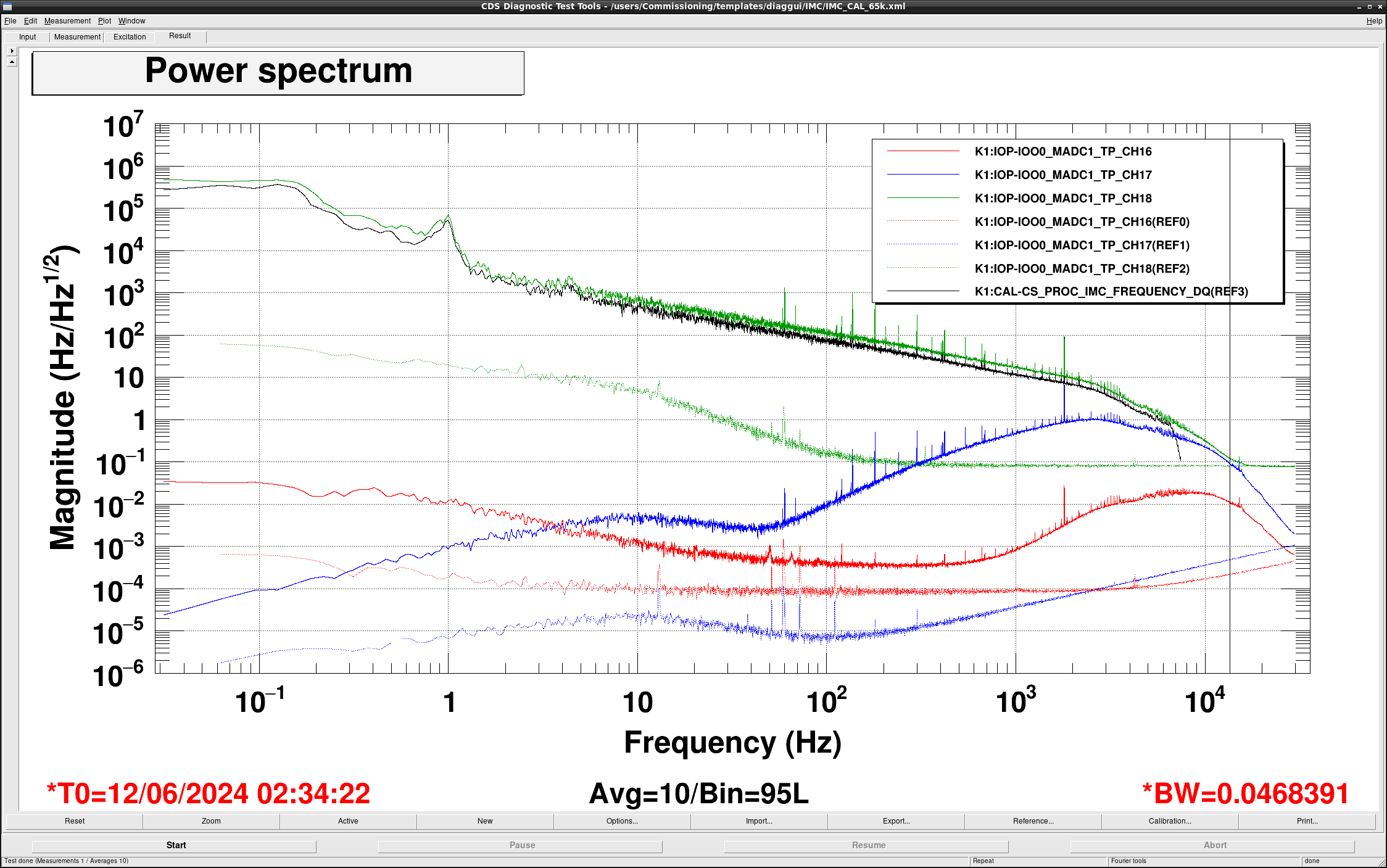
Figure 1 shows the calibrated spectra by using the error signal (red curve), feedback signal to EOM (blue curve), feedback signal to PZT (green curve) and the front-end calibrated signal (black curve). Dashed lines represent an ADC noise level equivalent to the frequency noise. Though a strict comparison should be done with the black curve and a sum of the red, blue, and green curves, almost all frequency (0.1Hz - 15kHz) can be represented only by PZT feedback. On the other hand, PZT feedback signal is limited by the ADC noise above ~15kHz. So it's difficult to check around the cross over frequency of PZT and EOM loops even when we used 65kHz test points. Because some circuits (AA, Universal whitening filters etc.) have poles around 10kHz, seeing such high frequency region requires a modification of circuit design such as the beacon system.
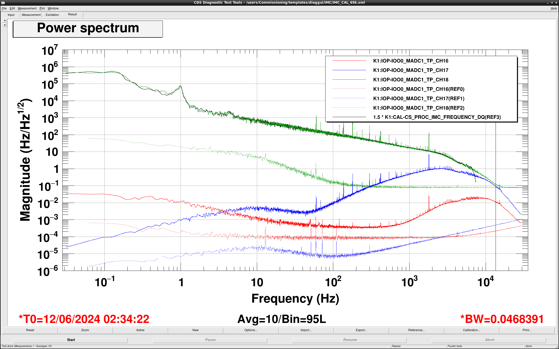
In figure 2, I applied a factor of 1.5 to the calibrated spectra by the front-end calibration on diaggui to compare with calibrate PZT feedback signal and front-end calibration. In front-end calibration, PZT actuator efficiency is set as 3.0MHz/V (klog#13012). On the other hand, latest measurement is 4.5MHz/V (klog#29194. So a factor of 1.5 comes from the ratio of these two measurements. Though we can compare only below 8kHz because front-end calibration is done in 16kHz sampling, black and green curve match well. So applying latest and accurate PZT efficiency is an only remaining issue for the update of front-end calibration.
Past measurements are as follows and they have inconsistency as a factor of 3-4 in maximum. We need a measurement way that has a consistency and reproducibility. According to the discussion with Ushiba-kun, using FSR or sideband of PMC with PZT excitation may be better than past measurements.
- 1.48MHz/V klog#2853
- 3.0MHz/V klog#13012
- 5.56MHz/V klog#16678
- 4.5MHz/V klog#29194
-----
Memo
Error signal (MADC1_TP_CH16)
gain = 1 / optical_gain[V/MHz] / whitening_gain[V/V] / generic_filter[V/V] /single2diff [V/V] / ADC[ct/V]
- optical_gain = 17.9V/MHz (klog#29194)
- whitening_gain = 21dB V/V
- generic_filter = 101V/V
- single2diff = 2.0V/V
- ADC = 1638.4ct/V
pole:
- cavity_pole = 5.74kHz (klog#29193)
EOM feedback (MADC1_TP_CH17)
gain = eom_gain[rad/V] * phase2freq / single2diff[V/V] / ADC[ct/V]
- eom_gain = 0.34rad/V (klog#29194)
- phase2freq = 2*pi
- single2diff = 2.0V/V
- ADC = 1638.4ct/V
pole:
- anti-generic_filter = 10Hz, 10Hz
zero:
- anti-generic_filter = 100Hz, 100Hz
- phase to frequency = 0Hz
PZT feedback (MADC1_TP_CH18)
gain = eom_gain[rad/V] / single2diff[V/V] / ADC[ct/V]
- pzt_gain = 4.5MHz/V (klog#29194)
- single2diff = 2.0V/V
- ADC = 1638.4ct/V
pole:
- anti-generic_filter = 10Hz, 10Hz
zero:
- anti-generic_filter = 100Hz, 100Hz