Hirata, D. Chen, Akutsu
Summary
Did final check for the mid baffles of PR3. Some issues found but nothing we can do at this time.
Details
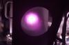
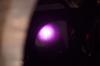
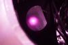
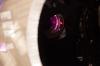
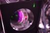
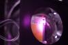
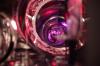
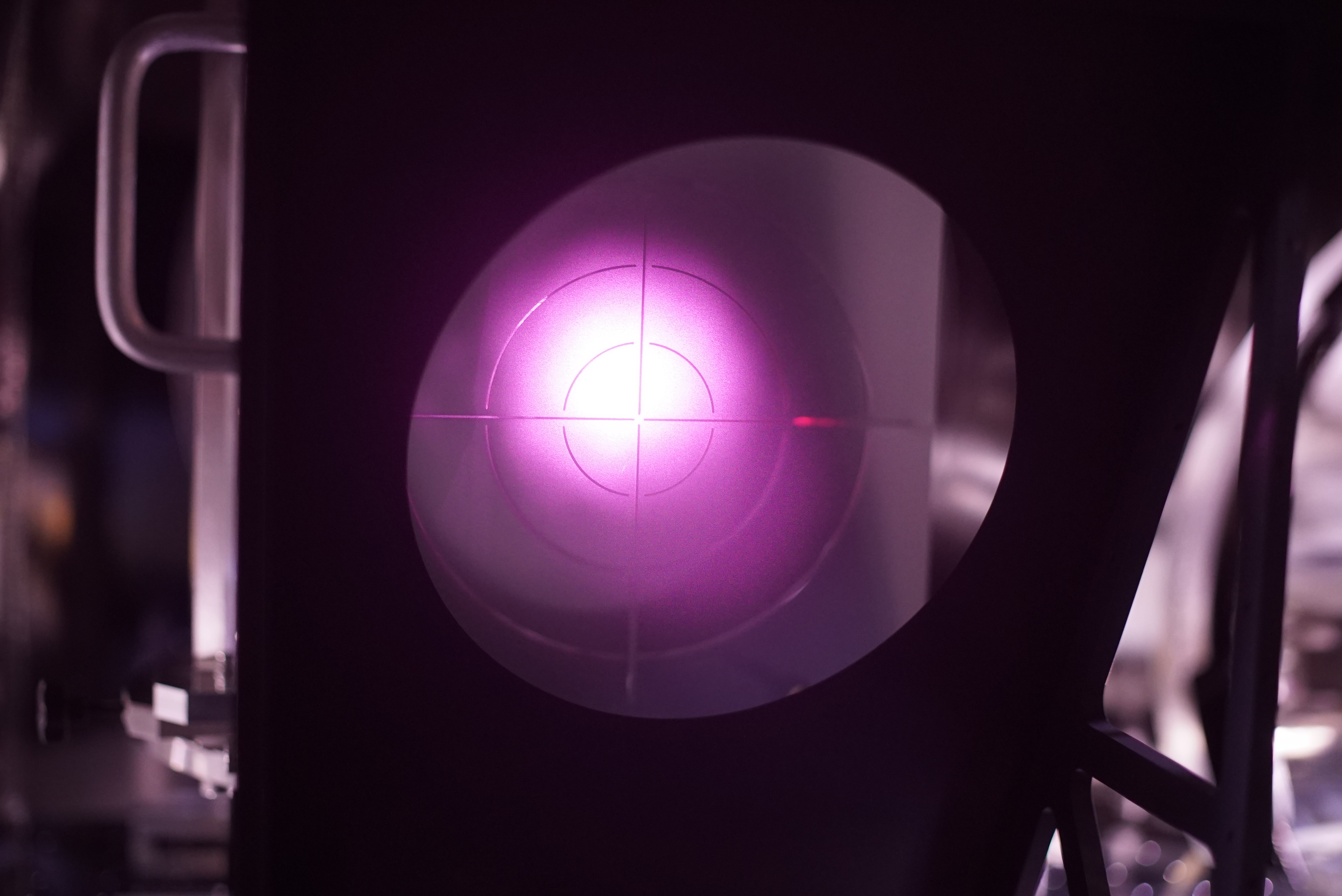
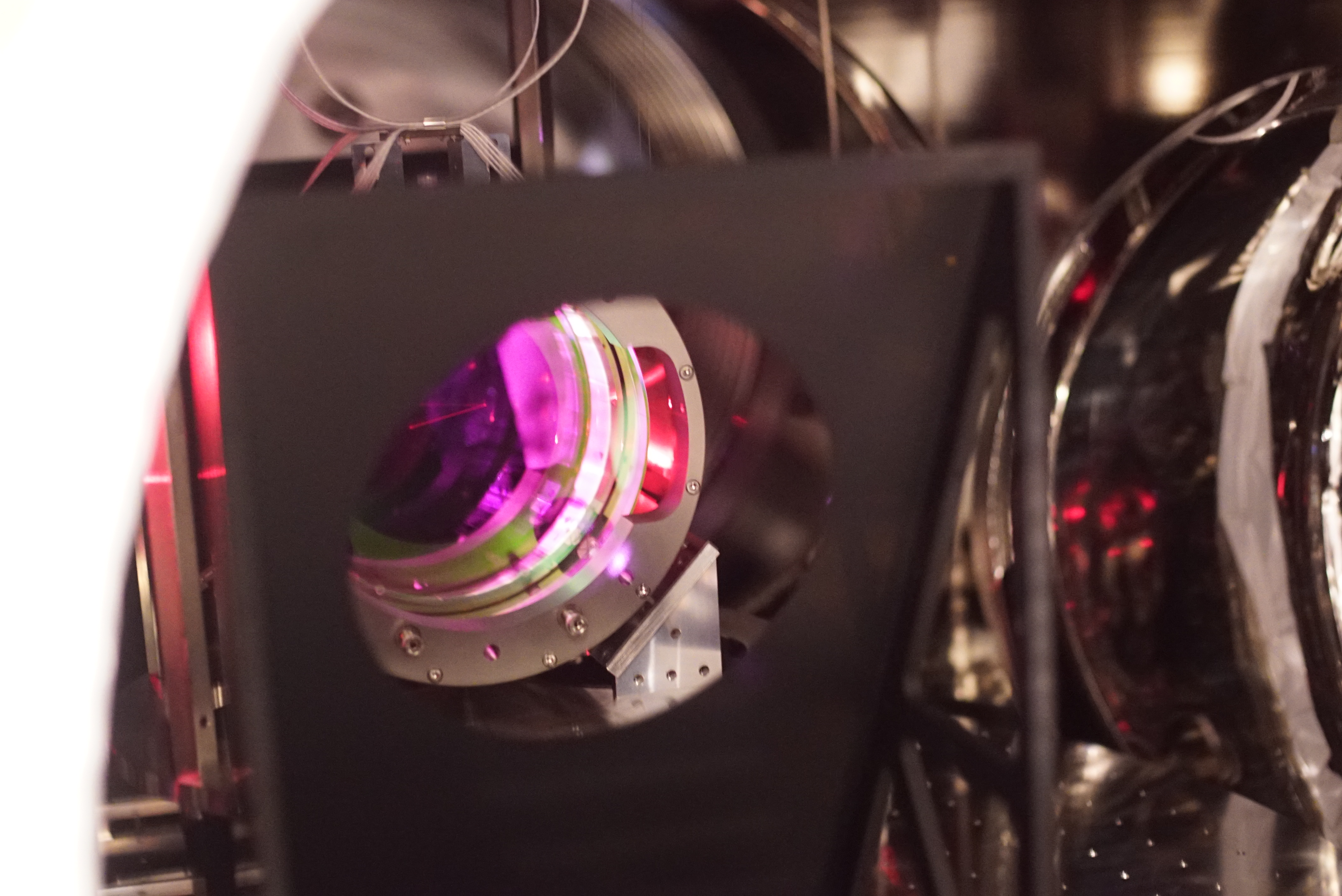
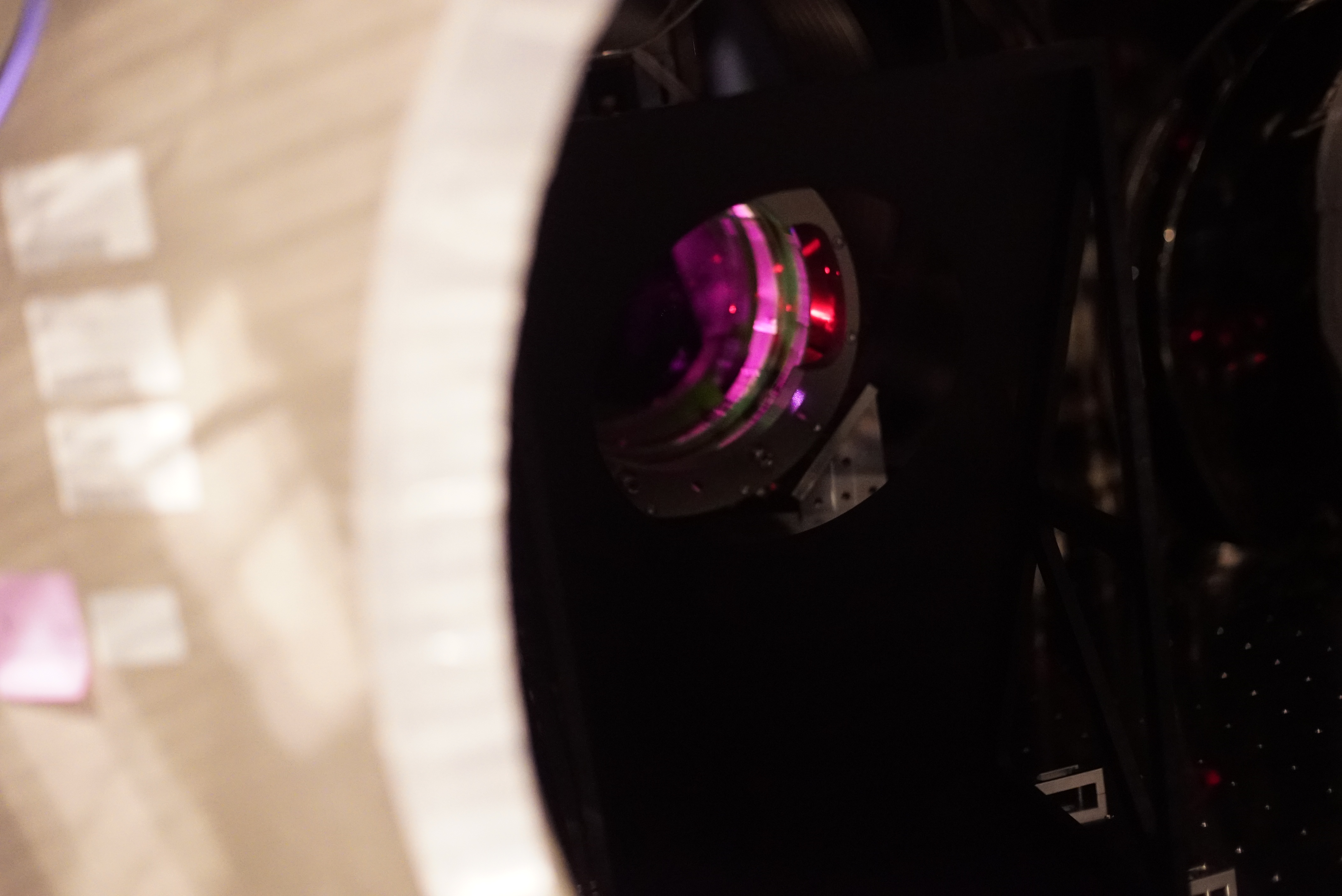
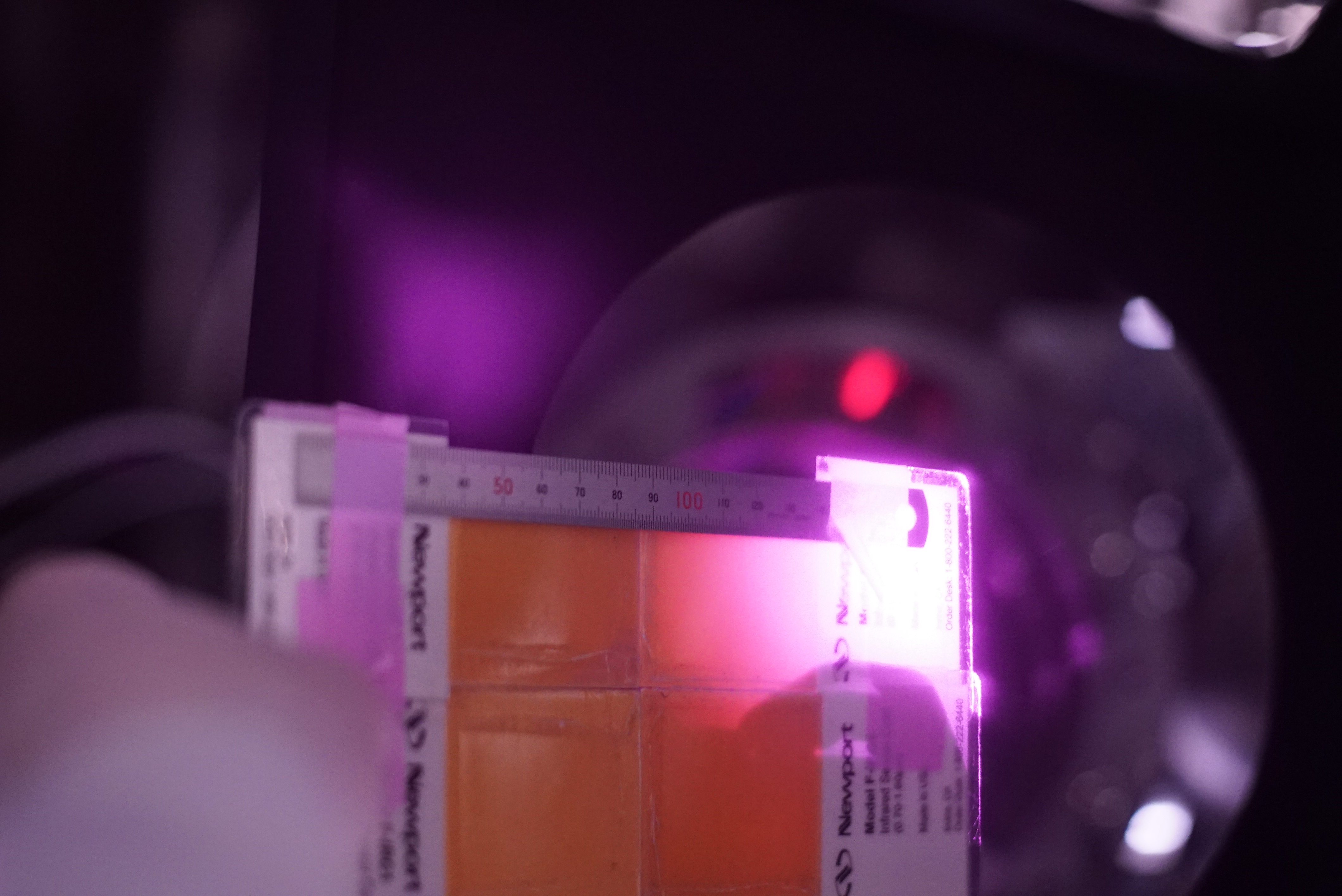
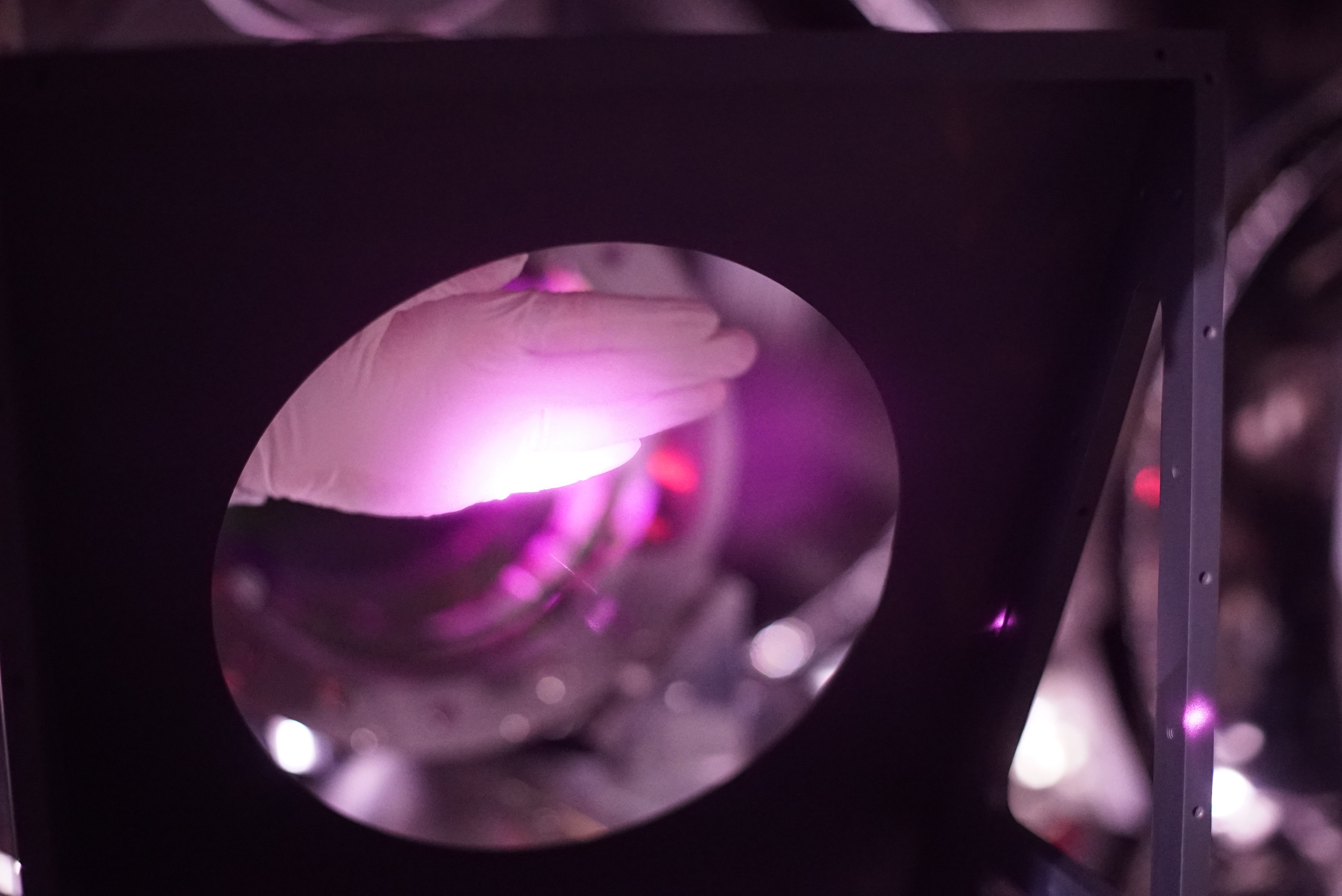
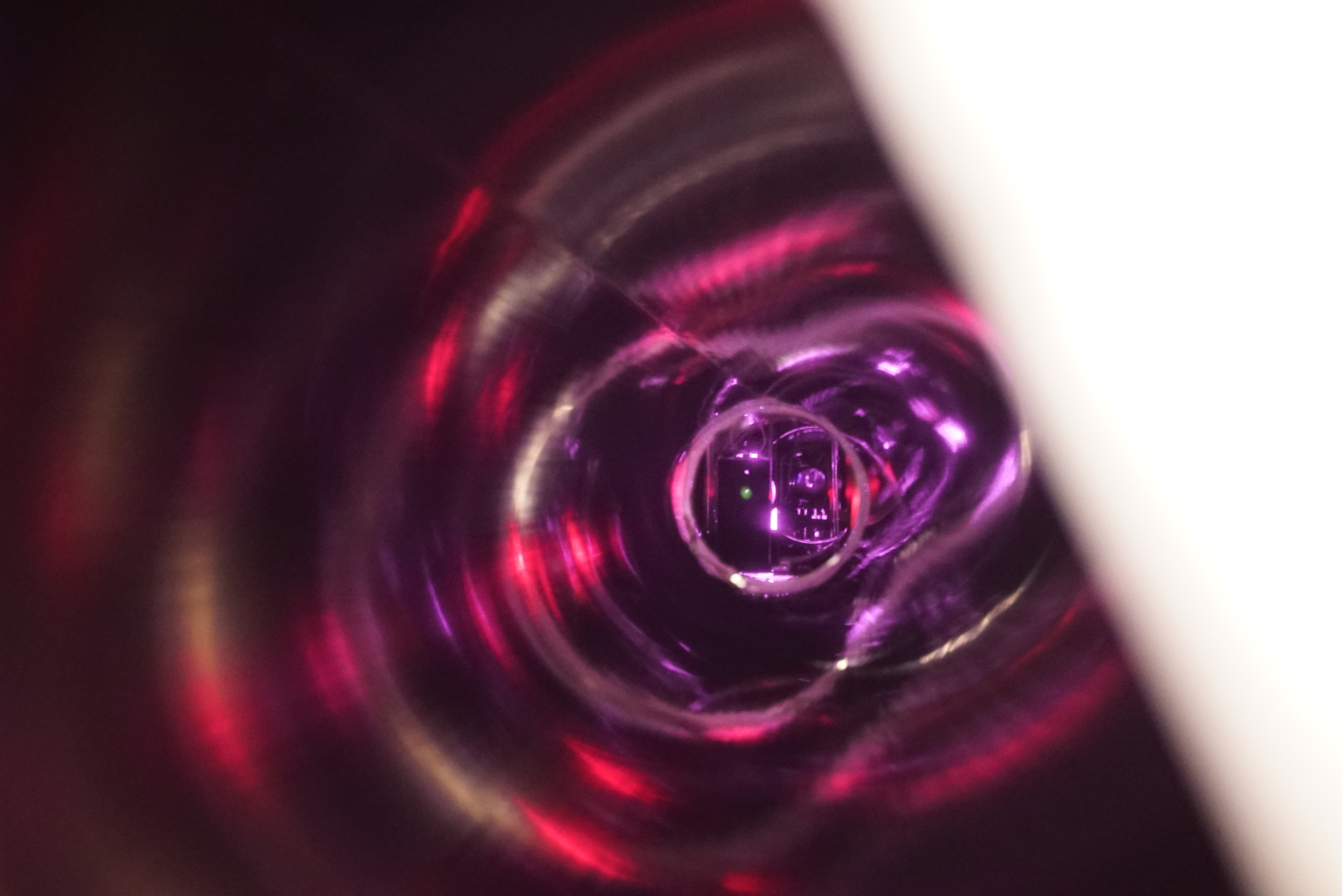
Make sure to PR3 state to be PAY_FLOAT. Then opened the PR3 chamber. Figs. 1-3 are the IR beam spot on the PR3 HR target. Here remind that the PR3 HR target plate was adjusted to its (target's) frame according to the reference lines on the recoil masses on PR2 and PR3 (by illuminating the both reference lines with a laser level; probably there should be a document by Hirata-san to explain this in JGWdoc); also note that the PR2's position when this target plate adjustement was done was different from the current one, as we have moved the PR2 suspension with its traverser in a few mm.Consideing that the nominal open angle between (the IR beam from PRM to PR2) and (the IR beam from PR2 and PR3) is ~0.02 rad (see 29334), the additional angle due to a few mm/ 11 m (here 11 m is the distance between PR2 and PR3) ~a few x 1e-4 rad, so would be negligible; in other words, if the beam from PR2 shoots the center of the PR3 HR target, then the beam would still hit around the PR3's center. By the way, remind that the beam postion on PR3 is determined by the X arm. Anyway, as shown in Figs. 1-3, the IR beam spot is illuminating upper left of the HR target. The more precise quantitative analysis from these photos will be done and reported by Hirata-san later, but in sense, the IR beam spot is off-centered about a few mm in the -Y direction (or yaw) and 20-25 mm in upward (or pitch).
According to Hirata-san's document (to be linked later hopefully), the nomial gap between the aperture on this HR mid baffle and the nominal entering and reflected beam 3-sigma width at PR3 is about 13.4 mm in both sides of yaw and about 18.7 mm in both side of pitch; so yaw should be ok, but pitch might clip in principle. One may wonder if moving the HR mid baffle upward to compensate this offset, but such a move might make the recoil mass illuminated by the IR beam. The recoil mass and the blackened baffle, which do you like to be illumiated by the IR beam??
One may wonder if moving PR3 itself upward, and the make the mid baffle follow. Ignoring time, this might work, but there is another concern. The current beam postiions on PR3 and X arm are the results of ASC during O4a, while we had set everything center-to-center when closing the chambers for O4a; in other words, the interferometer seems to prefer THESE beam spot positions; there might be lossy points at teh PR3 center to prevent the best PR gain. Anyway we are not sure so far.
Also today we did not have any tools to move the HR mid baffle upward. So, in short, we left the baffles as is.
Notes
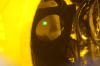
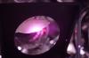
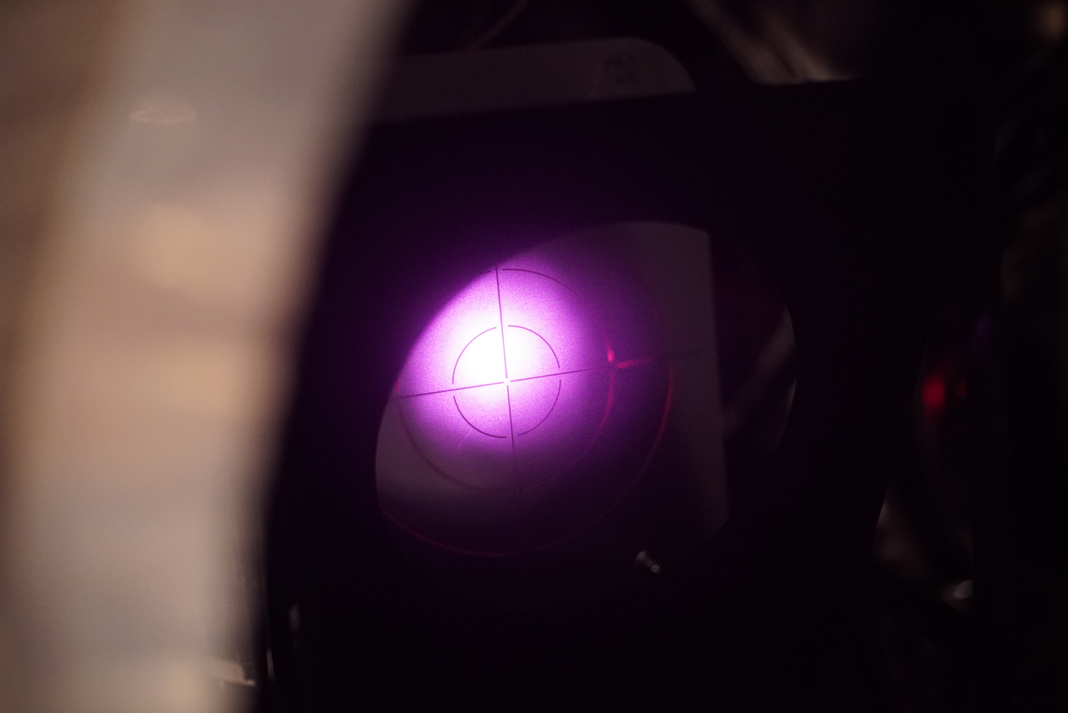
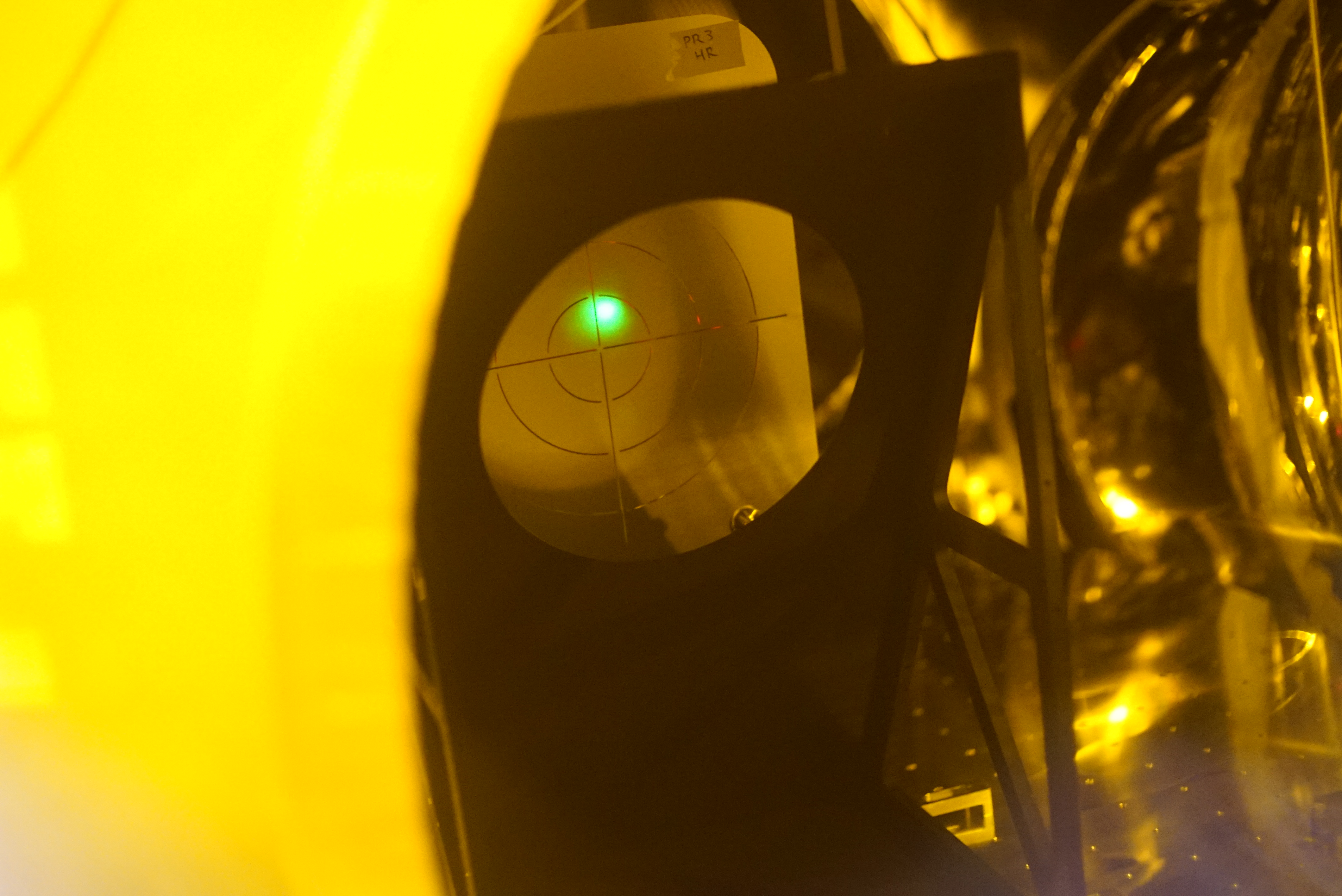
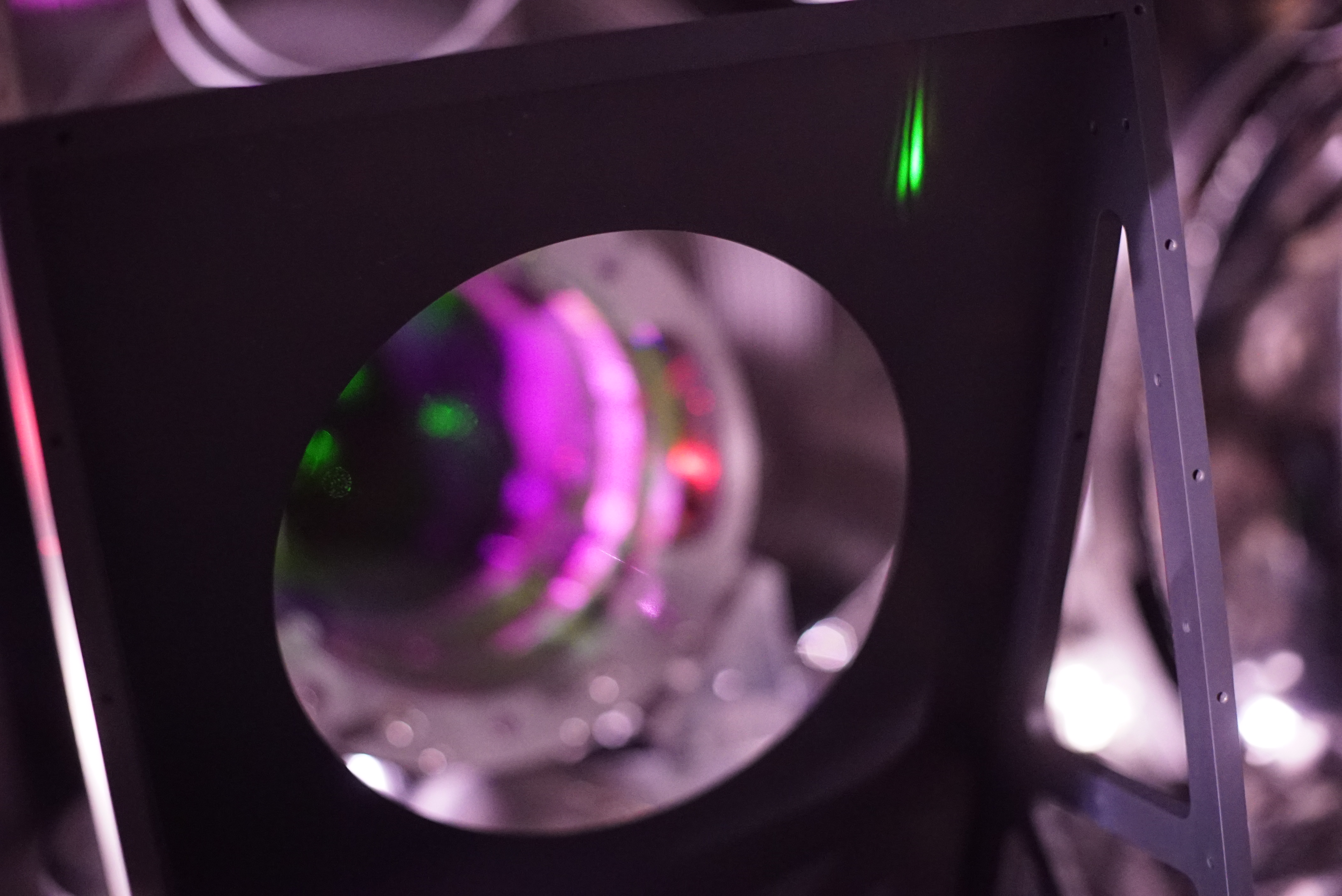
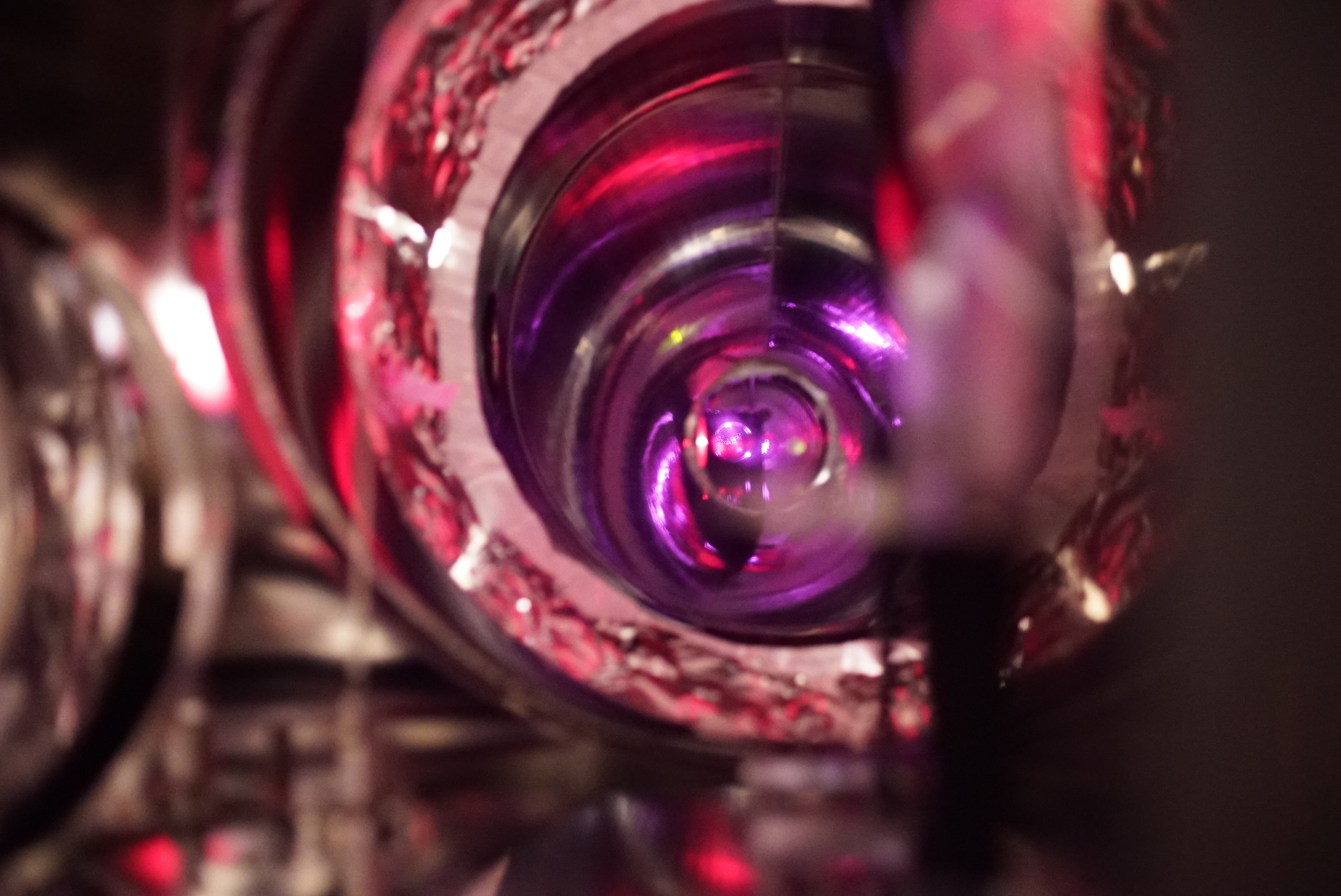
- Fig. 4 is the GrX spot on the PR3 HR mid baffle. Interestingly the green spot is off-centered in the opposite in yaw, while the same (as well as its amount, maybe) in pitch.
- According to Figs. 5-7, we could not see any symptons of apparent clipping around the baffle aparture. Because we did not request anything to ITMX, sometimes we could see that the IR (or even Gr?) spots reflected from ITMX were dancing around PR3. The major amplitude of the dancing would be due to that PR3's state was PAY_FLOAT. We once carefully call ALIGNED to PR3, and seemingly such dancing spots disappeared.
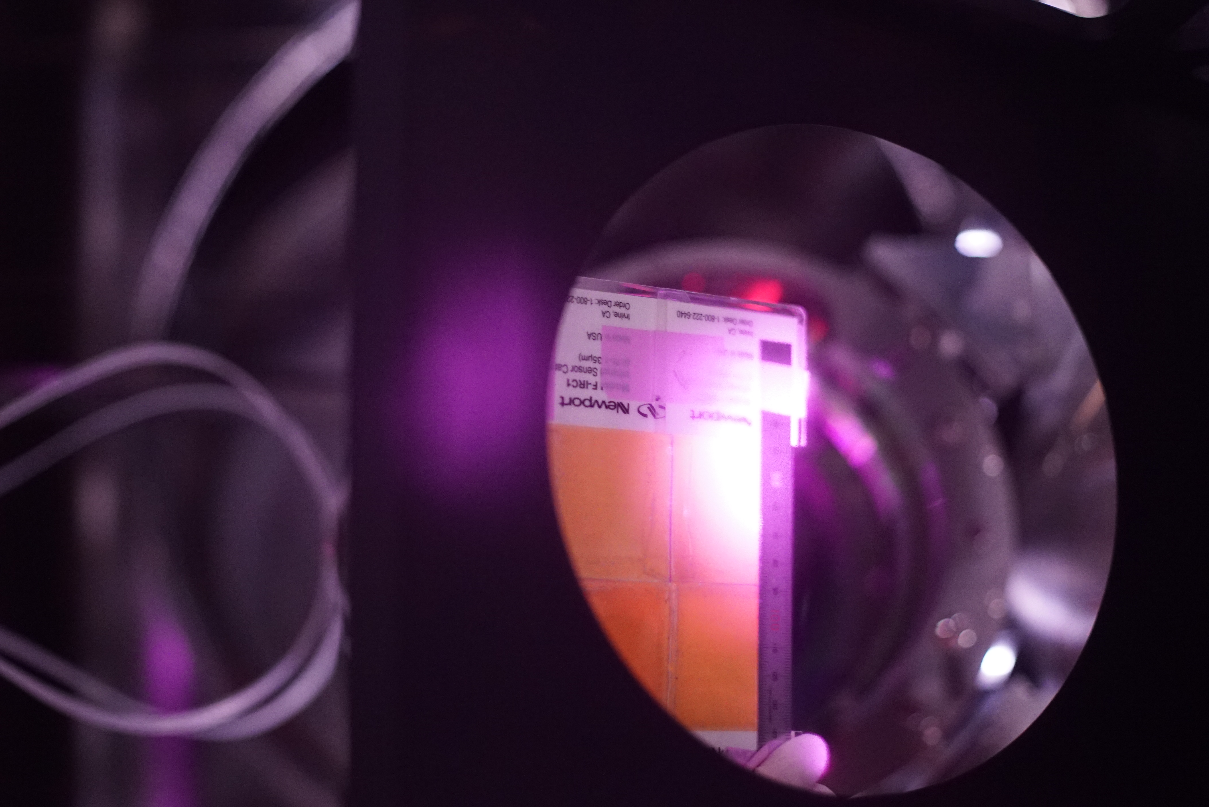
- Figs. 8 and 9 show that the IR beam spot's tail whose intensity can be seen with the sensor card are well within the aparture. Fig. 10 by hand.
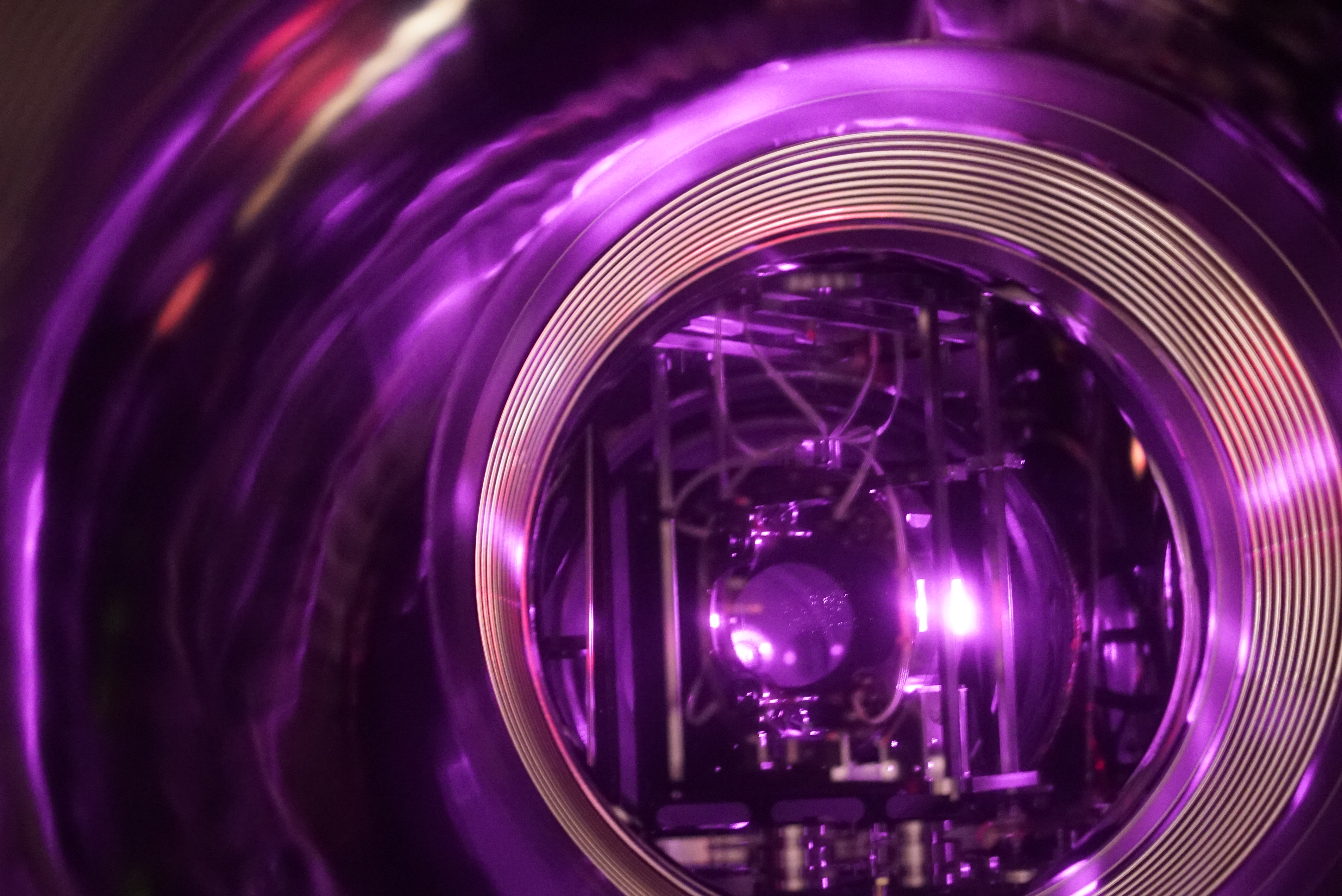
- Fig. 11: looked at PR2-BS from PR3.
- Fig. 12: looked at PR3 from the place between PR2-BS
- Fig. 13: looked at BS from the place between PR2-BS


