Ushiba, Hirata, D. Chen, Akutsu; following 29629.
Summary
Completed checking if the main beam would be clipped at apartures of the mid baffles around SR3, SR2, or SRM, and not that. Looked for the SRM "HR"-side reflection beam but not found, while the "AR"-side reflection beam might be seen (probably...?) We did not move any mid baffles around SR3, SR2, or SRM.
Details
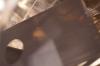
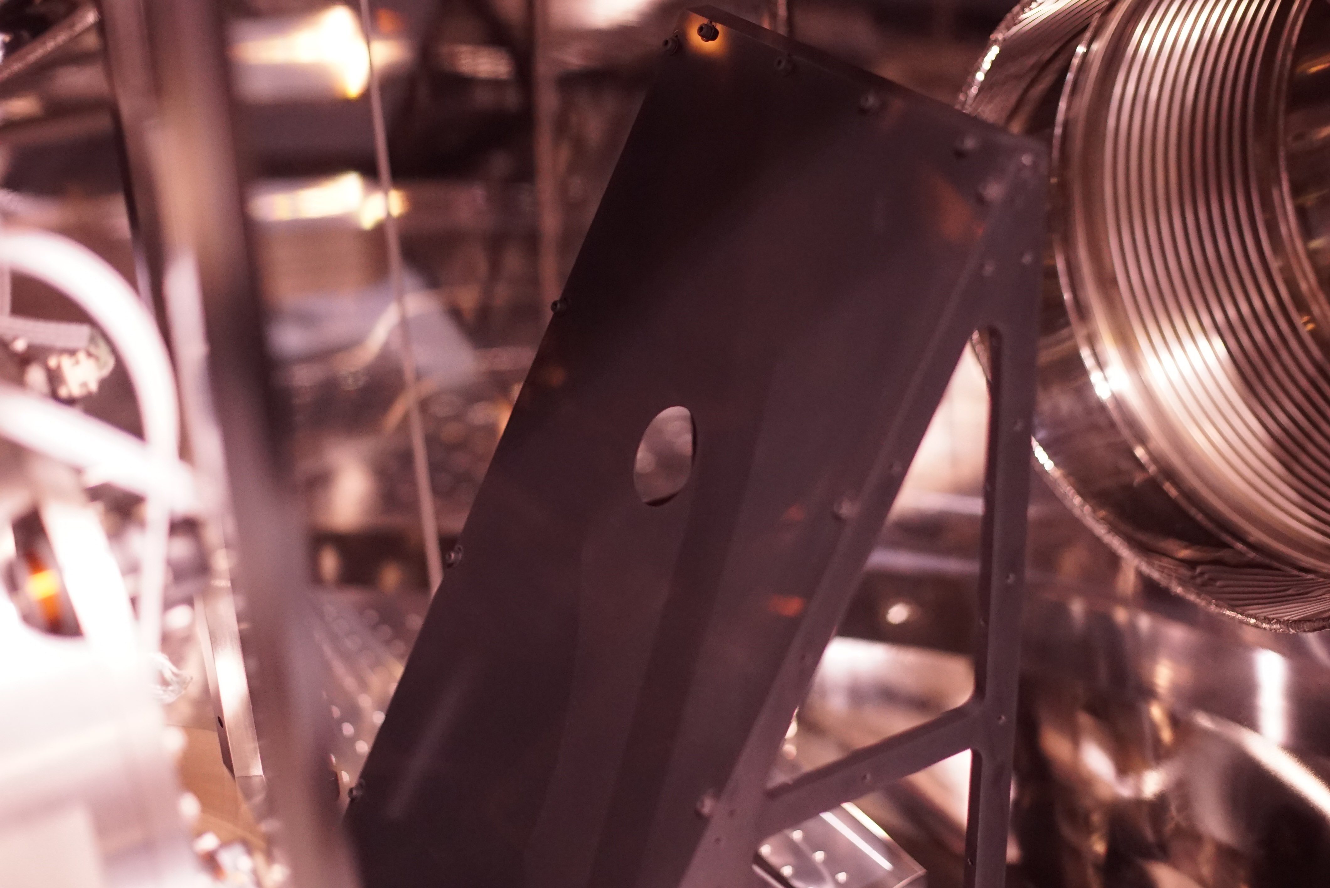
We checked carefully whether the beam clipping at the HR and AR mid baffles would happen or not around SR3, SR2, and SRM with the Miyakawa-san's camera. For SR3, no such clipping tendency were observed for the HR (Fig. 1) and AR (Fig. 2) mid baffles. We also tried to measure the gap between the main beam and the the aparture of the HR mid baffle. In my impression, there are relevant gap exsiting, although the current beam path is 5-6 mm off yaw from the noimnal one. Anyway, it is difficult to take some photos for these.
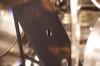
At SR2, we found (1) no severe clipping tendency at the HR mid baffle (Fig. 3) with the camera and sensor card, (2) no severe scattering tendnecy at the AR mid baffle, (3) there are some ghost beam spots near the HR mid aparture, and (4) the SR2 transmission IR beam would reach around the center of the invac steering mirror on the suspeded table.
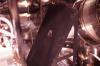
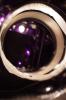
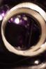
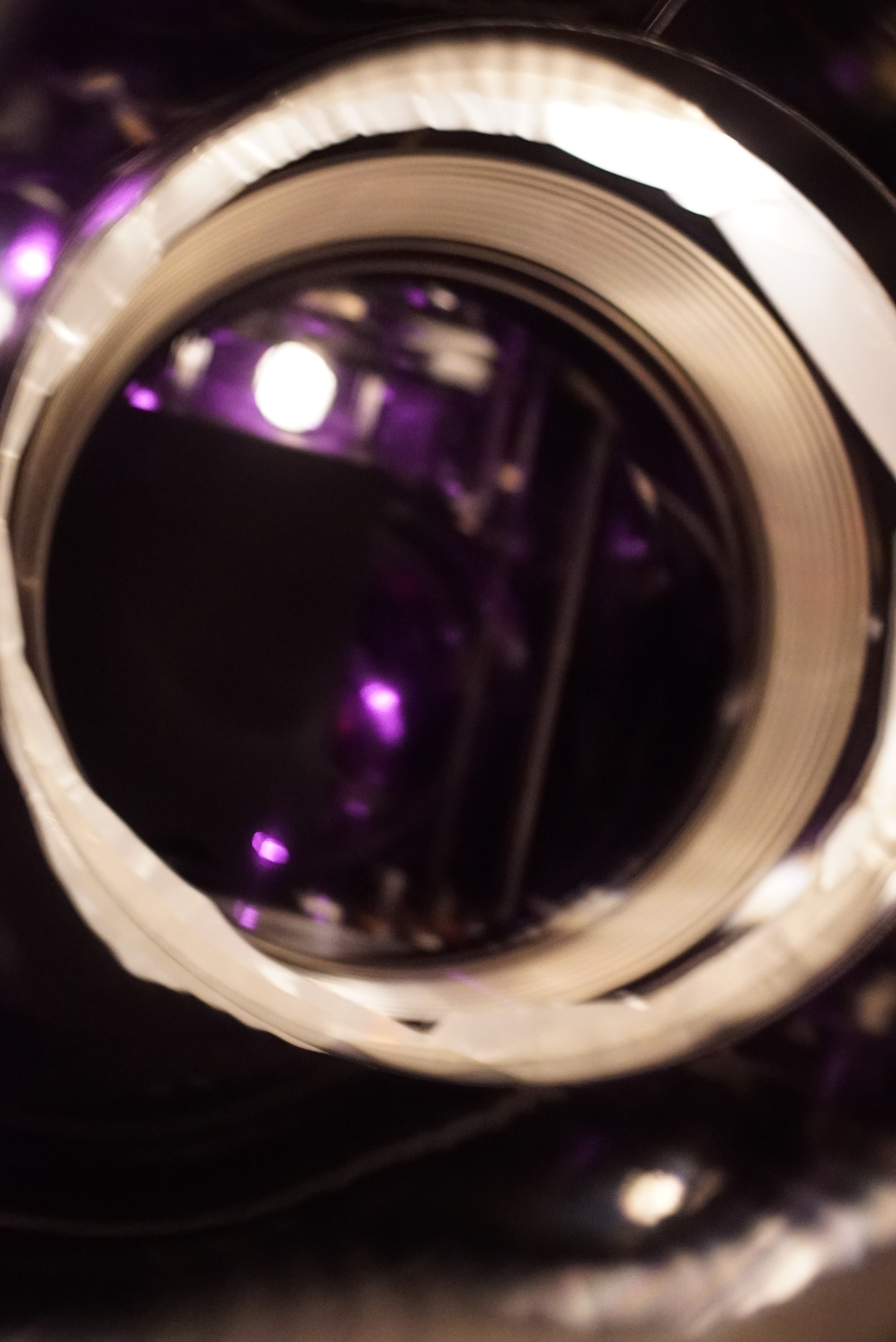
At SRM, we found (1) no severe clipping tendency at the HR (Fig. 4) mid baffle with the camera and the sensor card (the beam was passing the center of the aparture), (2) no severe clipping tendency at the AR (Fig. 5) mid baffle with camera and the sensor card (the beam was passing the center of the aparture), and (3) there was a beam spot --- a ghost beam spot from maybe SRM "AR" (see again Fig. 4, the upper left of the aparture). Here, SRM "AR" surface means the surface facing OMC side. Following yesterday, we tried to find a reflected beam from SRM "HR" (note that we are curretly using a transparent SRM with a certain RoC, so both the side was AR coated; see also 29635) but could not find it.
Discussion
Why we thought the found in Fig. 4 was from SRM "AR"? According to the specification (ITEM2 of JGW-T2415804), the thickness is about 9.5 mm and the material is a fused silica (AQ2 of Asahi Glass, refractive index at 1064 nm is n=1.44967) with 2 deg wedge angle. Because once we had done some RSE experiment after O3GK, let's assume the current ALIGNED state of SRM suspension would bring the 1st surface (or "HR") reflection beam from SRM mostly direct backward; and so, so far we could not see this ghost beam. To know how much the AR ghsot beam would shift, the following contributions should be taken into account. First, the travel in the material: this should be small as this "dummy" SRM is thin as already mentioned; about 9.5 mm thickness. Assuming the input beam is coming at 0 deg, it enters the AR surface with 2 deg incident angle, and so the transverse shift would (2 deg) * 9.5 mm = only 0.3 mm to reach the HR surface. Then, at the HR surface, ignoring the ROC, the incident angle from the fused silica side is 4 deg. With the Snell's law, the output angle should be n*(4deg) = 5.8 deg. From this surface to the HR mid baffle, the distance would be about 300 mm or so. So the displacement from the main input beam and this reflected ghost beam should be, on the HR mid baffle, 300mm * 5.8 deg = 30 mm or so. This is consistent value with the one observed in Fig. 4.
Others
We also found some IR shining spot when I saw inside the chamber with the camera; I quitely peeled off a part of aluminum foil at the BS chamber toward SR2, and inserted the camera to see the SR2 side. When turning off the IR main beam, some of them are still there, so they are of OSEMs, while some beam spots disappeared (before: Fig. 6 and after: Fig. 7). So they must be stray light field. So far we did not do (could not do) anything for them.

