Aoumi, Kamiizumi, Tomura (mine), Takano (remote)
Abstract
We investigated the oscillation of the common mode servos installed in ALS1 rack one by one. The servos oscillated around 28 MHz as we expected. We also found an extremely large 50MHz peak from Summing node, which seems to come from GrPDH X/Y servo.
We also confirmed that GND of the input signal of FIB X/Y servo is well isolated from GND of FIB X/Y servo (above 1MΩ), that is the reason why these two servo is not oscillated.
Detail
From the previous measurement we confirmed that the common mode servos installed in ALS1 rack (PLL X/Y, CARM, Summing node) oscillate at some MHz. To identify which servo oscillates at which frequency, today we investigated the situation of the oscillation one by one.
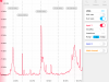
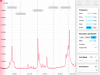
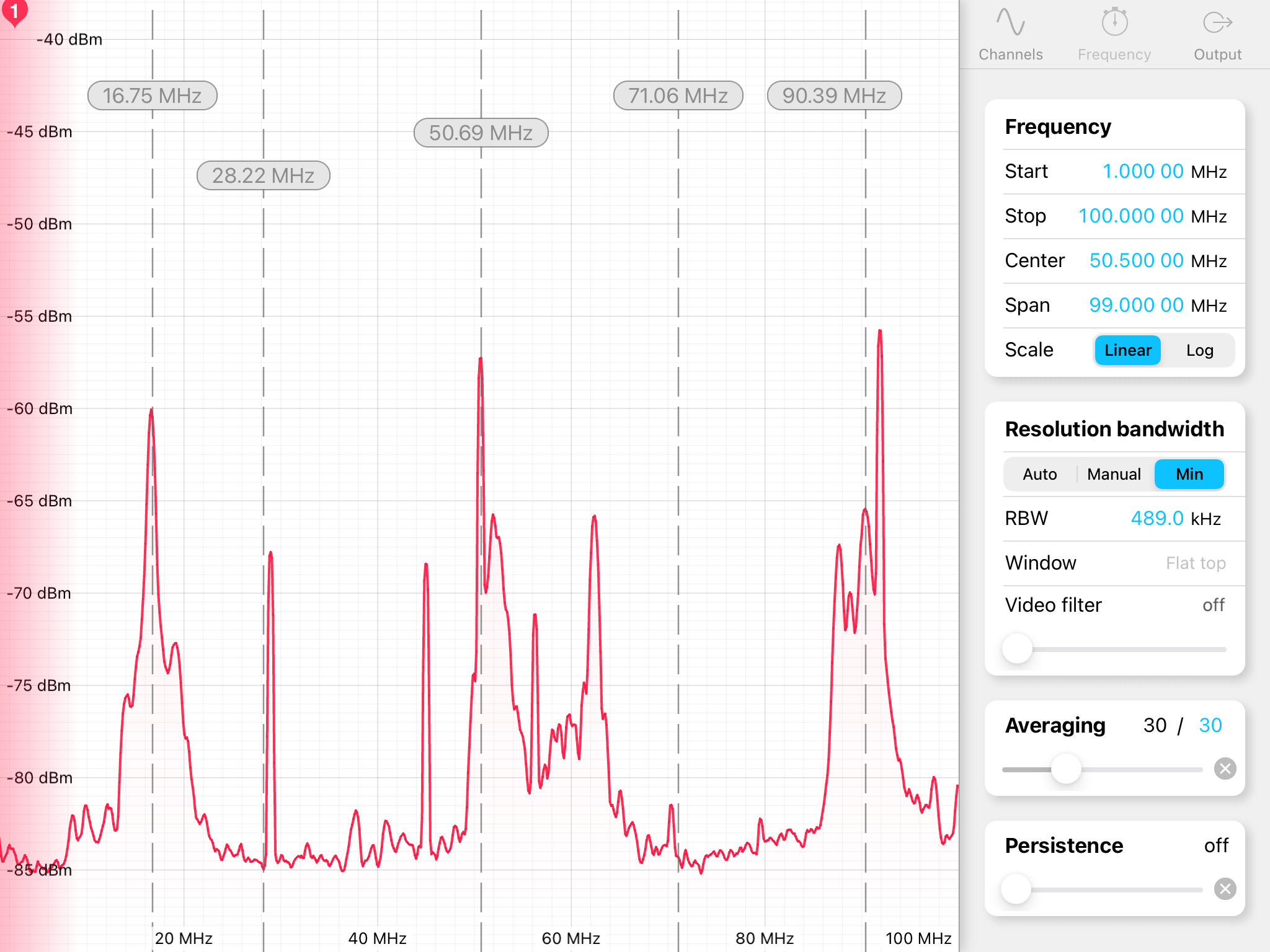
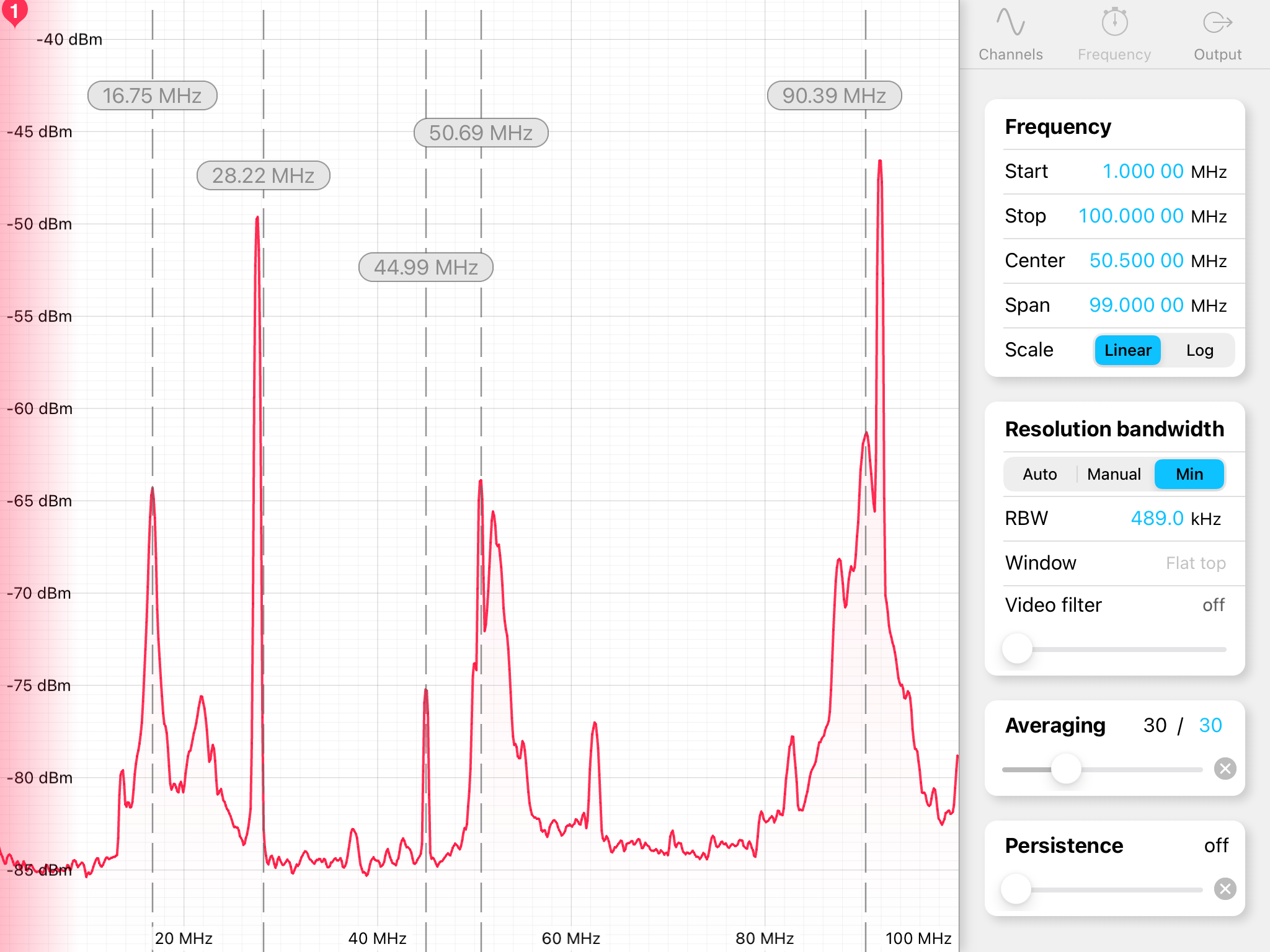
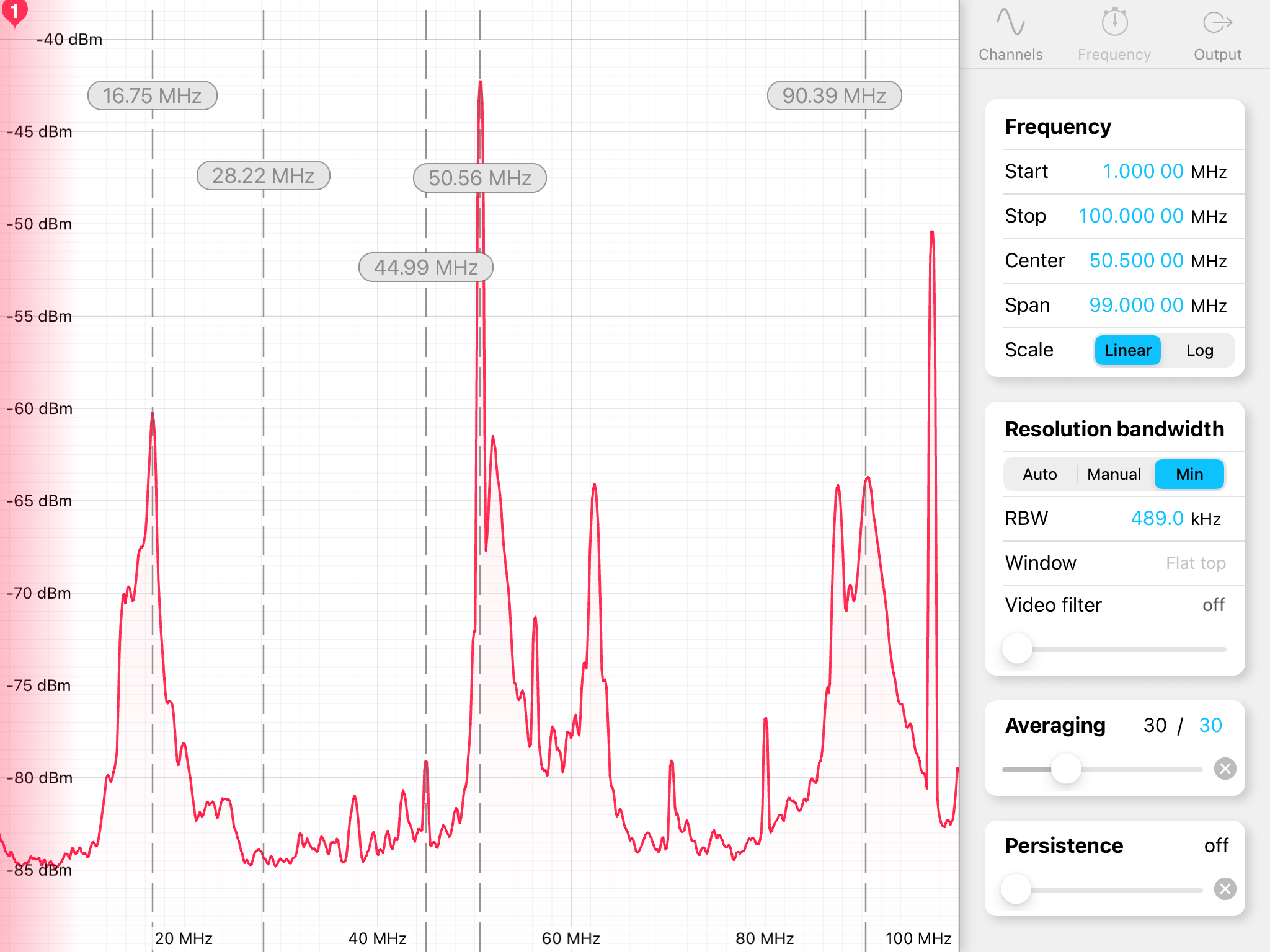
Figure1 shows the spectrum with all the servo installed in the rack turned on measured by the same way in the previous measurement. We saw oscillation peaks at 17 MHz and 28.MHz. After turned off all these servo, we saw the spectrum shown in Figure2.
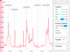
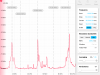
After that, we turned on each servo one by one. Figure3 and Figure4 show the spectra with PLL X turned on and PLL Y turned on, respectively. For PLL X a large peak exists at 28 MHz, which is likely to come from the oscillation of the servo. On the other hand, for PLL Y we ccouldn't see any peak around there. Then, we checked the length of the BNC cable between PFD and PLL X/Y servo, and found that the length is different between X and Y; 1m for PLL X and ~ 2.5m? for PLL Y (it was hard to confrim the actual length, but at least longer than 1m). Therefore, it seems that for PLL Y the length of the BNC cable is enough long not to oscillate.
Next, we chacked the signal from CARM servo and Summing node. FIgure5 shows the spectrum from CARM, and Figure6 is from Summing node. We found a large peak around 28 MHz, which seems to come from the oscillation due to the connection between Qmon of a I/Q demodulator and the servo. For Summing node no peak apeared around 28MHz, but an extremely large peak existed at 50 MHz. It was also confirmed that even if we turned off the power of Summing node this peak still exsists. Therefore, we suspected that this peak comes from Gr PDH servos.
We move on to Gr PHD X/Y servos. We measured the signal around SLOW OUT of each servo, which goes to the inputs of Summing node. The measured spectra are shown in Figure7 for PDHX and Figure8 for PDHY, respectively. It is obvious that there exists a peak at 50 MHz, and this implies that the peak in Summing node comes from Gr PDHX or Gr PDHY. But we are not sure of the source of the peak.
Finally, we checked the GND level of the input of FIB X/Y servos, which don't oscillate from the previous measurement. We measured the resistance between GND of the input BNC cable and GND of OUT2. The results are shown in the table below:
| Servo | IN1 | IN2 |
| FIB X | 1.6 MΩ | 1.6 MΩ |
| FIB Y | 2 MΩ | 1.6 MΩ |
From the results it is clear that GND level of the input of these servos are well isolated from that of the servos, and that is the reason why these two servo don't oscillate.
Conclusion
We almost understand the condition of the oscillation; the common mode servo oscillates if the one of the input is close to GND level of the servo (≈ single ended signal from a circuit with the common GND level) and the cable length is enough short (<1 or 2m?).
On the other hand, we found a large peak at 50MHz existing in Gr PDH X/Y and Summing node. We don't know its source and should investigate it for future.

