Aoumi, Kamiizumi, Tomura, Takano
Abstract
We checked whether all the common mode servos installed in the rack are oscillating or not, and found that 6 of 9 servos are oscillating.
Background
We noticed a strange MHz peak from GrPDHY servo (klog 29446), and first thought that there is something wrong in this specific servo. However, from the investigation of AEL specialists it was found that when the negative input of the differential driver of the common mode servo is connected to GND, the opamp used in this receiver starts oscillating at some MHz. The oscillating frequency depends on the cable connecting to the input of the servo. Unfortunately, the input signals of all the most comon mode servo already installed are such signals, and therefore it is possible for all the common mode servo to oscillate at some MHz frequency.
Works
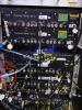
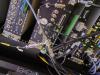
We measured the radiated signal from the servos with handmade antennas. The target servos are:
- LSC0 rack: GrPDHX, GrPDHY
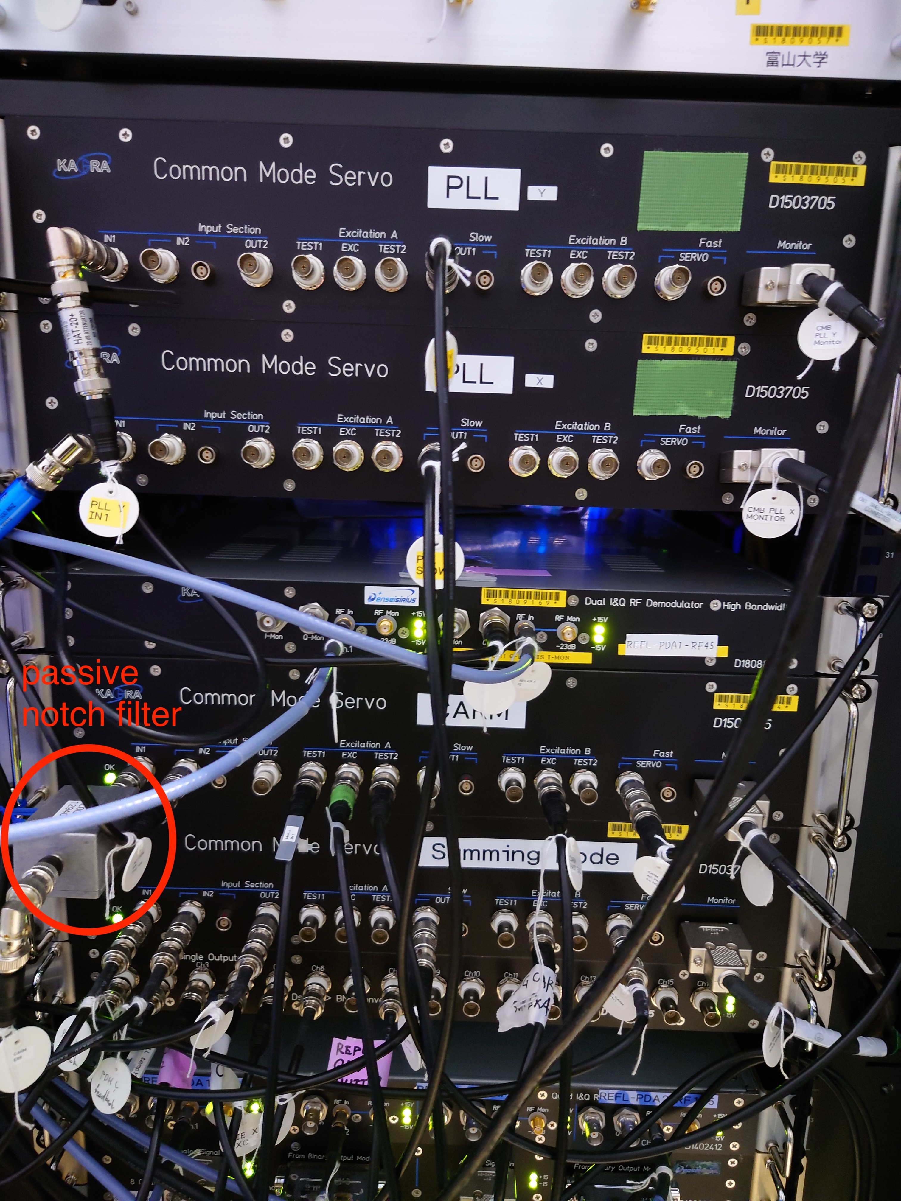
- ALS1 rack: PLLX, PLLY, Summing node, CARM
- ALS0 rack: FIBX, FIBY
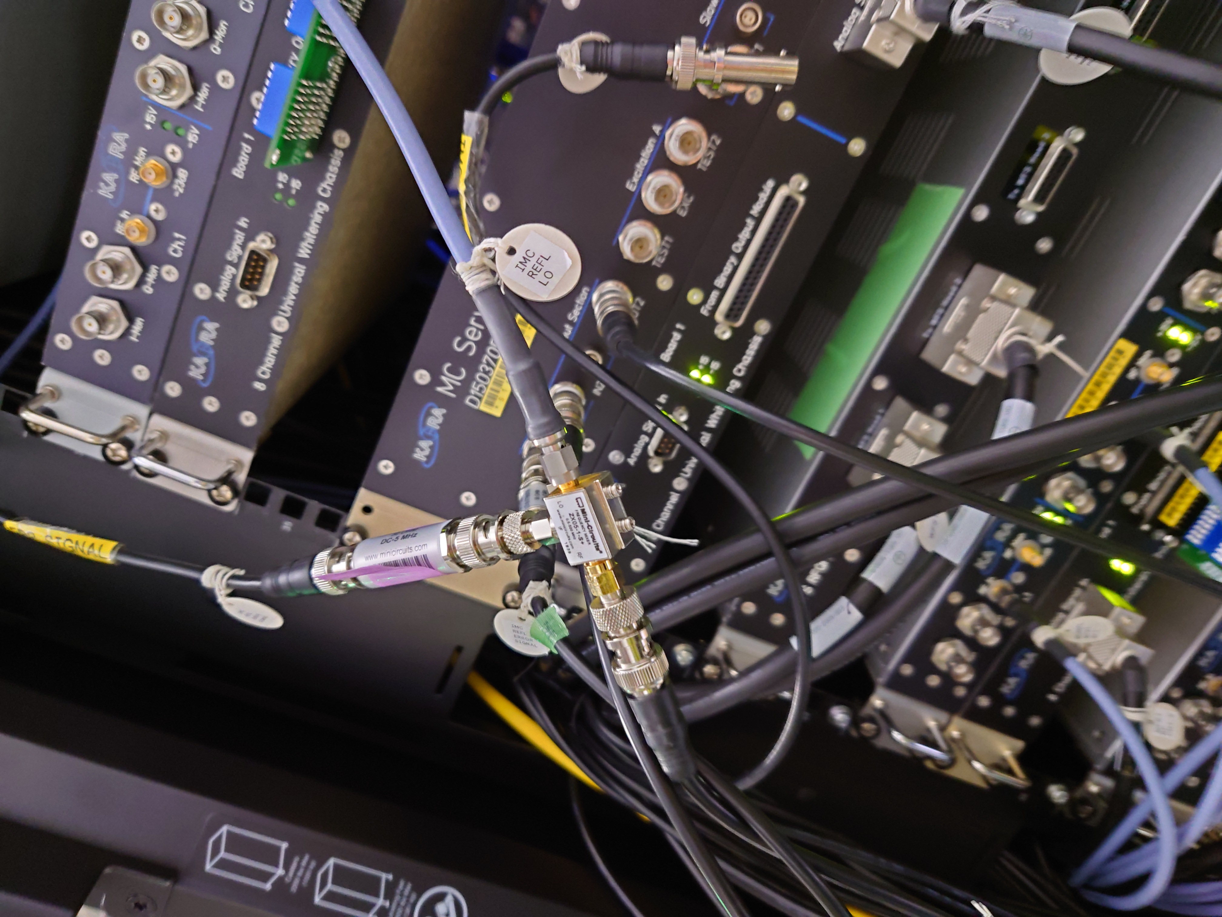
- IOO0 rack: IMC
LSC0 rack
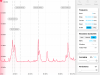
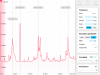
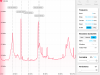
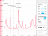
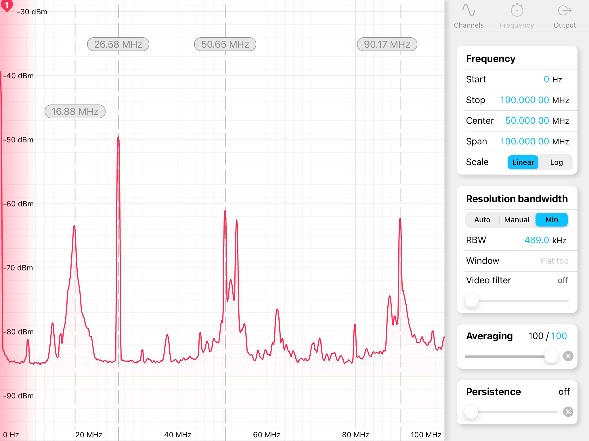
We confirmed that GrPDHX oscillates at 26.6 MHz and GrPDHY at 19.2 MHz. Figure1 and Figure2 are the signals close to GrPDHY and GrPDHX, respectively. If we disconnect the cable between each servo and the demodulator, these peaks dissapeared. Even when we turned off the power of GrPDHY and remove all the cables attached to it, we saw the 26.6 MHz oscillation if GrPHDX servo was connected to the demodulator. Therefore, the oscillation signal coupled to other circuits via the rack mounted to these circuits.
ALS1 rack
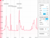
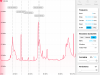
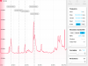
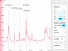
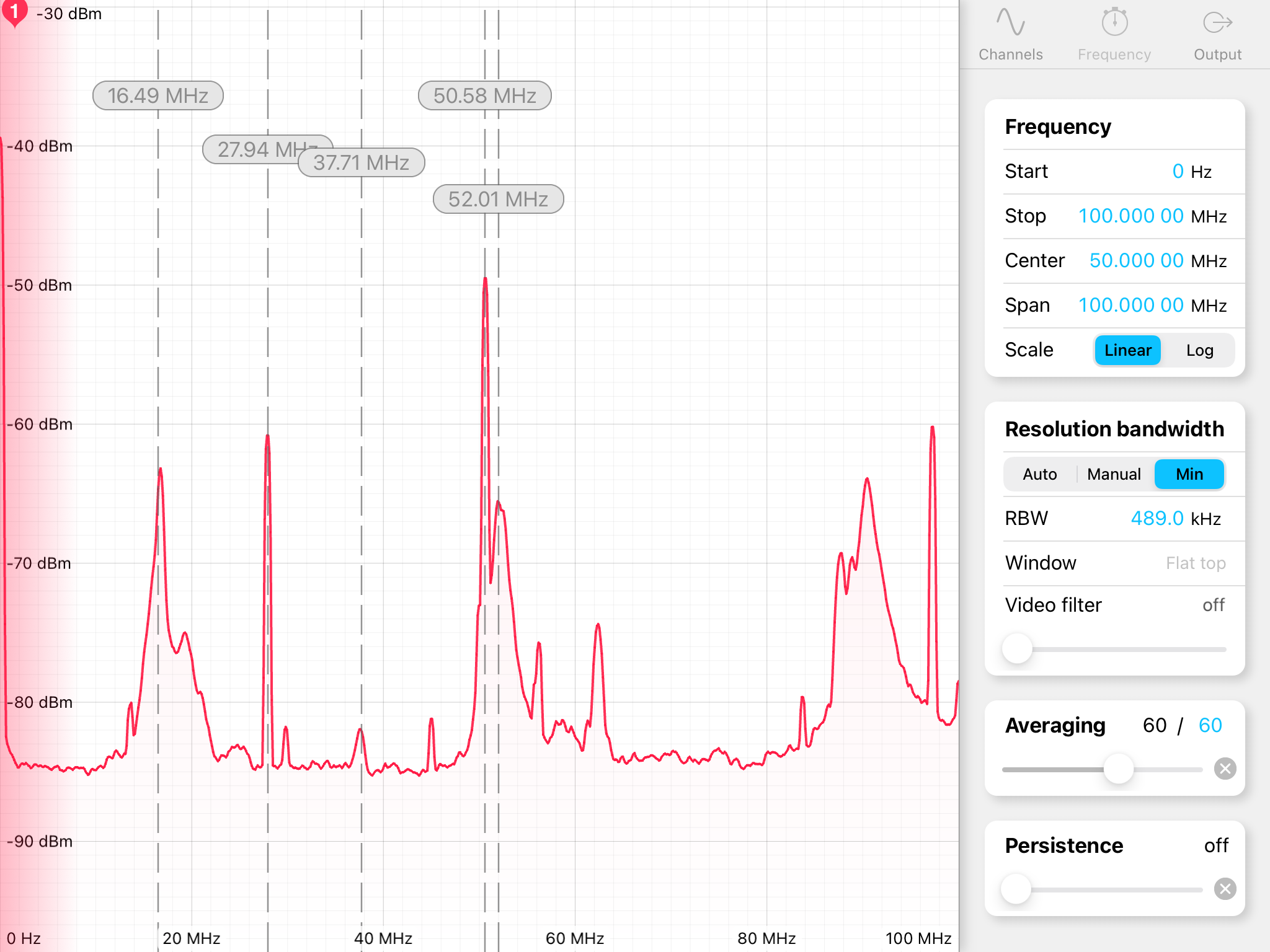
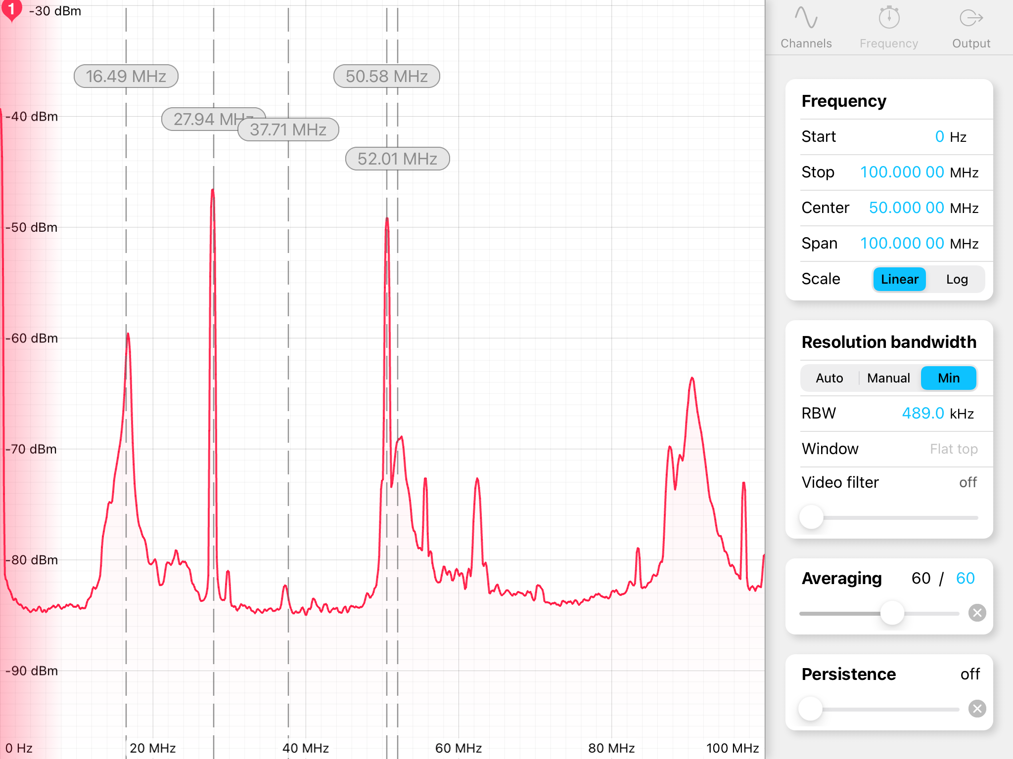
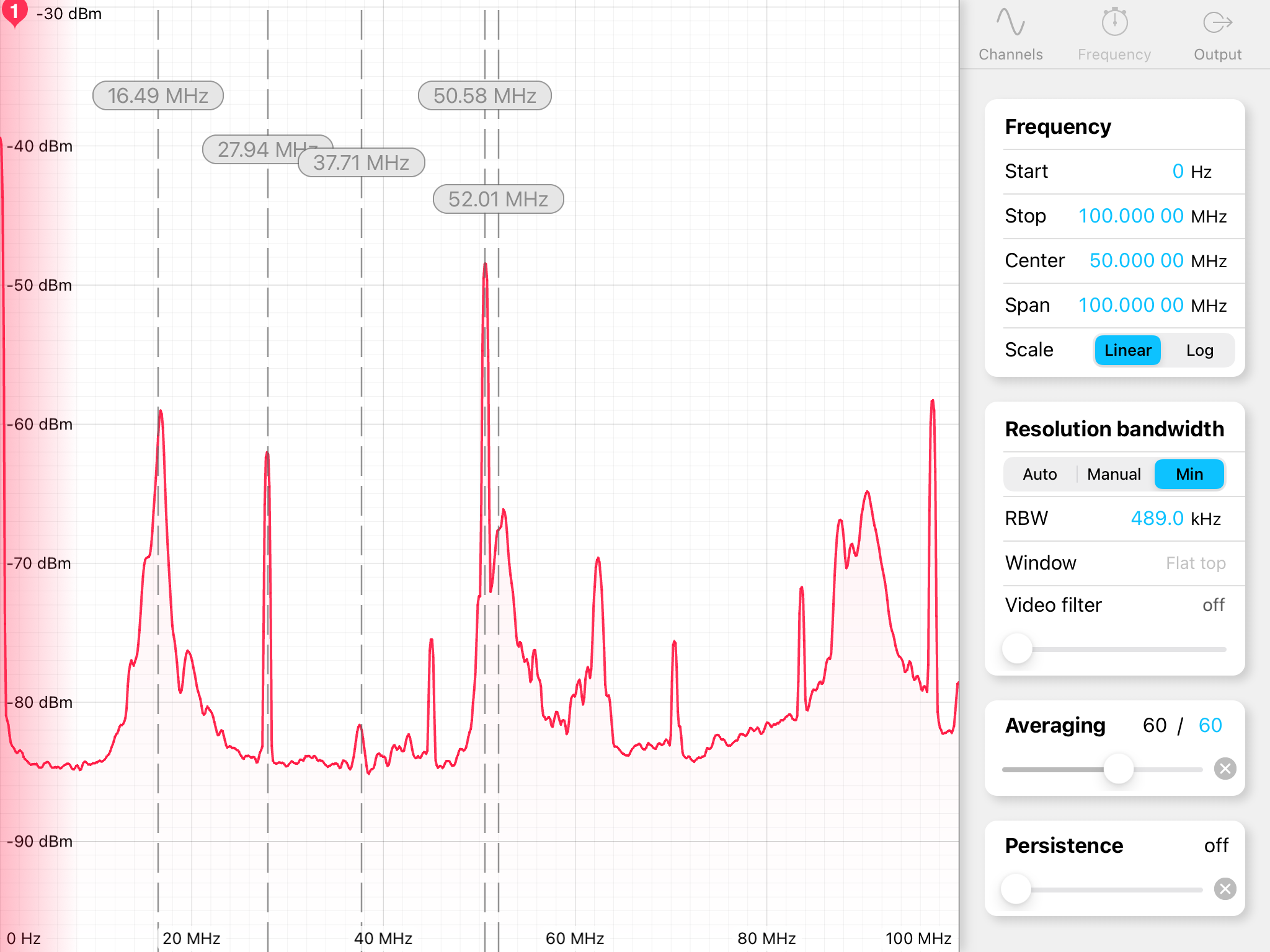
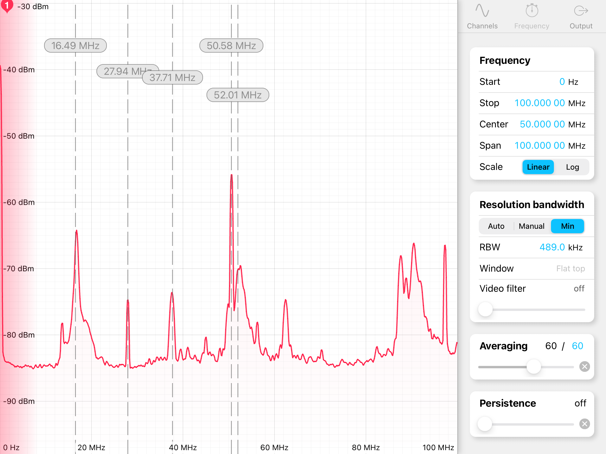
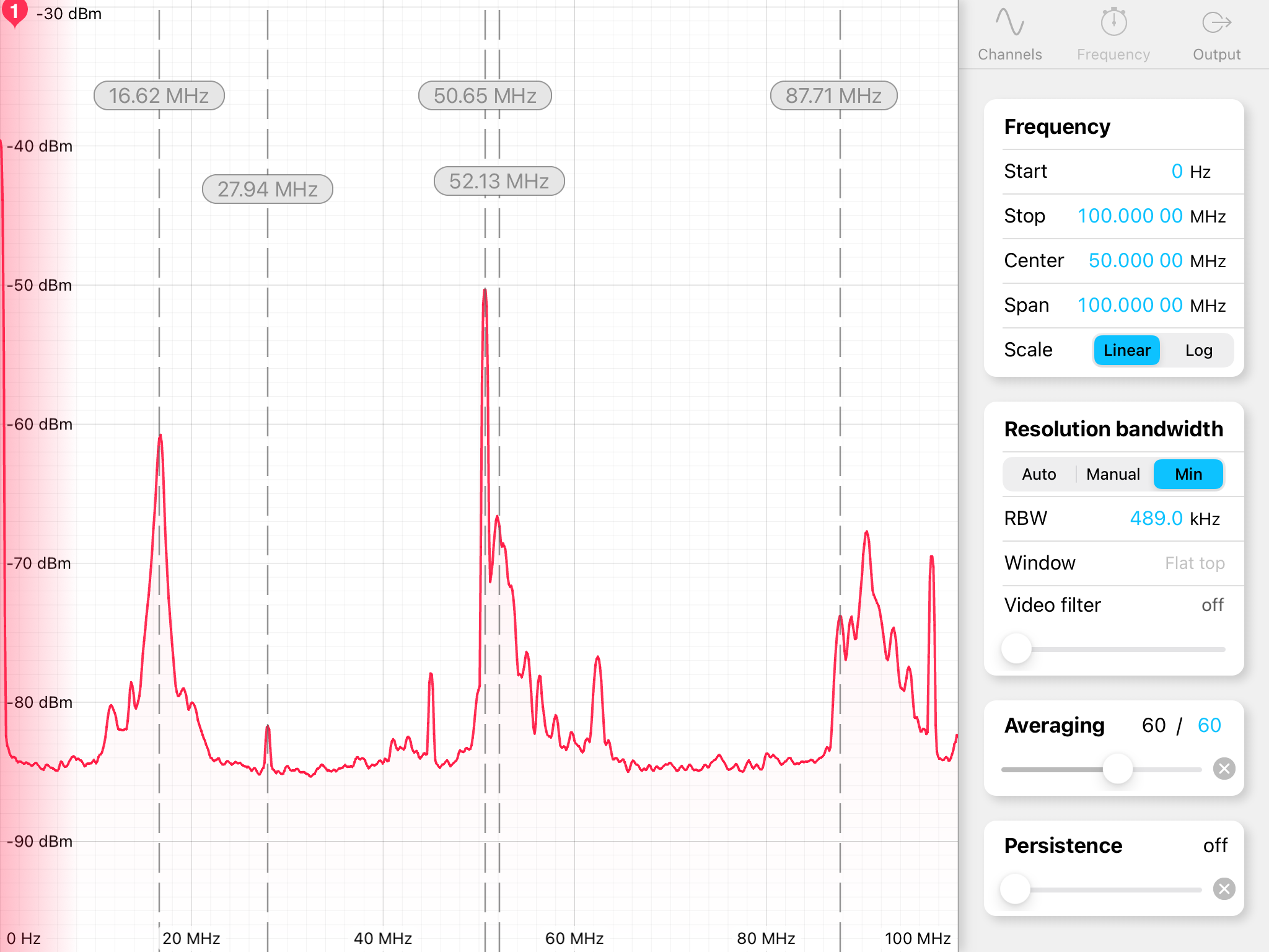
Next we checked the oscillation signal around the common mode servos installed in ALS1 rack. Figure3-Figure6 are the spectra measured around PLLX, PLLY, CARM, and Summing node. We found two dominant peaks, 16.5 MHz and 27.9 MHz. It seems that all the servos installed in ALS1 rack oscillates due to the input signal.
ALS0 rack
We moved on to ALS0 rack. Figure7 and Figure8 show the spectra around FIBX and FIBY servo. It seems that these circuits are not oscillated. This may be because the input signal to FIBX and FIBY are from DC PDs in PSL room, which GND is floated from the rack.
IOO0 rack
Finally we checked the radiated signal around IMC servo, and no oscillation peak was detected as shown in Figure9. We are not sure why this servo doesn't oscillate.
Remarks
Considering the oscillating frequency and the length of the cable connected to the input of the servo, it seems that with a 1m BNC cable the oscillation frequency is aroun 26 - 28 MHz, and with a 2m BNC cable the servo oscillates around 17 MHz.
Conclusion
We confirmed that 6 of 9 common mode servos oscillate at some MHz frequency. It is also found that the oscillation affects the other circuits on the same rack. To reduce the MHz noise in CARM servo, we have to solve the oscillation problem for all the 4 servo installed in ALS1 rack.
Future plan
For GrPDHX/Y and PLLX/Y we use a monitor signal as the input of the common mode servos, and these signals are single ended. If we replace them with differential ended signals, the oscillation may stop. One solution is to make use of the differential signals of the back plane of the demodulator/phase frequency discriminator, which is now connect to AA chassis.
