Aso, Ikeda, Hirata, Takano, Akutsu; following 29261.
Summary
Confirmed the aligned light beam POP_FORWARD reached two QPDs on the POP table, but mostly clipped at a steering mirror on the POP table. So not yet centered to these QPDs. The work is still on the way.
Details
Yesterday we tweaked IMMT1 and 2 with their oplev setpoint in yaw to their limits. So, we were worried if the actual beam might be off-centered at IMMT2. So, we started with checking this. Before that, we called PROVIDING_STABLE_LIGHT to IO Guadian to make IMC with LSC and ASC. In addition, we also set IMC ASC gain to zero (following Ushiba-kun's suggestion) tentatively from MEDM so that we were able to walk across the light beam to IMMT1T without disturbing the aligned IMC. Then, we found that the spot on IMMT2 was seemingly mis-centered somehow (difficult to see it due to the fact that it is located in the deep of the chamber and the surface is protected with the black shield). So, we re-considered our plan. At this point, the new plan was to (1) reset the setpoint values of IMMT1 and 2 to the values before yesterday, (2) check the IMMT2 centering, and if not good, adjust with IMMT1 setpoint, (3) align IMMT2 to center the spot on PR2 with setpoint, and (4) adjust PRM centering with its traverser.
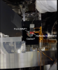
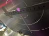
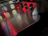
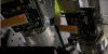
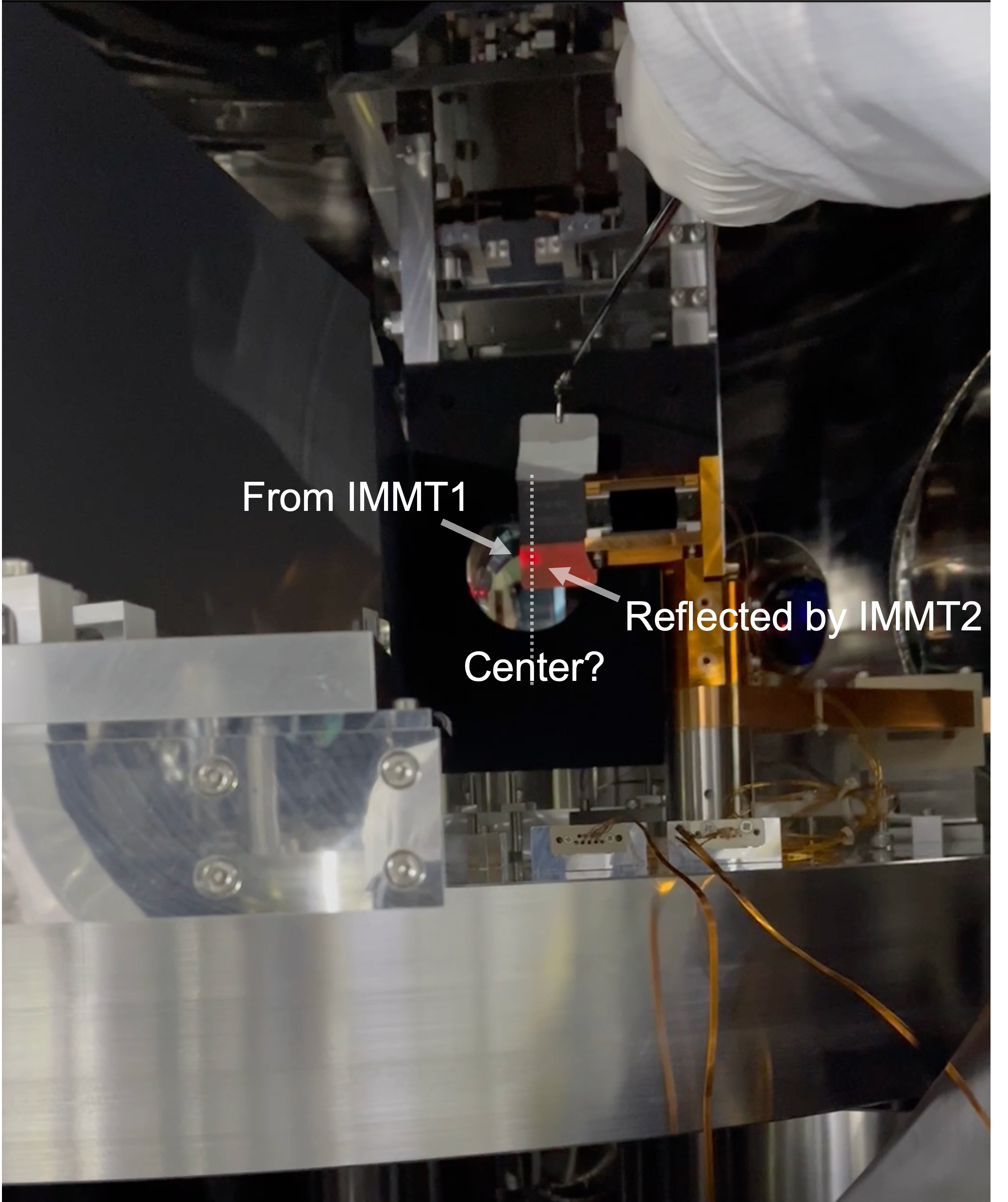
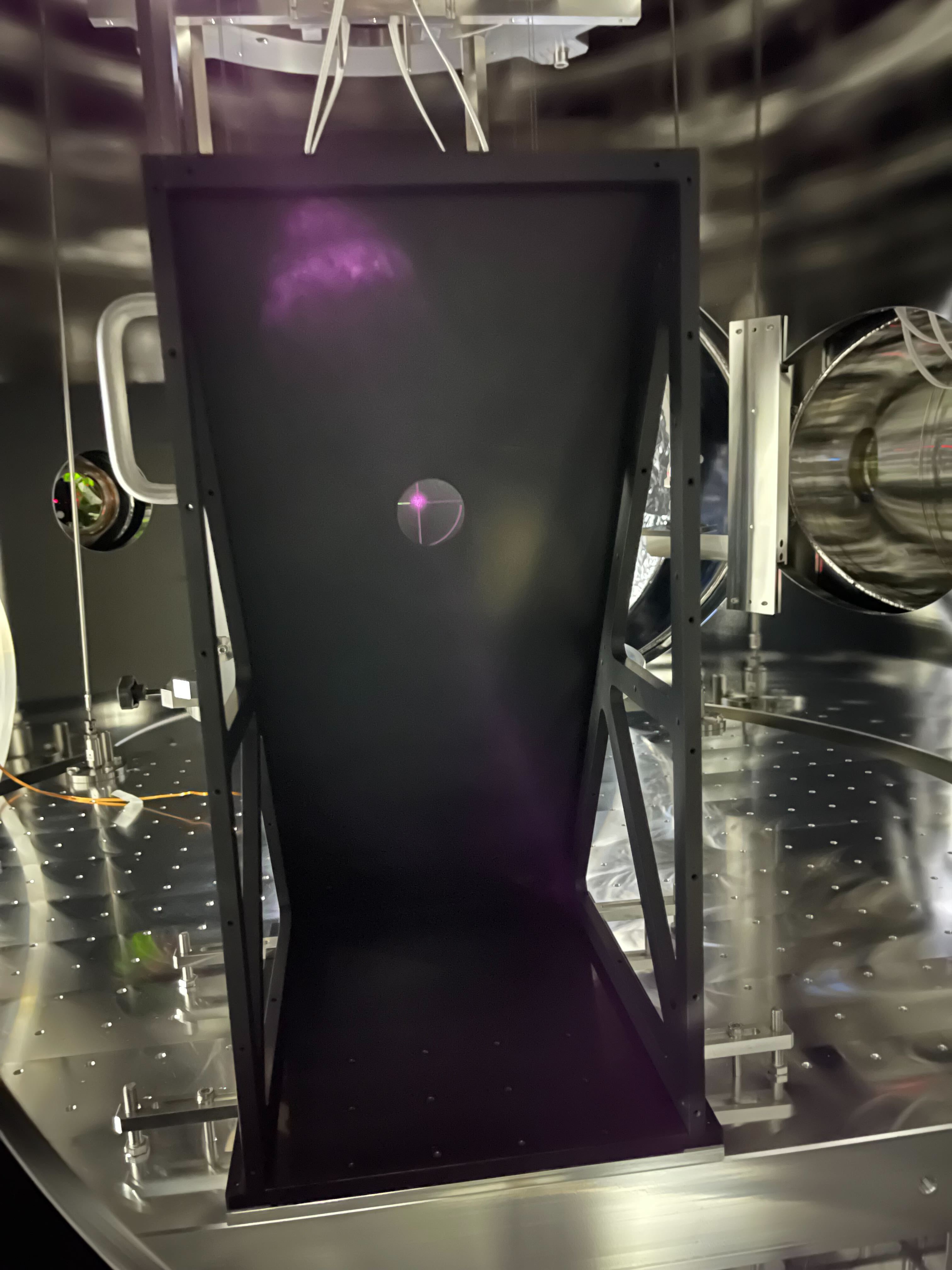
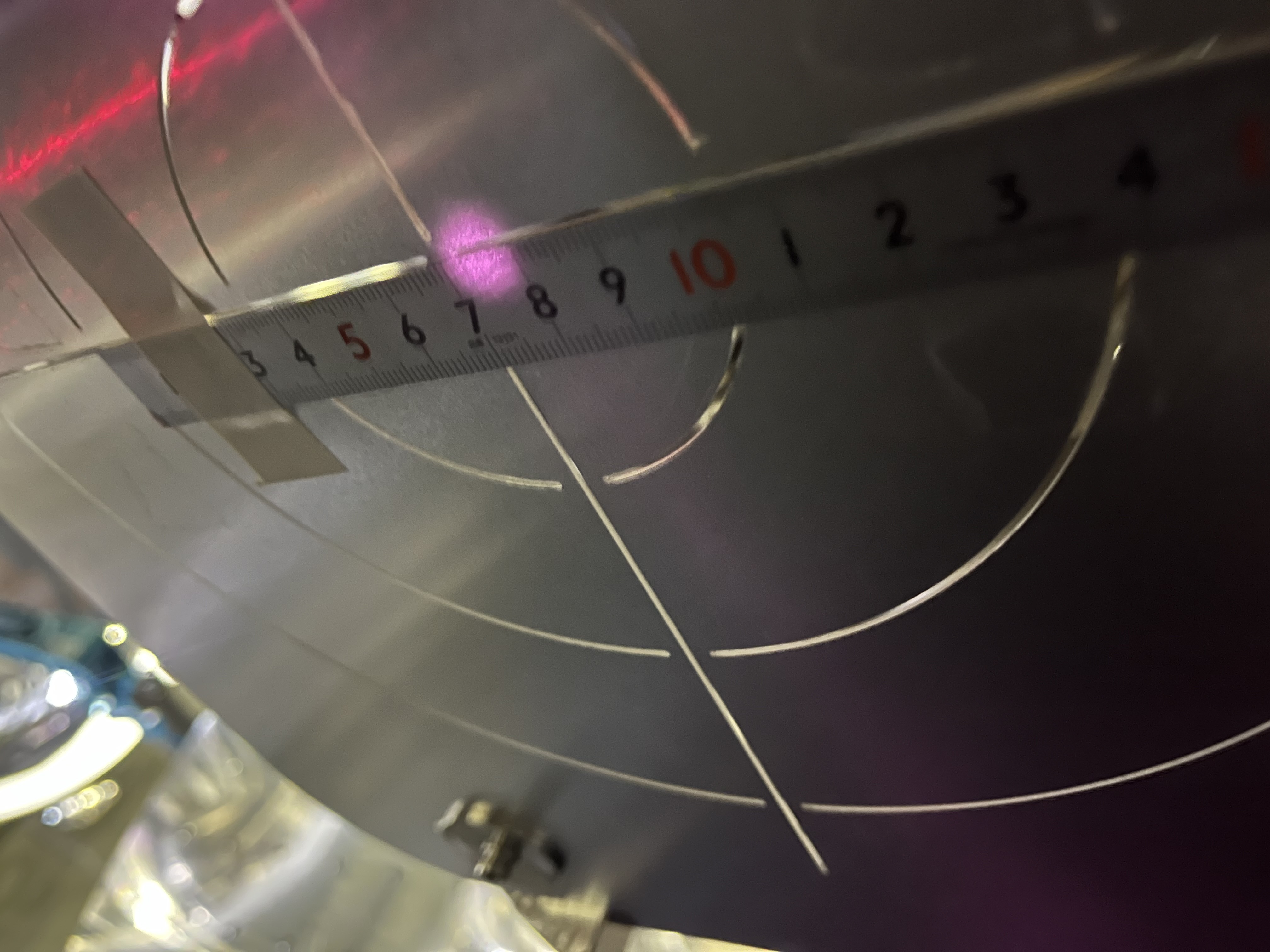
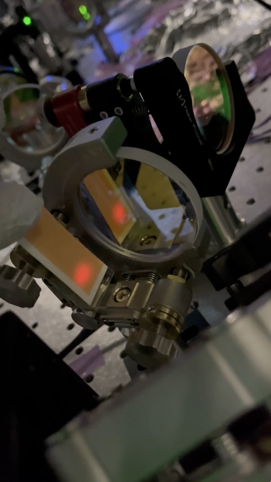
When reset IMMT1 setpoint, the beam centering at IMMT2 seemed ok (Fig. 1) , so we simply left the IMMT1 setpoint as reset value. Then, we tweaked IMMT2 to bring the beam spot at the center of PR2 (precisely, its HR target); Fig. 2. With this situation, we checked the beam spot postion at PRM (both at AR (Fig. 3) and HR (Fig. 4) with the relevant targets; these AR and HR spot locations were almost the same), and it was 5-mm off-centered in the minus Y direction.
5-mm would be too large for the PRM traverser to move. The demerit of using the traverser are (1) the small movable limit itself as already mentioned, (2) we need to adjust oplevs otherwise we would lose ALIGNED state of PRM (ALIGNED state would be useful to control a suspension with its setpoint values), (3) even though "ALIGNED" can be obtained, this would not mean the beam reflected at PRM could reach REFL, and (4) at any rate, PRM mid baffles do not follow the move of the main suspension chain of PRM. On the other hand, considering the RoC of PRM is ~460 m (kagra wiki), 5-mm off center might be acceptable or easily to be compansated.
So, we determined to modify the original plan mentioned above: (4) -> not adjust PRM traverser, but adjust mid baffles for PRM later.
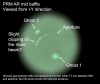
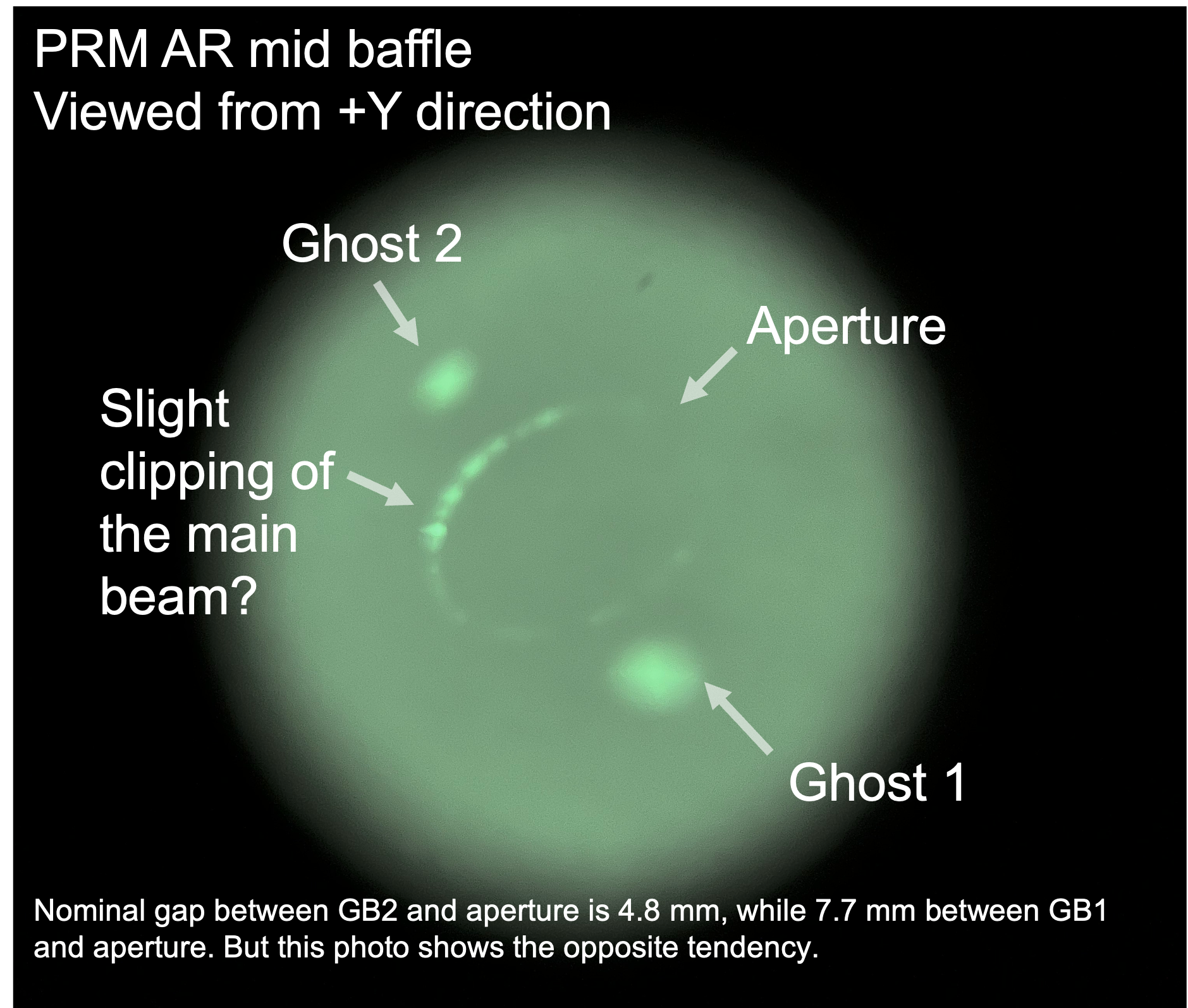
The PRM AR mid baffle seemingly caught two (known) ghost beams from PRM already. In this sense, this mid baffle would be also ok. But in fact, looking at the aperture of the PRM AR mid baffle, the aperture edge seemed shining with IR (Fig. 5; taken from a location between IFI and IMM with the Miyakawa-san's IR camera; two ghost beam spots at IMMT1's shield can be also seen, and they may come from IFI...). This shining might be due to the main beam's slight clipping. JGW-T1910659-v2 shows where these ghost beams and main beam would come at PRM AR mid baffle, and from these nomial locations, it would not be strage at all that this clipping might happen in the current situation: the main beam is shifted with respect to the aperture in the minux Y direction about 5 mm, while this document says the 2.8 sigma radius of this main beam should be nominally 4.8 mm away from the edge. So we will adjust the AR (and HR for balancing?) mid baffle position later. See also Fig. 6; also compare with 20797 and 21654.
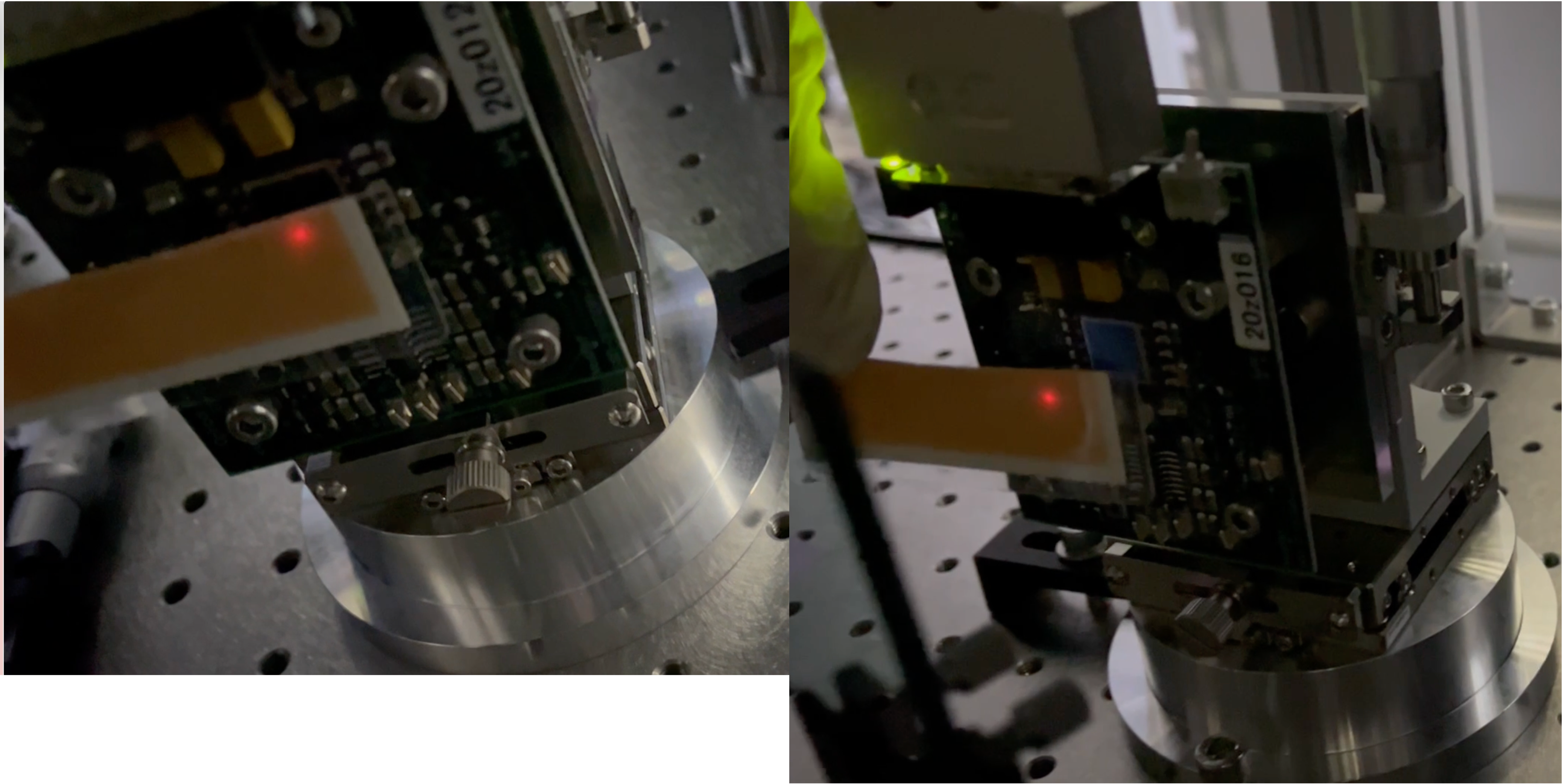
Anyway, apart from the slight clipping at this PRM AR mid baffle, the main beam would be well aligned. Then, we detached the duct connecting the POP table and PR2 chamber to see the PR2 transmission IR beam, or POP_FORWARD. Fortunately we confirmed that this beam was somehow reaching relevant two QPDs (Fig. 7). We also confirmed this with QPDs SUM count variation. But we also found that this beam was 90%-ly clipped at a steering mirror just after the periscope (Fig. 8). It seemed no simple way to resolve this clipping...
Note
- We confirmed that the beam spot on PR2 varied (more than 1 mm? anyway it was apparently obvious) depending on the PRM state PAY_FLOAT or ALIGNED. Be careful when you repeat this kind of initial alignment again. I recommend to do this kind of careful alignment together with more than one interferometer optical experts, otherwise you may easily forget this and saddly your alignment would be insane.
- The way "setting IMC ASC gain zero" should be done just before such a work starts that someone would pass across the light beam to IMMT1T, maybe; otherwise, as ASC gain is zero, the alignment of IMC may become worse in the long term. By the way, we firstly did the other way but it failed: firstly we just turned on signal hold switches only for the feedback signals from IMMT1T to pitch and yaw matrices, as we thought there might not any integrators in these feedback paths. But maybe we mis-understood something; every time IMC lost lock within a few minutes.


