Reports 1-1 of 1 Clear search Modify search
AEL (General)
tomonobu.tomura - 21:30 Friday 05 April 2024 (29112) Print this report
Gain jump of the IMC Common Mode Servo

[YamaT, Kamiizumi, Tomura]


Summary

We checked what happens to the output when we change the gain from 16dB to 15dB with the IMC Common Mode Servo (S1605810).

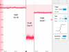
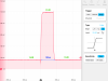
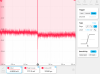
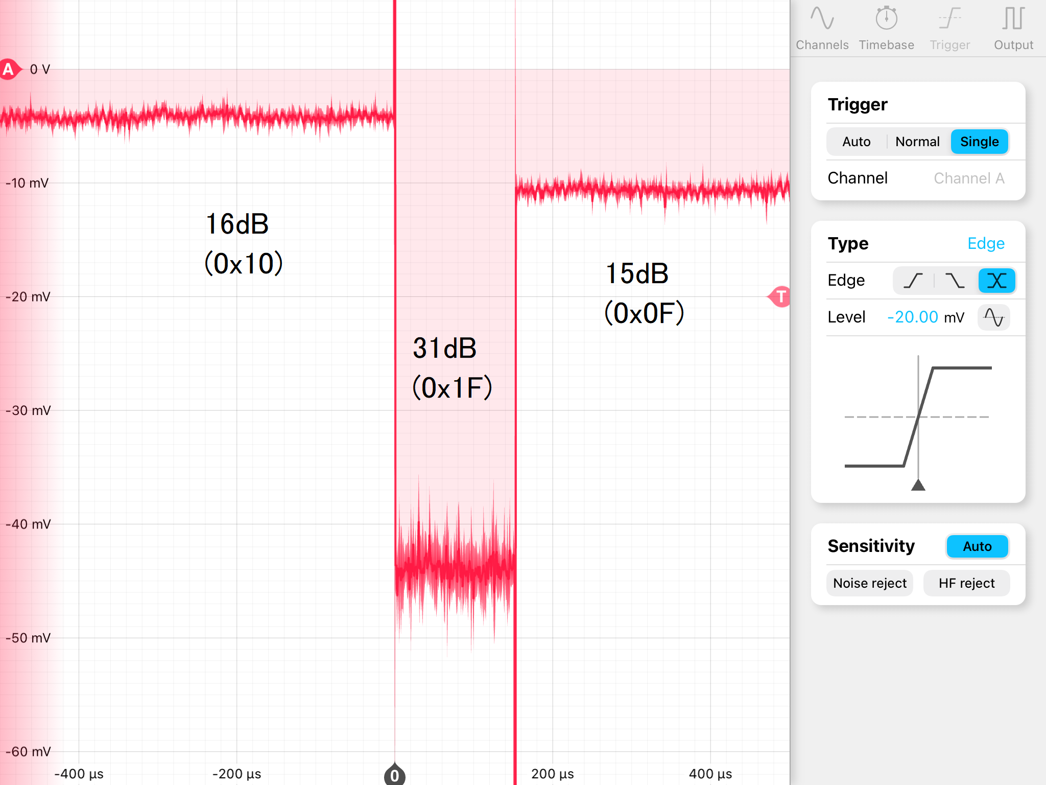
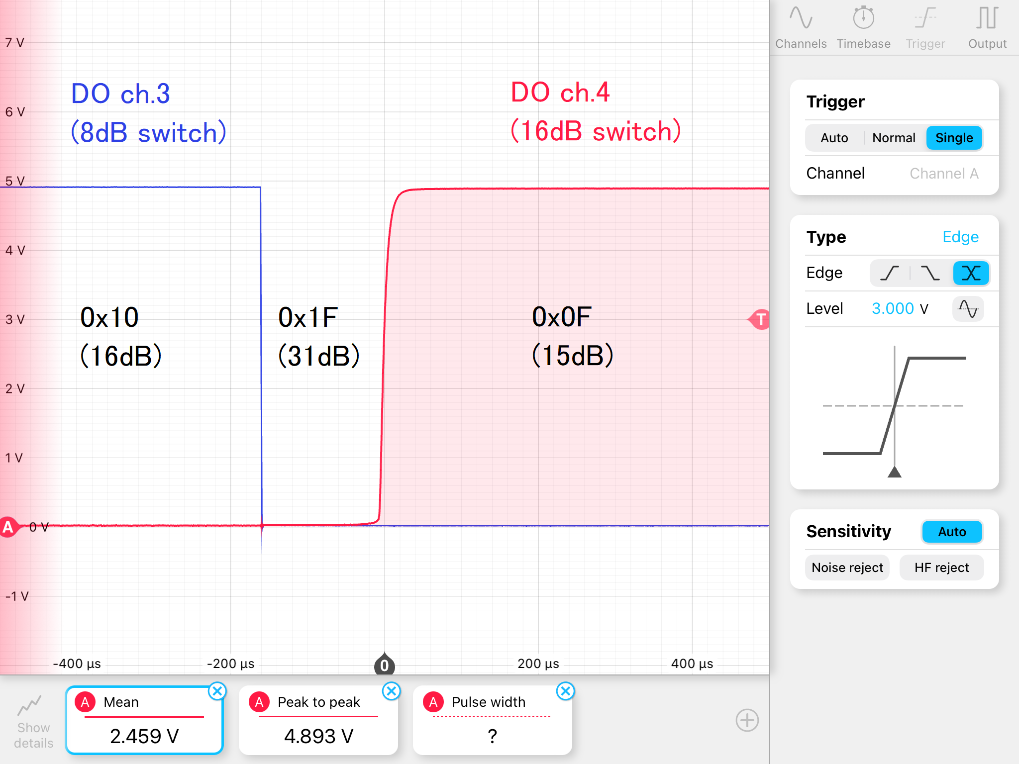
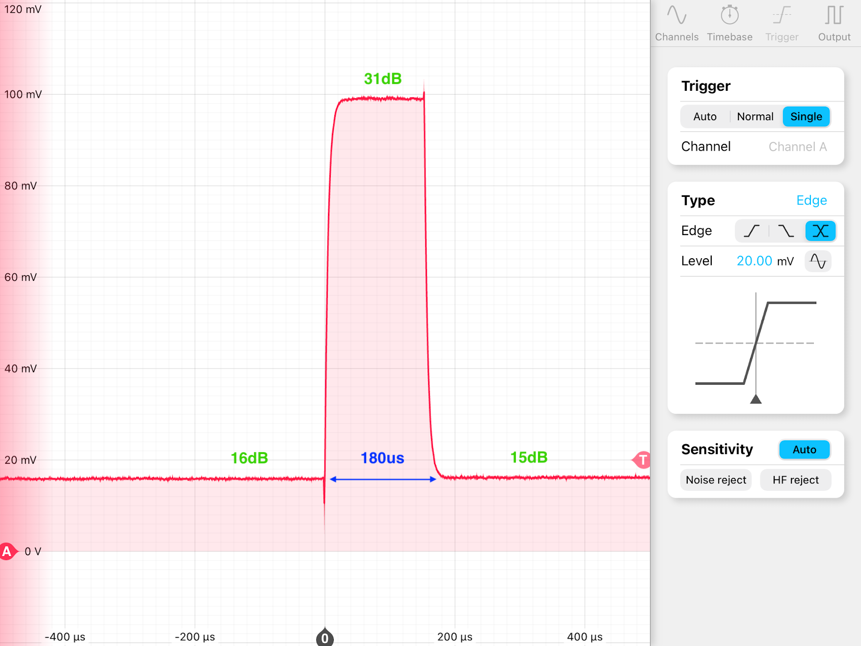
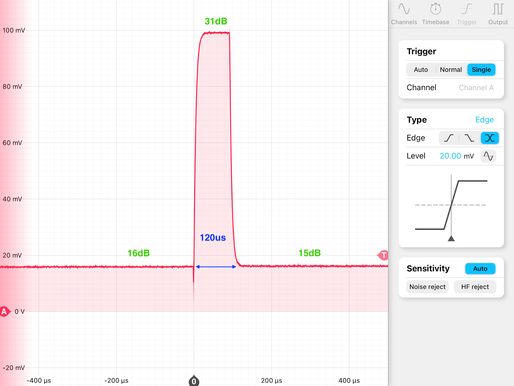
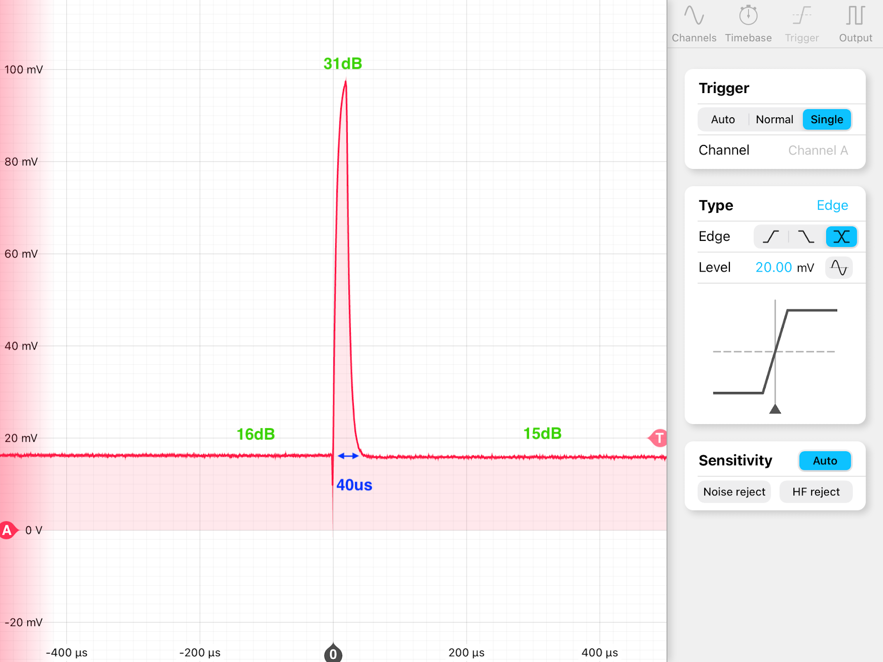
1st figure shows the output from OUT2.  It shows that the gain first changed to 31dB for ~150us, then became 15dB.

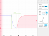
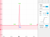
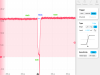
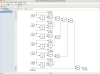
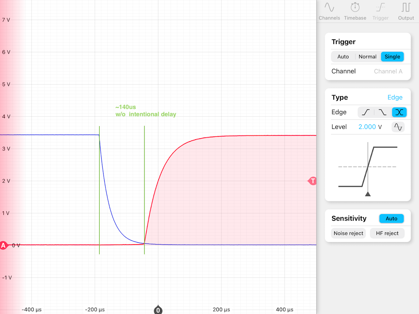
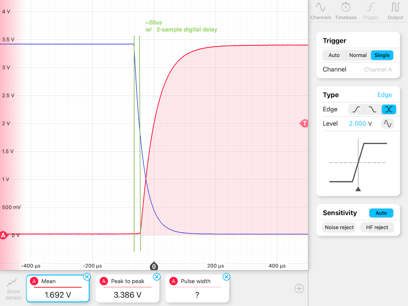
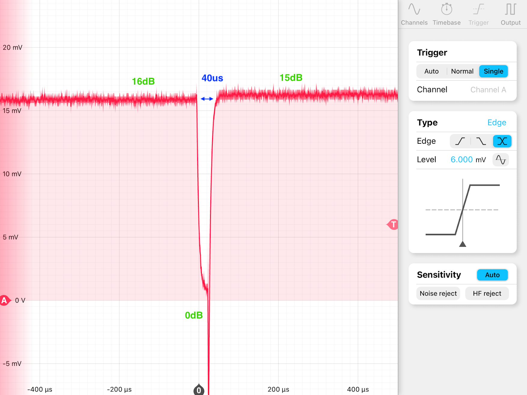
This is due to the timing difference of the digital outputs between 1->0 and 0->1.  (2nd figure)


Detail

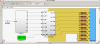
As reported in klog No.26657, Common Mode Servo has different offsets for the different gain settings.

AEL group was asked to adjust the offsets for 16dB and 15dB to be the same for the IMC CM servo, then found a strange behavior while testing it with the DGS test bench.

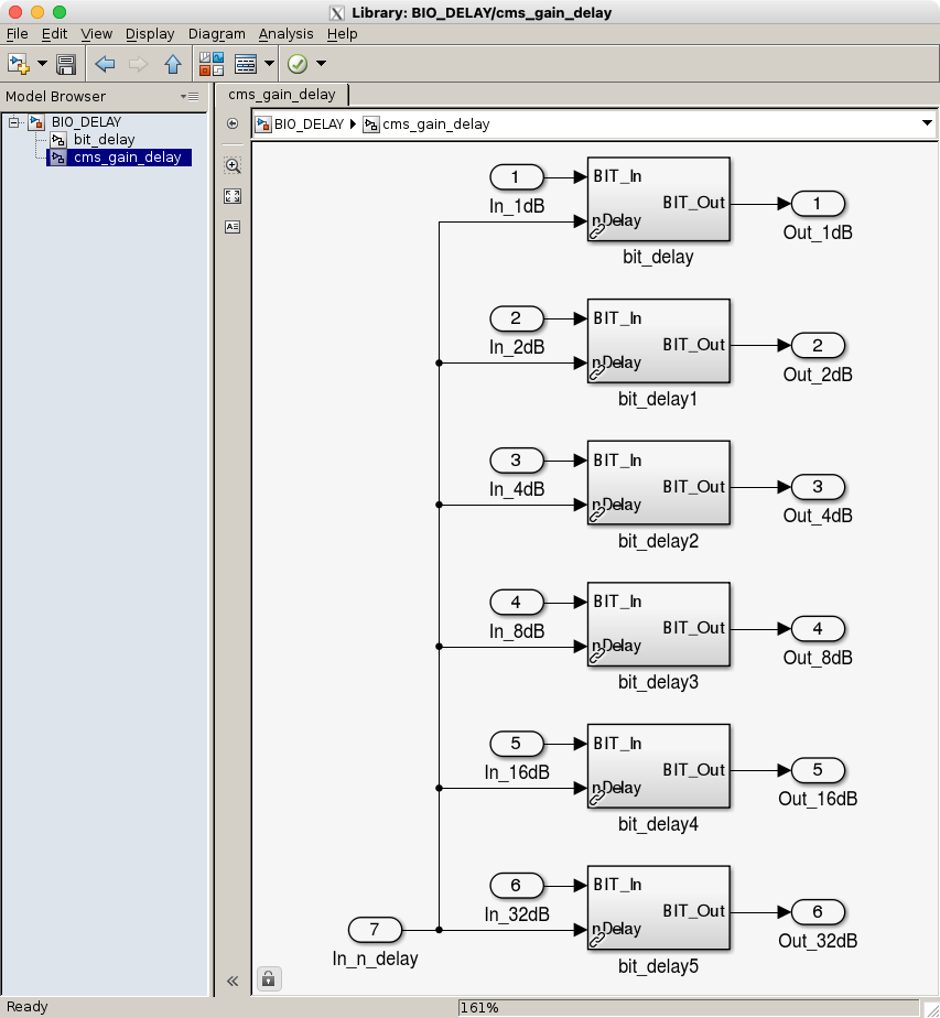
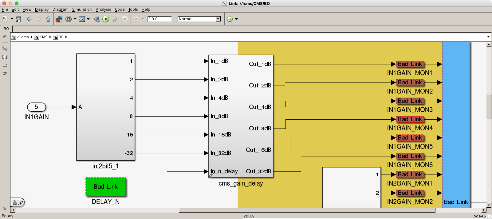
When we change the gain (of IN1) from 16dB to 15dB, the output (OUT1 or OUT2) looks changing as 16dB -> 31dB -> 15dB.

By looking at the digital inputs to CM servo board, we confirmed that the timing of binary output changing from 0 to 1 is delayed for ~150us from the timing changing from 1 to 0.  (2nd figure)

Contec, the manufacturer of the binary IO boards, says this is within the specification of "output response time <= 200usec".

These binary IO boards utlise photo-couplers to isolate the inputs/outputs from the PC power line, and it is normal that the turn-on and turn-off times are asymmetric for photo-couplers.

Images attached to this report
Comments to this report:
takahiro.yamamoto - 16:35 Saturday 06 April 2024 (29114) Print this report

Test of mitigating a timing gap
I prepared a real-time code block in order to reduce a timing gap of ON and OFF of BO. Because it is known that OFF is always delayed more than ON due to the characteristics of photocouplers, the timing gap is reduced less than half of the sampling interval by adding N-sample delay for ON.

Test of this code was done on the standalone system in the Mozumi circuit room and worked as intended. Figure 1 shows the channel 3 (for 8dB) and channel 4 (for 16dB) of BO output when 8dB was turned OFF and 16dB was turned ON in simultaneously. In this measurement, I didn't add an intentional delay for turning ON and a ~140us timing gap can be seen between the edge of two channels. Figure 2 shows same plot with 2-sample delay of 16kHz (~122us) for turning ON. In this case we can see that the timing gap between ON and OFF is reduced as ~20us.

Real-time code implementation
At first, I considered to modify the BO/BIO driver code to align a timing of ON and OFF. But it's difficult to know what kind of circuit is connected to BO card in the driver code. Because of this, modifying the driver code makes a timing gap between turning ON analog whitening/dewhitening filters and turning ON digital anti-whitening/anti-dewhitening filters. (Now there should be a 100-200us timing gap between turning OFF analog filters and turning OFF digital filters. In most case, only turning ON is done in the lock acquisition and turning OFF is done when lockloss occurs. So we don't have a problem?). Anyway, I prepared it as a real-time code block that gives a bitwise delay as shown in Fig. 3. For the gain bits of CMS, additional delays are applided for only 6 bits as shown in Fig.4 and Fig.5.

Images attached to this comment
takahiro.yamamoto - 0:42 Wednesday 10 April 2024 (29153) Print this report

[Tomura, YamaT]

We measured circuit noise at just after the input gain stage of CMS (OUT2) with a new real-time code when the gain was changed from 16dB to 15dB.

Figure 1 shows the case of no additional delay for turning ON BO signal. Because a timing of turning OFF is delayed as ~180us from one of turning OFF, gain is changed as 16dB -> 31dB -> 15dB. Figure 2 and 3 shows the case of 1-sample (61us) and 2-sample (122us) delay for turning ON, respectively. Though a timing gap is not compensate completely in the case of figure 3, the timing gap can be mitigated. Figure 4 shows the case of 3-sample (180us), turning OFF occurs earlier than turning ON. So gain is changed as 16dB -> 0dB -> 15dB.

A timing gap can be mitigate from ~180us to ~40us (Fig.3 and Fig.4). In the case of Fig.3, UGF increases as ~600kHz while gain becomes 31dB. A timing gap of 40us seems to be too long. On the other hand, UGF decreases as ~17kHz while gain becomes 0dB in the case of Fig.4. A timing gap of 40us may be acceptable in this case. In order to confirm this timing gap is acceptable for the lock acquisition, we need to test this real-time code after IFO comes back.

Images attached to this comment
takahiro.yamamoto - 1:23 Friday 12 April 2024 (29200) Print this report

[Tomura, YamaT]

We found that CMS had a latch control input. So we prepared a real-time model that uses this latch control.
It was confirmed that the timing gap between turning ON and turning OFF could be sufficiently small thanks to the latch control
Figure 1 shows the readout voltage at OUT2 when the IN1 gain was changed from 16dB to 15dB.
A remaining concern is whether a glitch at a timing of switching makes a lockloss or not.

-----
Gain channels and the latch channel are output from another BO card because of pin assignment. For this reason, N-sample delay may be needed to compensate individual differences between another cards. So I implemented a new real-time code as the combination of the N-sample delay block which is implemented in the previous post and the latch control block (see Fig.2 and Fig.3).

Delay sample can be set from the EPICS record. If the individual difference between the two BO cards installed in K1IOO is small enough delay sample should be set as 0. On the other hand, if it's large we may set a proper number of delay sample. Anyway, proper number of delay must be decided to check the actual delay of the BO card in K1IOO. It cannot be decided on the standalone system. And also, the latch control can be disabled by setting OFF to the LATCH_USE EPICS records. Even if we install a new code, we can use CMS also as the no latch control and no delay mode same as the original code.

Images attached to this comment
Search Help
×

Warning

×