Summary:
Is 5mV jump in the IMC error point reasonable? The answer is it's not totally unreasonable though we have to be unlucky.
In the worst case (all AD829 opamps for the IN2 buffer, differential->single conversion and whitening stages have the maximum 1mV input offset voltage and they all add up in the same sign), the offset would be ~7.5mV for the IN2 gain of -10dB.
As such, the problem seems to be that the IMC error signal is too small before IN2 is added. If we can reduce the analog gain for the NPRO PZT drive path (e.g. by a factor of 2 or 4), reduce the FAST gain, increase the IN1 gain and e.g. increase the FAST gain of CARM board at the same time, it would be good (but you'll reduce the range of the PZT control, which may or may not impact the locking).
Another mitigation strategy, though not a great one, is to increase IN2 gain (K1:IMC-SERVO_IN2GAIN, -10dB as of now) and decrease CARM FAST gain (K1:LSC-CARM_SERVO_FASTGAIN, +5dB as of now) at the same time to keep the total gain for CARM->IMC path constant, and search for a combination that minimizes the offset. For example, if you set the K1:IMC-SERVO_IN2GAIN to -8dB, the worst case IN2 offset coming from the IMC board opamps themselves self would be 3.6mV, not 10mV.
Details:
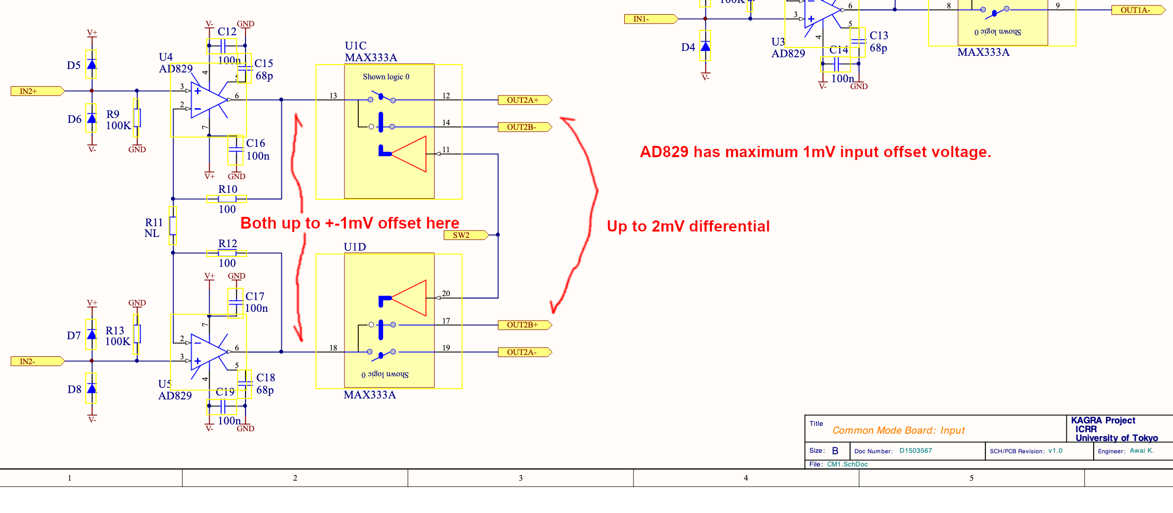
IMC servo board is https://gwdoc.icrr.u-tokyo.ac.jp/cgi-bin/private/DocDB/ShowDocument?docid=3567. I looked at the circuit diagram with Kamiizumi-san and Tomura-san.
IN2 chain upstream of the IN2 summation point comprises the differential receiver (1st attachment), differential->single ended conversion (1st opamp on the 2nd attachment), whitening stages (2nd and 3rd attachment) and the buffer (last opamp of the 3rd attachment).
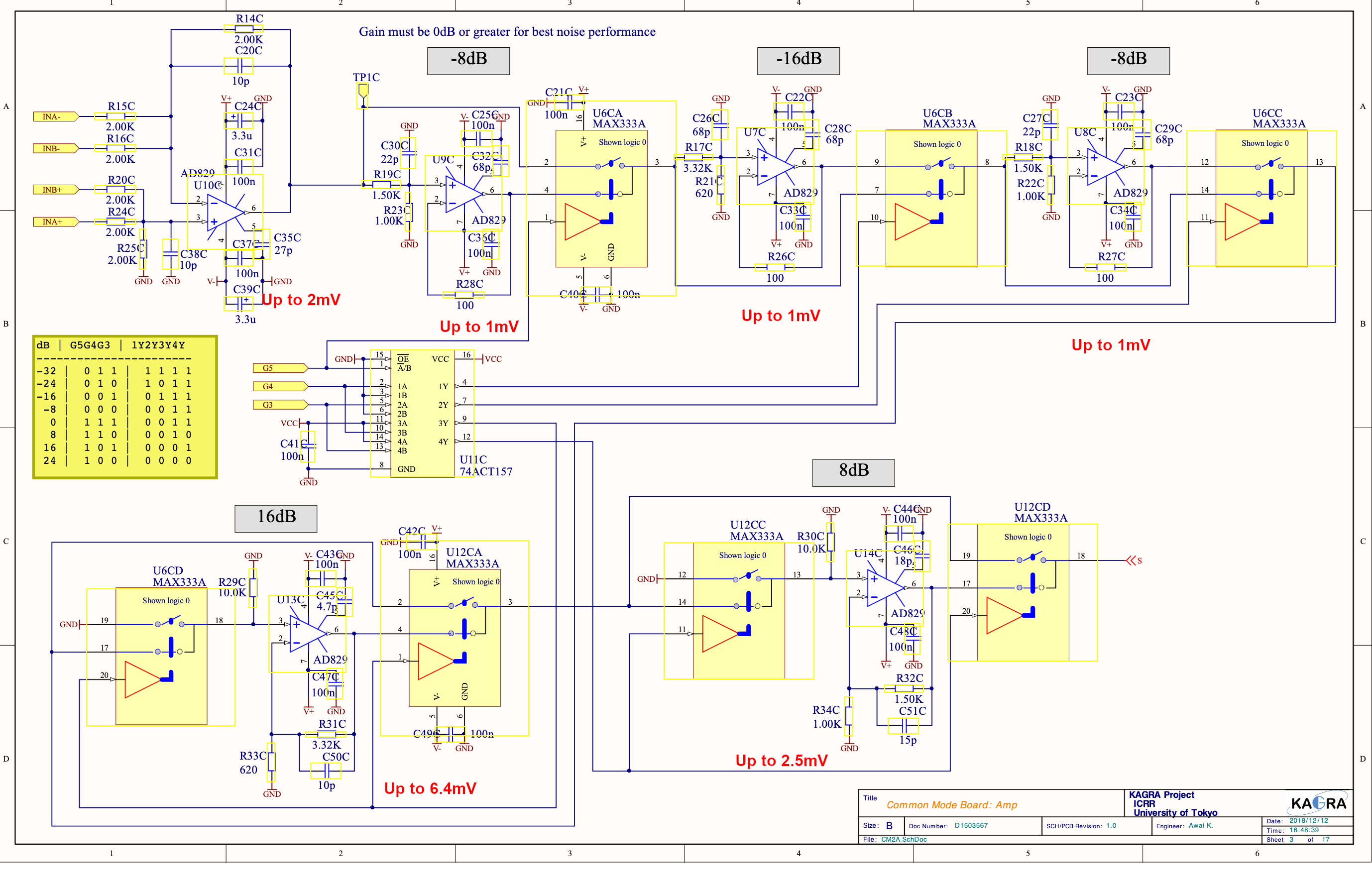
All opeamps are AD829 with 1mV or smaller input offset voltage. Diff receiver output offset is up to 2mV, diff->single adds another 2mV, these cannot be bypassed so they will produce up to 4mV of offset at the output of the diff->single converter. That will be amplified according to the whitening stages (i.e. if the whitening gain is -10dB, up to 4mV will become up to 4mV*10^(-10/20)=1.3mV in the output of the last opamp in the 3rd attachment).
Likewise, each whitening stage with negative dB (-16dB, -8dB) will produce up to 1mV in the output of the opamp, which will go through the gain stages downstream.
Each whitening stage with positive dB (16dB, 4dB, 2dB, 1dB) will produce up to 1mV times the gain of that stage in the output of the opamp (e.g. for 8dB stage, it will be 1mV*10^(16/20)=2.5mV), which will go through the gain stages downstream.
Final buffer in the chain will produce up to 1mV.
The offset will of course depend on the whitening gain (as well as the input offset voltage of opeamps involved). As such, you can change IN2 gain while monitoring OUT2 and see which gain will produce a better offset.
With -10dB gain, -16dB, 4dB and 2dB stage will be used. In this case the offset would be 4mV*10^(-10/20) + 1mV*10^(6/20) + 1mV*10^(6/20) + 1mV*10^(2/20) + 1mV ~ 7.5mV in the worst case.
With -16dB gain, it would be 4mV*10^(-16/20) + 1mV + 1mV ~ 2.6mV in the worst case. With -8dB gain it would be up to 3.6mV.
That there should be up to 1mV offset coming from the HPF output of the CARM FAST path into IN2 of IMC board, too, but that offset won't depend on CARM FAST gain.
