Reports 1-1 of 1 Clear search Modify search
VIS (IY)
ryutaro.takahashi - 17:50 Wednesday 27 March 2024 (28993) Print this report
Re-cabling of BF damper

[Ikeda, Washimi, Takahashi]

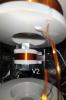
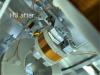
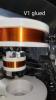
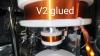
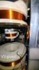
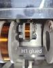
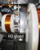
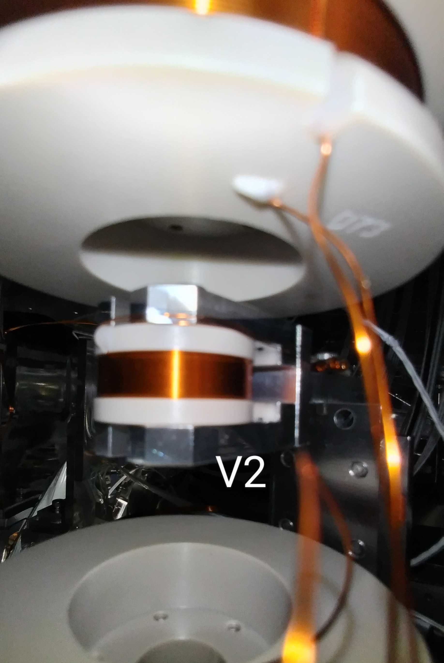
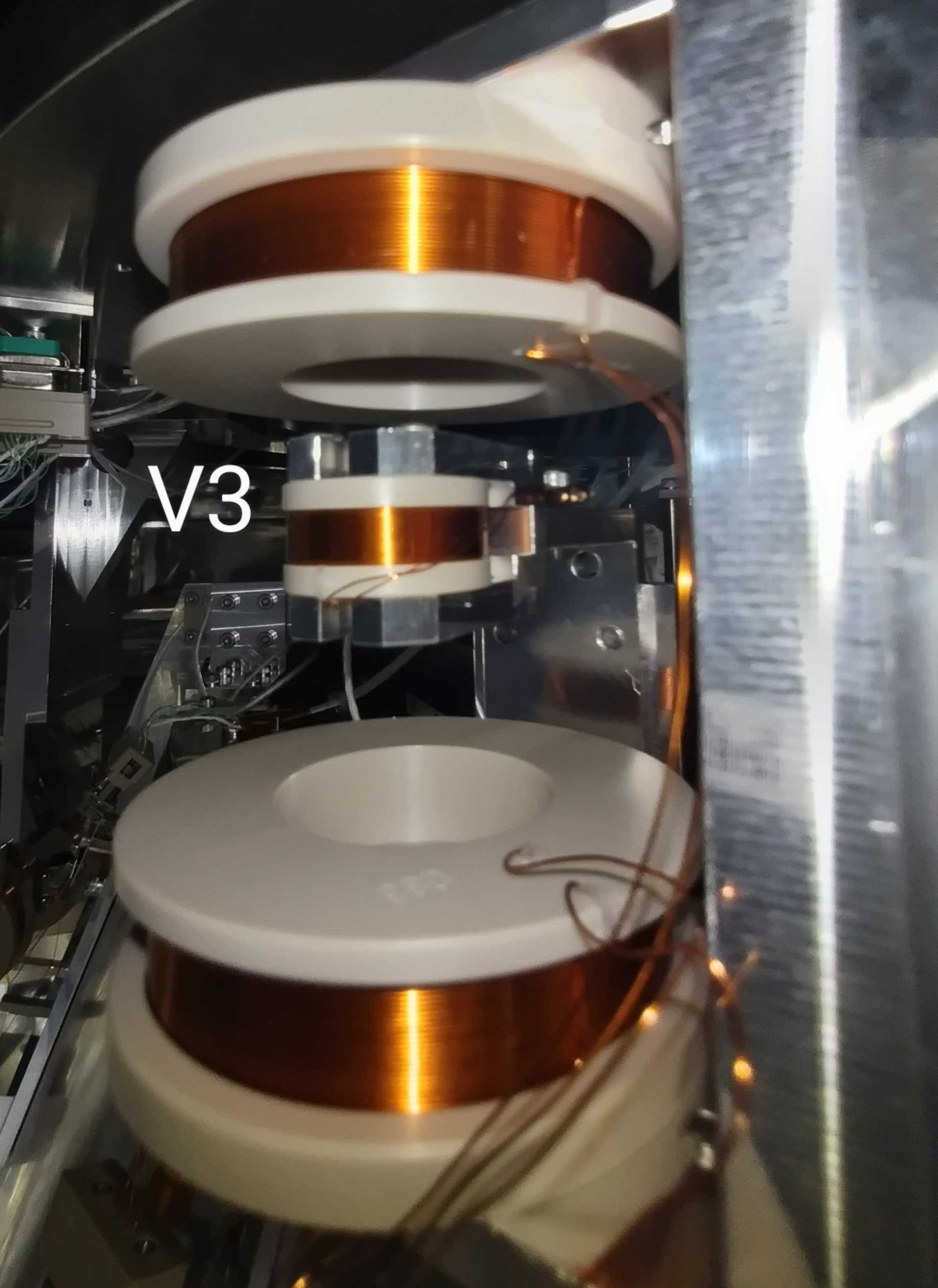
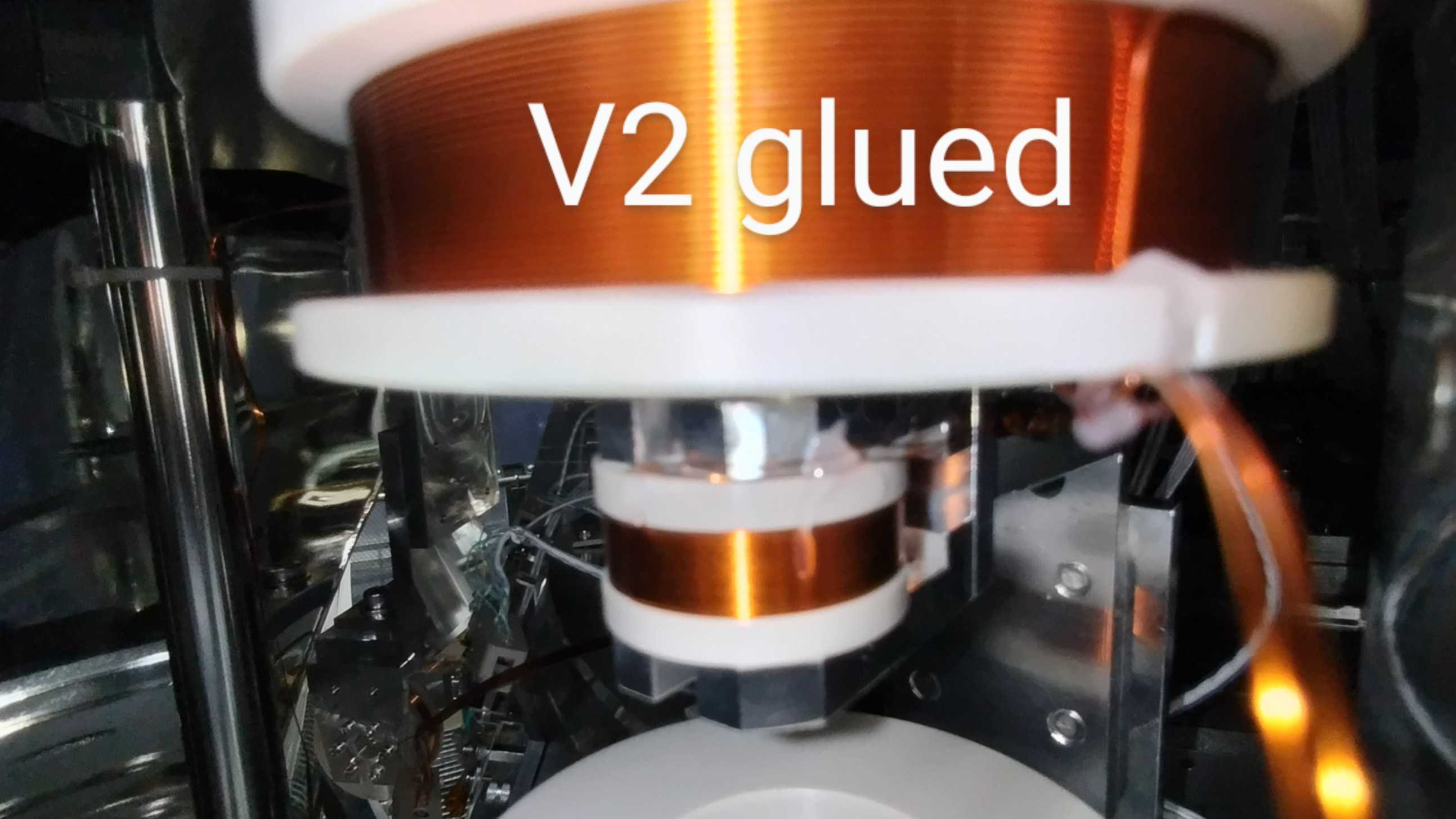
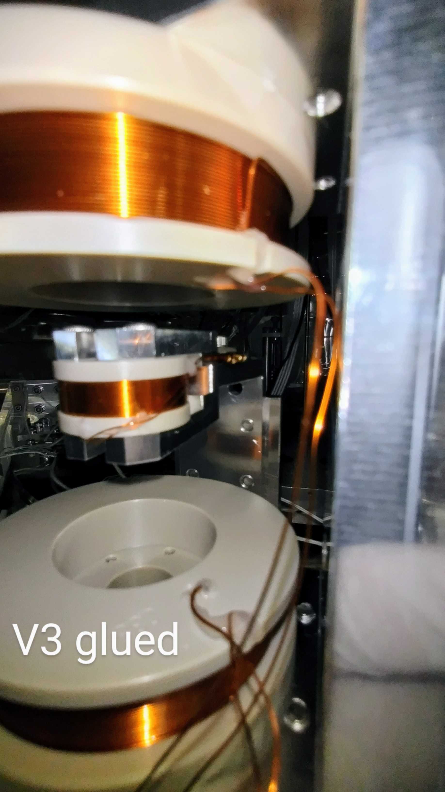
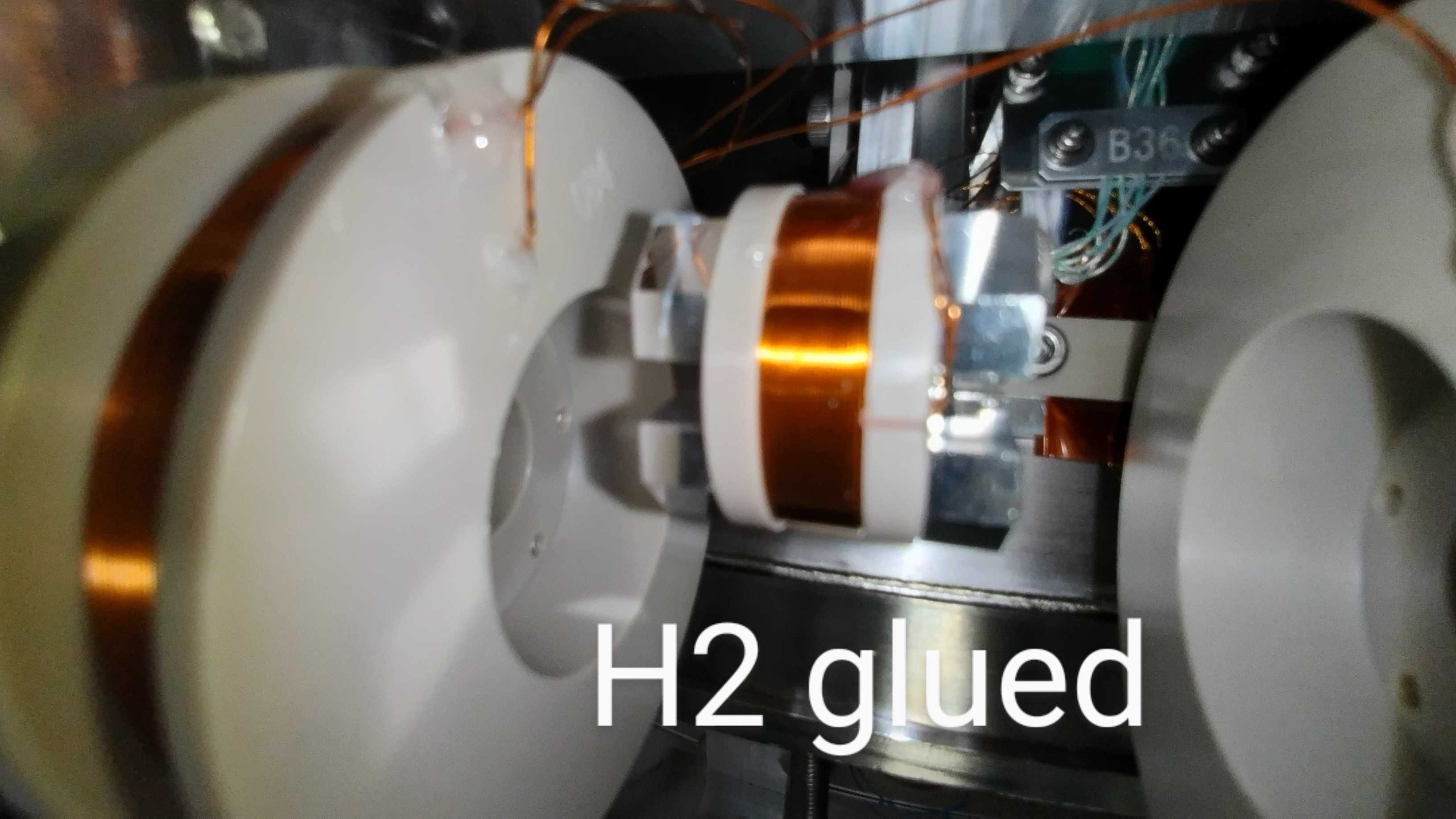
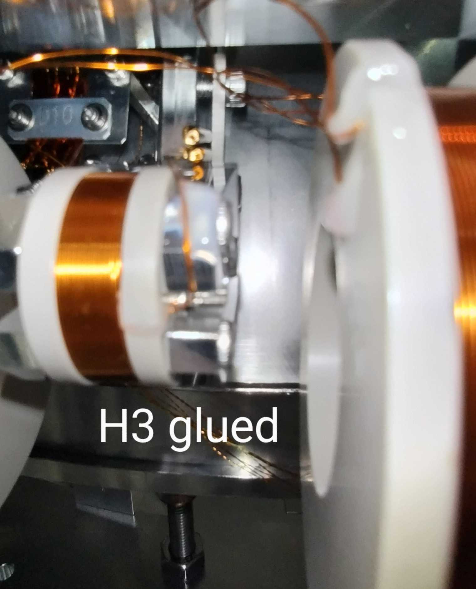
We applied new cabling to the primary coils for the BF damper. The lead wires for V2, V3, and H3 coils were re-cabled on the side of the coil bobbin with the PEEK plate. Additionally, the lead wires of the coils were fixed on the coil bobbins with an adhesive (TRA-BOND 2116).

Images attached to this report
Comments to this report:
ryutaro.takahashi - 17:02 Wednesday 10 April 2024 (29177) Print this report

[Washimi, Takahashi]

We checked the resistance and inductance of the LVDT coils for the BF damper at the feedthrough flange with the flip cable.

  Before O4a This time

1 BF DPCH

1-6

2-7

3-8

4-9

5-G


25.5Ω/1.066mH

26.2Ω/1.066mH

25.6Ω/1.068mH

OL


27.8Ω/1.066mH

29.5Ω/1.064mH

27.6Ω/1.068mH

OL

~40MΩ

2 BF DPCV

1-6

2-7

3-8

4-9

5-G


26.2Ω/1.062mH

24.9Ω/1.067mH

24.3Ω/1.061mH

OL


29.4Ω/1.061mH

29.2Ω/1.095mH

28.6Ω/1.062mH

~70MΩ

~20MΩ

3 BF DSCH

1-6

2-7

3-8

4-9

5-G


24.5Ω/8.56mH

24.3Ω/8.53mH

23.6Ω/8.56mH

OL


27.9Ω/8.55mH

31.1Ω/8.53mH

27.0Ω/8.54mH

~50MΩ

~20MΩ

4 BF DSCV

1-6

2-7

3-8

4-9

5-G


24.2Ω/8.53mH

24.2Ω/8.53mH

23.4Ω/8.52mH

OL


27.6Ω/8.53mH

34.8Ω/8.52mH

26.6Ω/8.54mH

~50MΩ

~20MΩ

We found the breakout adapter with the lead cable had a resistance of 2~4Ω.

Search Help
×

Warning

×