Summary
Starting optical alignment recovery, and so far I can say most of the things good tendency; confirmed the forward p-pol beam spot (IMC resonance blocked) on STM1 close to its nominal location without tweaking any optics; also, roughly confirmed p-pol IMC flashing with zero-oplev alignment for MCi, MCo, and MCe, though with higher order mode mainly in yaw.
Forward beam on STM1
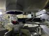
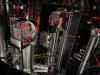
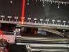
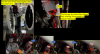
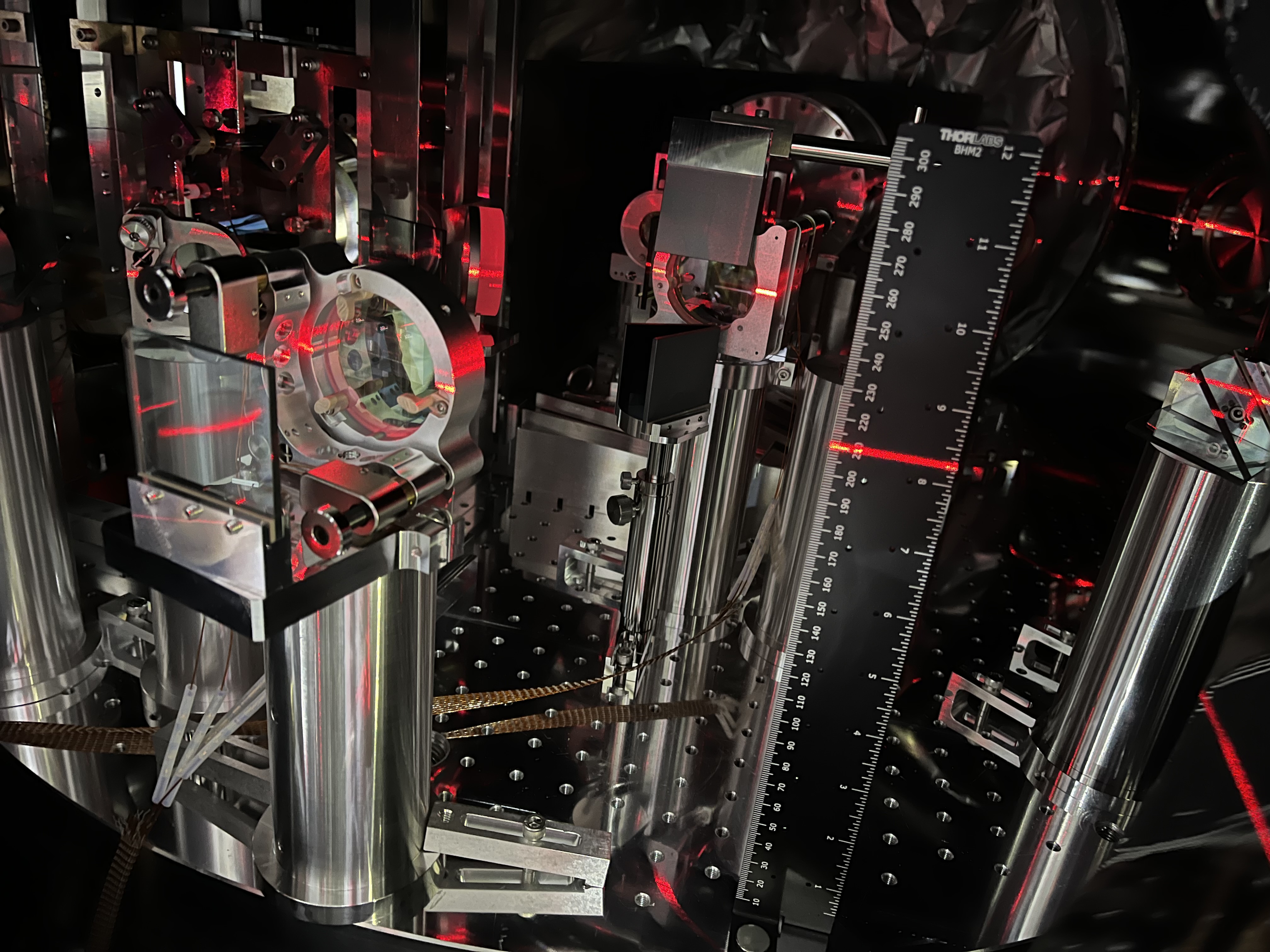
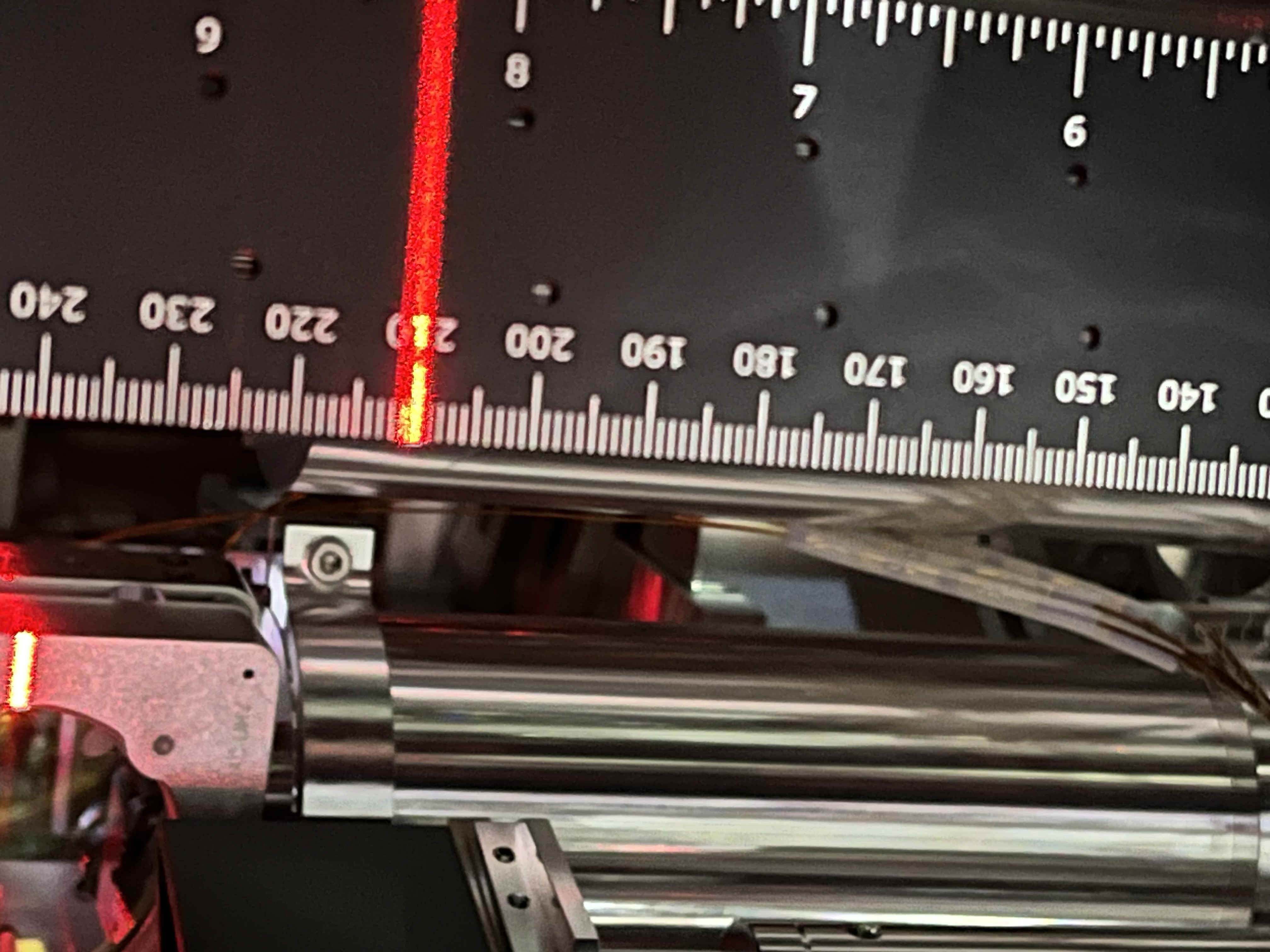
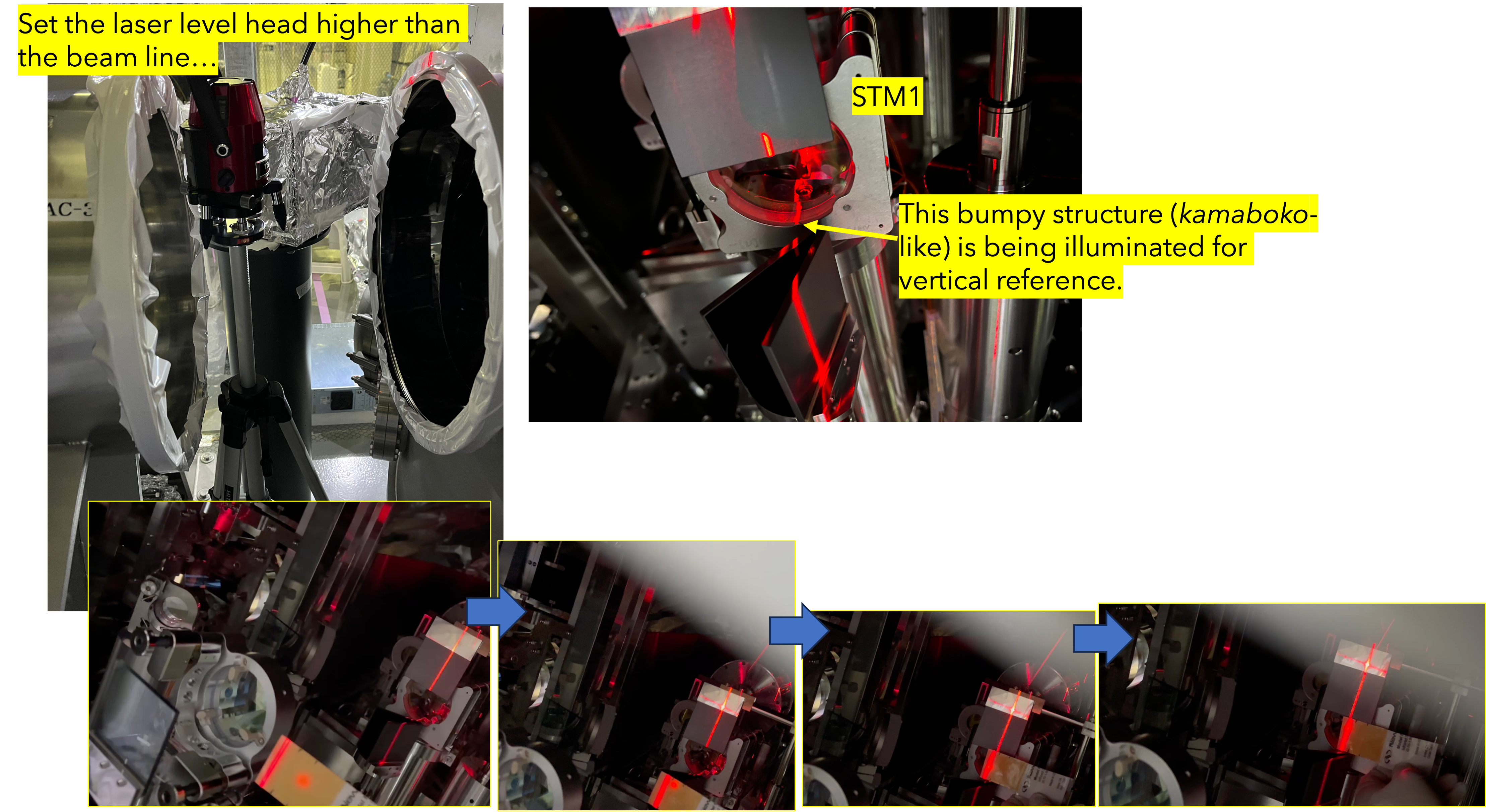
This morning I started with checking the beam spot location on STM1 in the IFI chamber. The input laser was kept p-pol as set in the end of January (28402). The IR beam itself was 210 mm above the top surface of the optical table in the IFI chamber (Figs. 1-3); see also 16289. The IR beam is basically on this laser level line, so its pitch would be ok (Fig. 4).
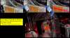
For yaw, it is hard to align the laser level vertical line to the STM1's vertical center line, as upper and lower of the STM1 holder is hidden by beam dumps. Resetting the laser level head higher, and let it shoot the laser from the above, and illumate a bottom bump of the STM1 holder as a reference of the center, I assumingly set a vertical reference as a a zero yaw location (Fig. 5). Comapred with this reference, the forward beam spot on STM1 seemed 0-0.1 mm off the center line in the minus Y direction, while the nominal yaw position should be 2.7 mm off the center the minus Y direction (see also 16300). For the beam spots on STM1 and STM2, please see the attached pdf files in 18487.
But I guess this error can be acceptable for now. One of the reason is that the laser level line has 2-3 mm width and it is hard to distinguish this small error. Another reason is that, as reported above, it was hard to surely put the vertical reference laser level line in the current situation. Also, the aperture of a HWP to convert S to P tentatively located in the PSL room is small (see 28402), so it might also affect the beam spot location on STM1. So I left it as was, and did not do fine tuning of IP2, which is the final steering mirror in the PSL room.
IMC resonance in P-pol
Next, I uncovered aluminum foils at the MCE flange to check the IMC resonance of the p-pol beam. Note that currently MCi, MCo, and MCe are aligned so that their relevant oplevs show nearly zero. Before leaving MCE, I roughly confirmed the input and reflected beam spots were at the same height. Then, I could see sufficient flashing from IMC. It contained still much higher order mode in yaw, but not so much, so the goal alignment would be very close. Maybe no need to adjust with pico anymore. The reference with oplevs are so robust! Today I did not take finer alignment of this p-pol IMC, as I guess this alignment should be sufficient for comfirmation of the optical alignment in the downstream.
Note and to do
- I also checked STM2, which would be a source of beam jitter. As I have been proposing, its pedestal should be reinforced more, and today I thought that elecrtric wires from the STM2 holder might be also a possible cause of this beam jitter. These wires should be tamed somehow before closing the chamber as well.
- The Finer IMC alingment should be done later with p-pol, but that should be done after additional installation of EQ stops.
- Before getting back beam shield plates to each suspension structure in the near future, it might be better to do final check of the beam spot positions somehow with laser levels later, though I believe they would be in a good alignment already from today's inspection.
- Note that currently the high-quality viewport window for MCE_TRANS was detached and the flange was sealed with aluminum foil; the MCe transmitting beam cannot be detected.