Cont'd from 16289; Yano, K. Tanaka, Akutsu; on Mar. 19, 2021
Abstract
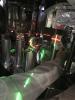
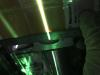
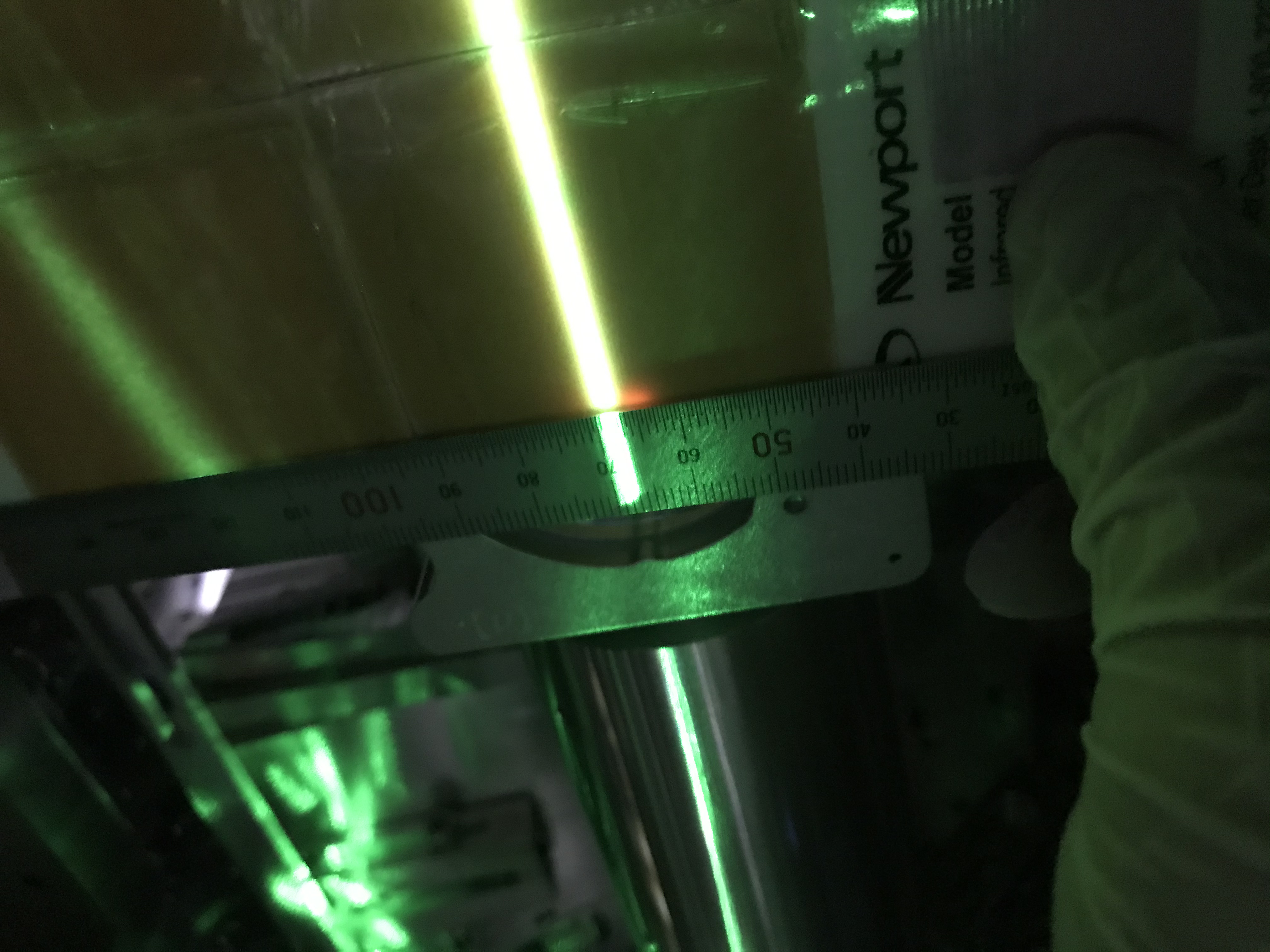
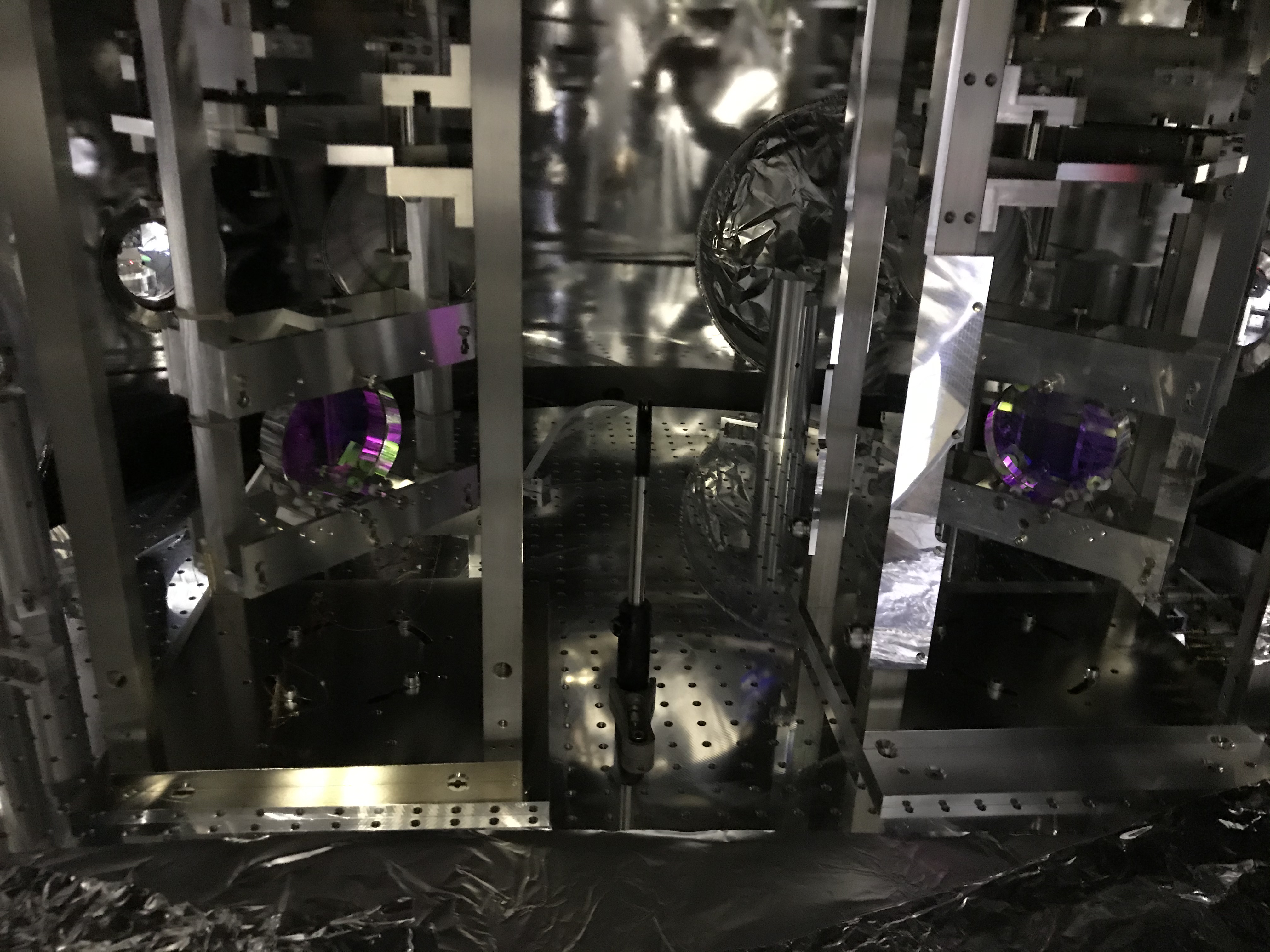
Aligned the input beam from the PSL room to STM1 so that the beam spot came at the "designed" position on STM1. (Fig. 1 -> Fig. 2) On MCe, the beam spot moved in pitch and yaw (Fig. 5).
Detail
Beam spot adjustment on STM1
By adjusting IP2, which is the last steering mirror in the PSL room, we aligned the input beam from the PSL room to STM1 through MCi and MCo so that the beam spot came at the "designed" position on STM1. IP2 is mounted on a mirror holder having two adjustors (maybe Thorlabs polaris-K2S2P), where a PZT and a manual adjusters are integrated in the adjuster. According to the mirror mount manual, PZT could adjust less than a few urad, while the manual could do a few deg.
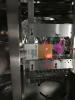
We would need to adjust the beam angle ~ a few mrad. The input beam must come at (pitch, yaw) = (0 [centered], 2.7mm( -Y side)) accoording to our design. Here, the design means a combined information derived from my personal ray trace several years ago and the actual mechanical position of STM1 in the IFI chamber now (Sato-san somehow prepared). Comparing the actual situation observed in 16289, we learned that we needed to move about a few cm in yaw and pitch, while it was about 10m(??) from IP2 to STM1; so a few cm / 10m = a few mrad. So we needed to adjust the mirror by the manual screw part.
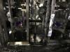
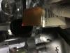
Before starting the adjustment, we put an iris diaphragm (or aperture) in-between MCi and MCo for remebering the original beam line (Figs. 3 and 4). It may be better to put another iris, but we could not find a nice place for that. With this we may check if the beam and mirrors has been relatively located according to our design or not (if not... how should we do...??)
After adjusting the iris with the beam, we widened the aperture of the iris. Then, I (Akutsu) entered the PSL room, and Yano-san and TanaK-kun were aruond IFI to place the sensor card and take the live video by zoom, and so we adjusted IP2. By the way, after setting the laser levels, we did not need to use the two at once; we can use one of the laser levels one by one to adjust the beam spot on STM1 in pitch and yaw, one by one; otherwise the work place around STM1 was so crowded. Anyway, in this manner, we adjusted the input beam. Now the beam spot would be around the "designed" location on STM1 (again, Fig. 2).
Beam spot displacement on MCe
On MCe, the beam spot moved in pitch and yaw (Fig. 5). If the beam passes through the centers of MCi and MCo, it would be better to start with adjusting MCo's alignmet to have the beam shoot the MCe center point. Anyway, we found the reflected beam at MCi as well. When adjusting MCo, be careful that the beam is not reflected at the inner surface of the beam tube in-between MCF and MCE. We should have done the innput beam alignment also observing the spot moving on MCe...
By the way, how about the amount of the beam spot displacement on MCe? In pitch, it seems about -5cm moving (a radius of the mirror diameter; see here) if the beam was at the center before ouor today's work; considering the length from MCo to MCe is about 26 m, the angle displacement was about 2 mrad. Hmm, is this consistent? In yaw, it seems about 2.5 cm moving if the beam was at the center before ouor today's work; so this is 1 mrad change, which would be consistent with the other information, right?
By the way, the beam spot on MCe seemed rather elliptic, and that is why I am worried whether the beam was hit at the inner of the beam tube on the way... check with the viewer as well!