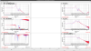
I measured TFs of PR2 for health check.
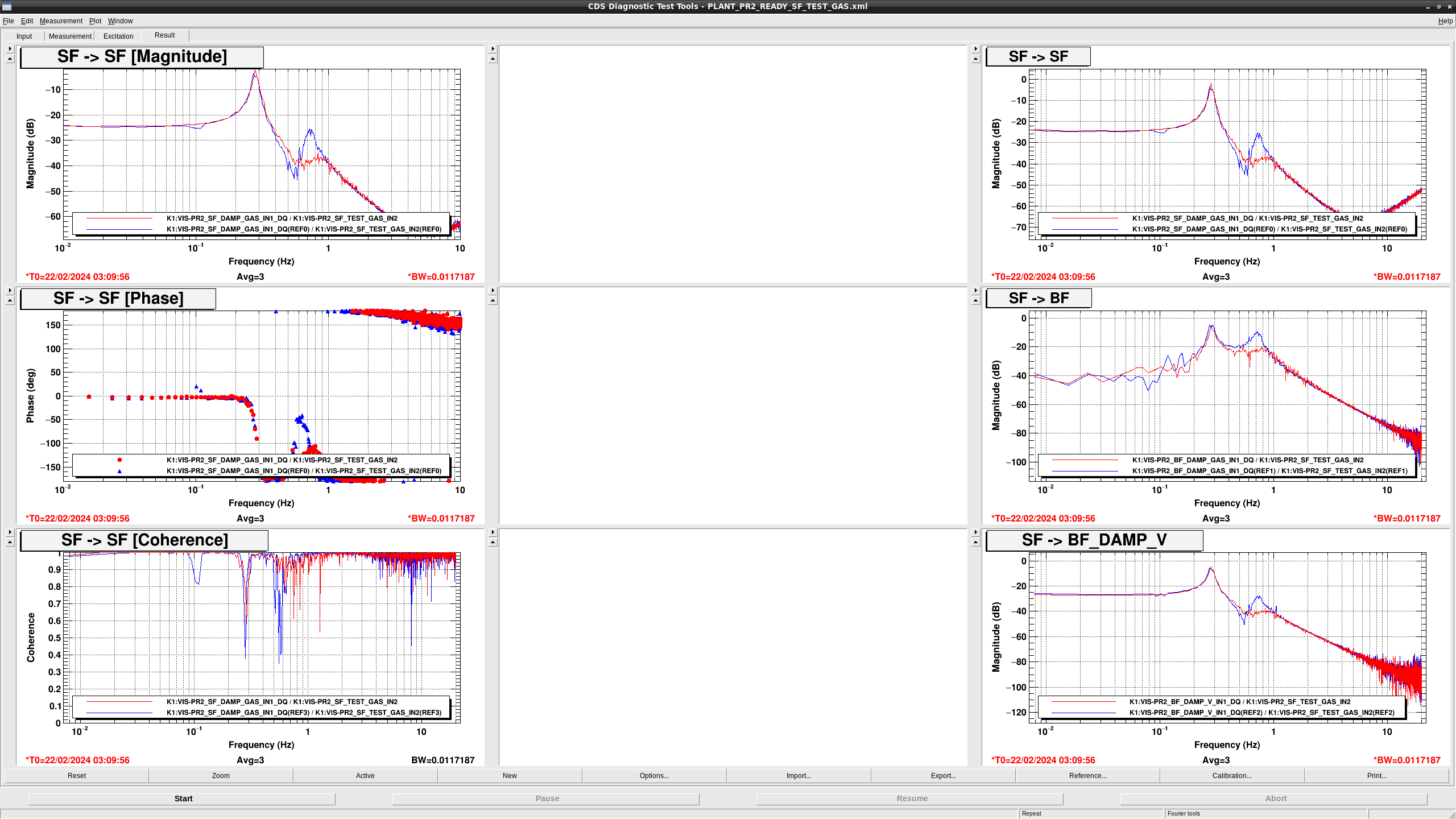
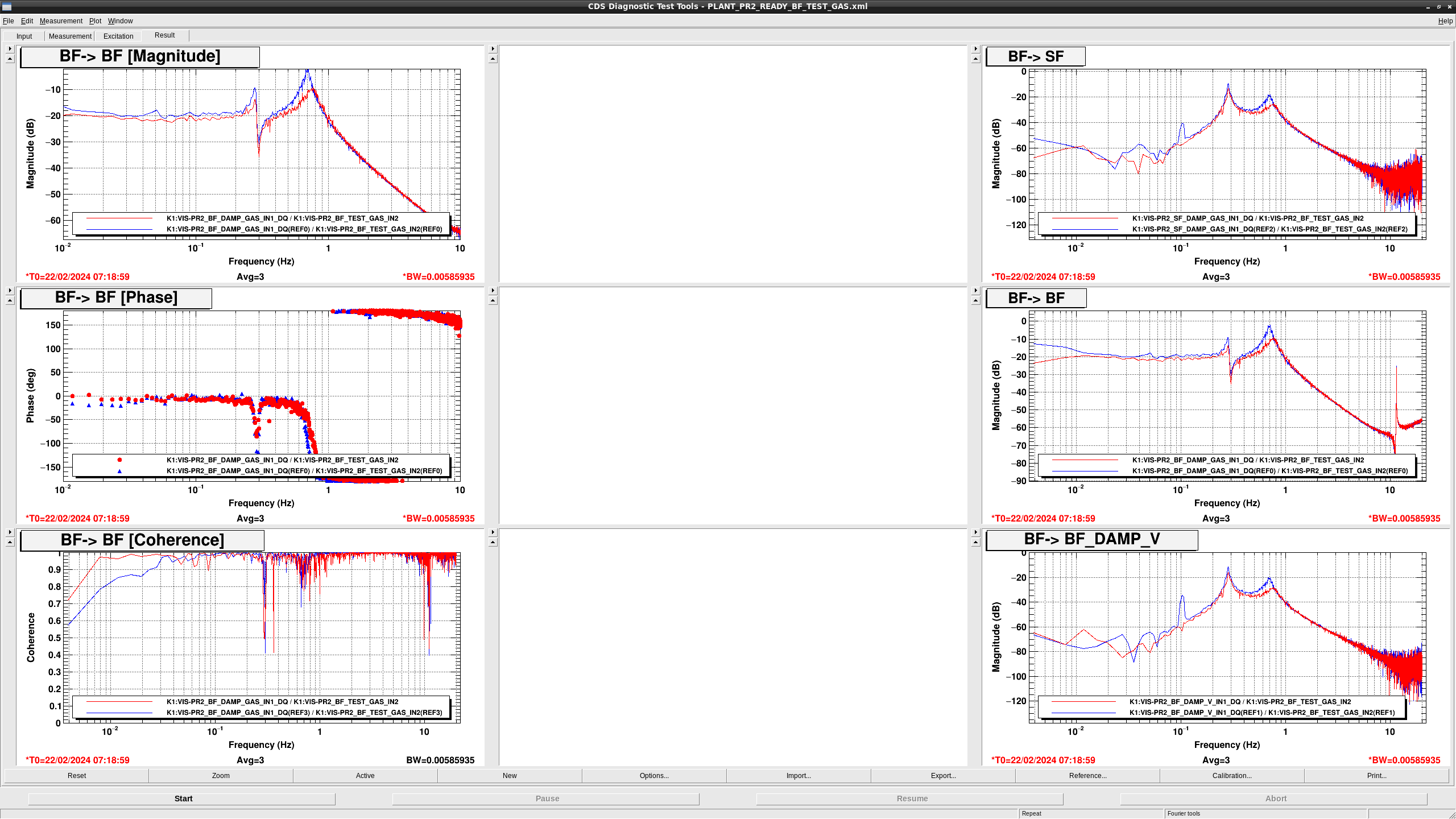
Though measurents haven't finished yet, vertical TFs seem strange, especially IMV, as shown in (fig1-3).
So, we need to check PR2 later.

Takahashi-sa pointed out excitation amplitude during TM COIL DoFs are too large.
So, I implemented notches at resonant frequency to avoid saturation of OpLev signals during the measurement (It works before so should be OK though...).
Let's see what happens...
[Takahashi, Hirata, Ikeda]
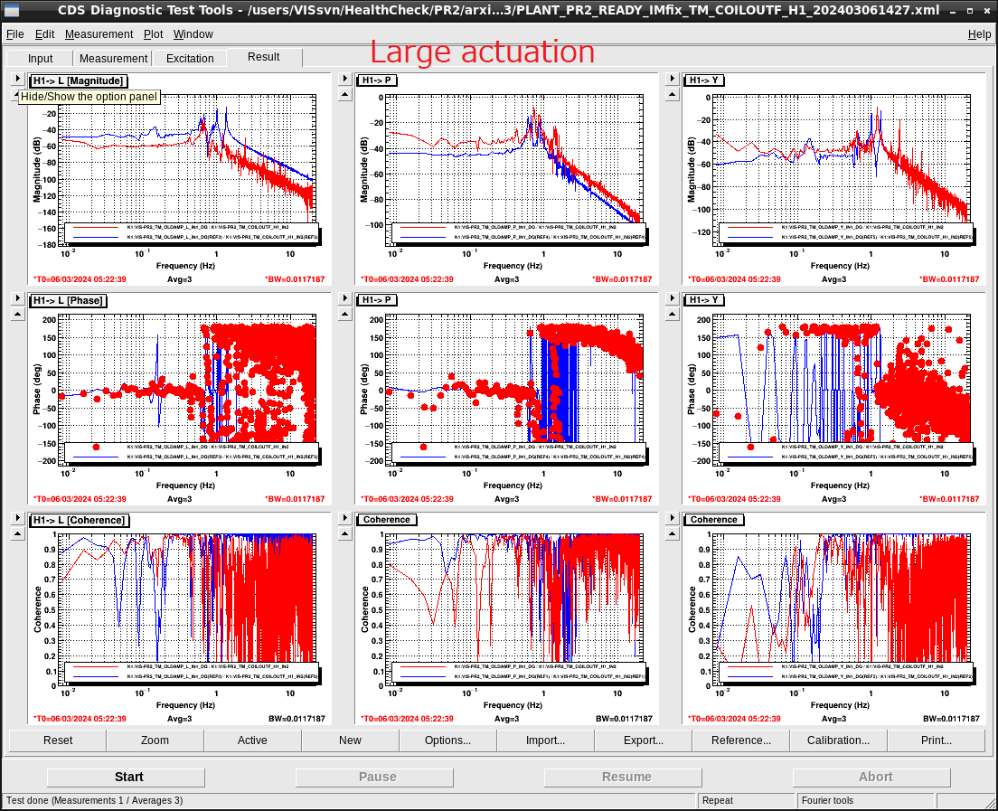
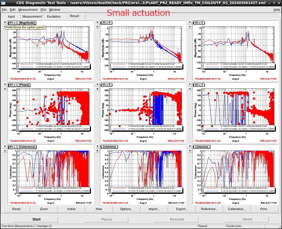
The results of the health check showed the TF from each TM actuator (H1~H4) to the Oplev signals (L, P, Y) were not consistent with the previous measurement. We checked if some points were rubbing or not. We did not find any rubbing points in the TM, IM, and IRM. To reject the effects due to the upper part, we fixed the TM and measured the TF. When we used the Diaggui script for the health check, the Oplev signals were saturated by the large actuation. We reduced the actuation by 1/10, the measured TFs were improved.
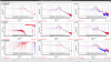
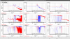
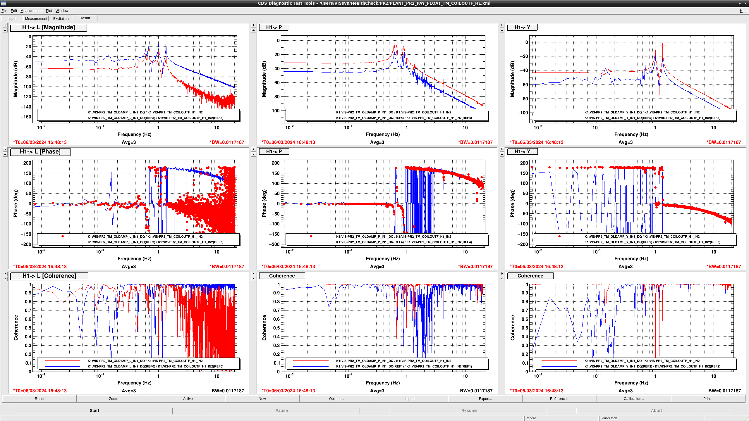
I checked the TF from H1 to OpLev with new template file.
In addition, I controled PR2 pitch to center of QPDs to avoid using OpLev out ot linear range.
Figure 1 shows the result.
TF shapes seem fine but gains are totally different from the previous measurement.
Also, TML TF becomes lower gains while P and Y have larger gain.
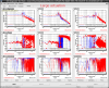
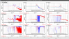
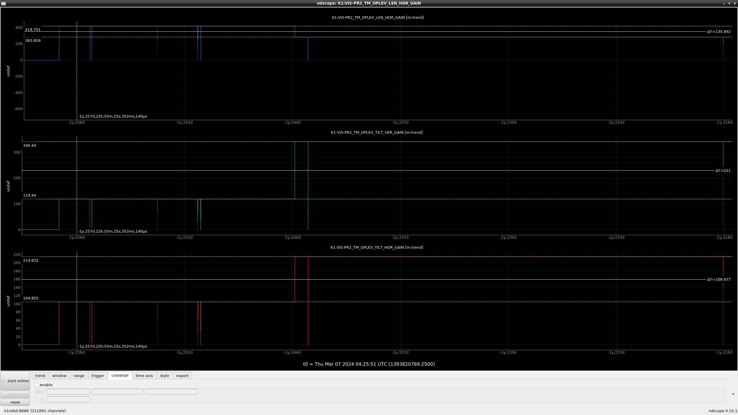
According to klog21408, recalubration was done after the measurement of reference, and L, P, Y gains are changed (fig2) as follows:
L: 420 -> 284
P: 120 -> 340
Y: 105 -> 215
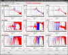
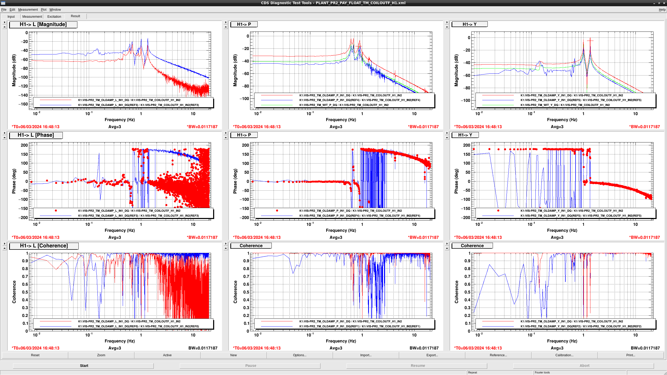
Green graph in fig3 show the TF from H1 to P/Y scaled with the calibration factor changes.
As you can see, gain difference becomes much smaller.
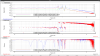
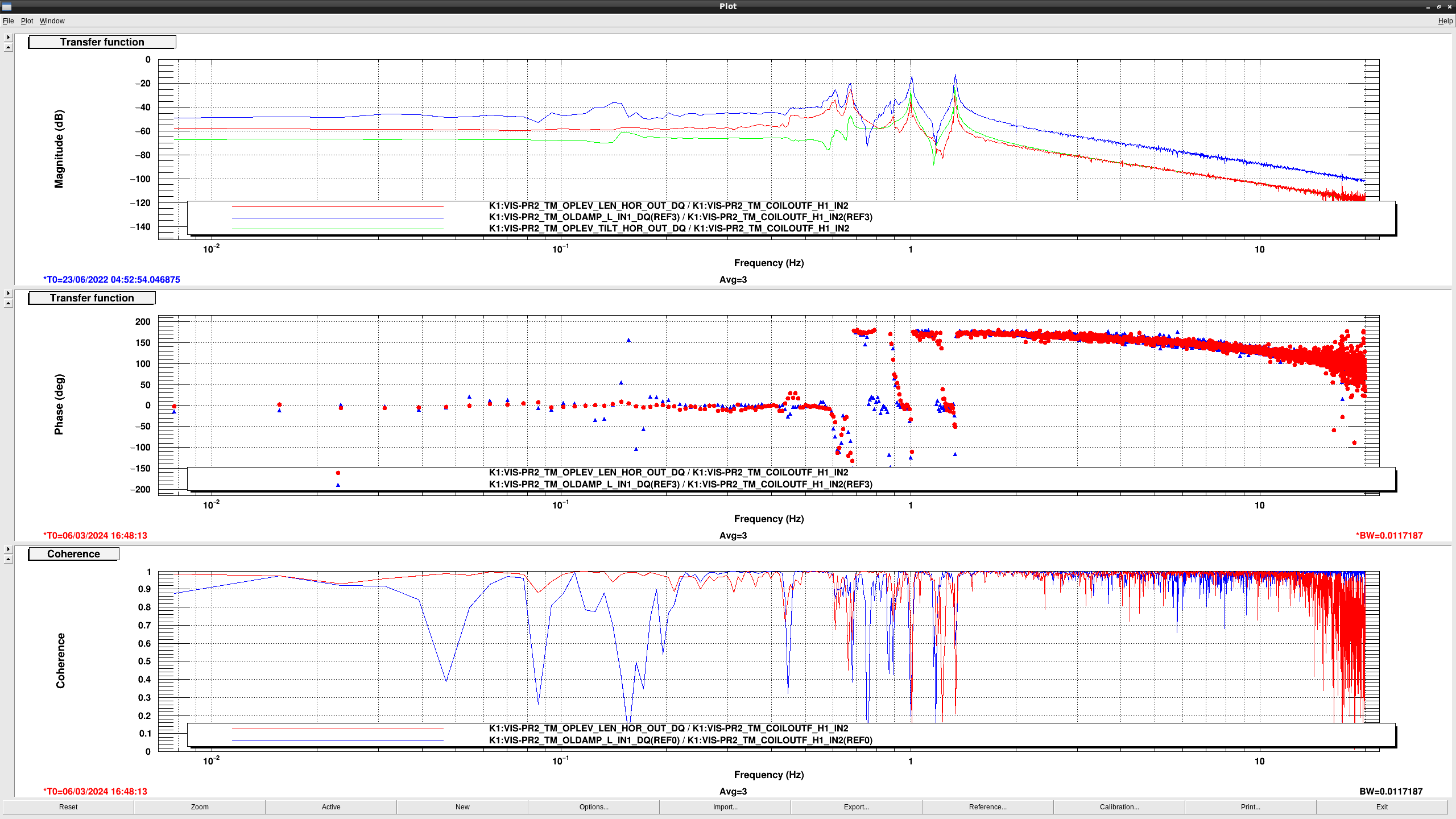
Re line in fig4 shows the TF from H1 to LEN QPD HOR signals, which is L signals before decoupling.
As you can see, coherence seems much better, so LEN sensor seems fine.
Green line in fig4 shows the TF from H1 to Y with a factor of 0.07, wich is the decoupling factor between L and Y.
As you can see, the gain of H1 to Y with 0.07 is almost same: that means LEN QPD signals see just a coupling from Y.
So, it might be changed due to the change of beam spot on the mirror, which needs to check later.
One remaining mystery is why the TF from H1 to decoupled L doesn't have f^-2 stracture at high frequency.
We need more careful investigation.