I ran the automeasurement script for ITMY health check on k1ctr3 from 21:09.
Data will be stored at /users/VISsvn/HealthCheck/ITMY/.
I checked the TF results, except for TM stage. I wrote down what I noitced as follows.
F2 GAS is needed to offload.
## IP
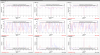
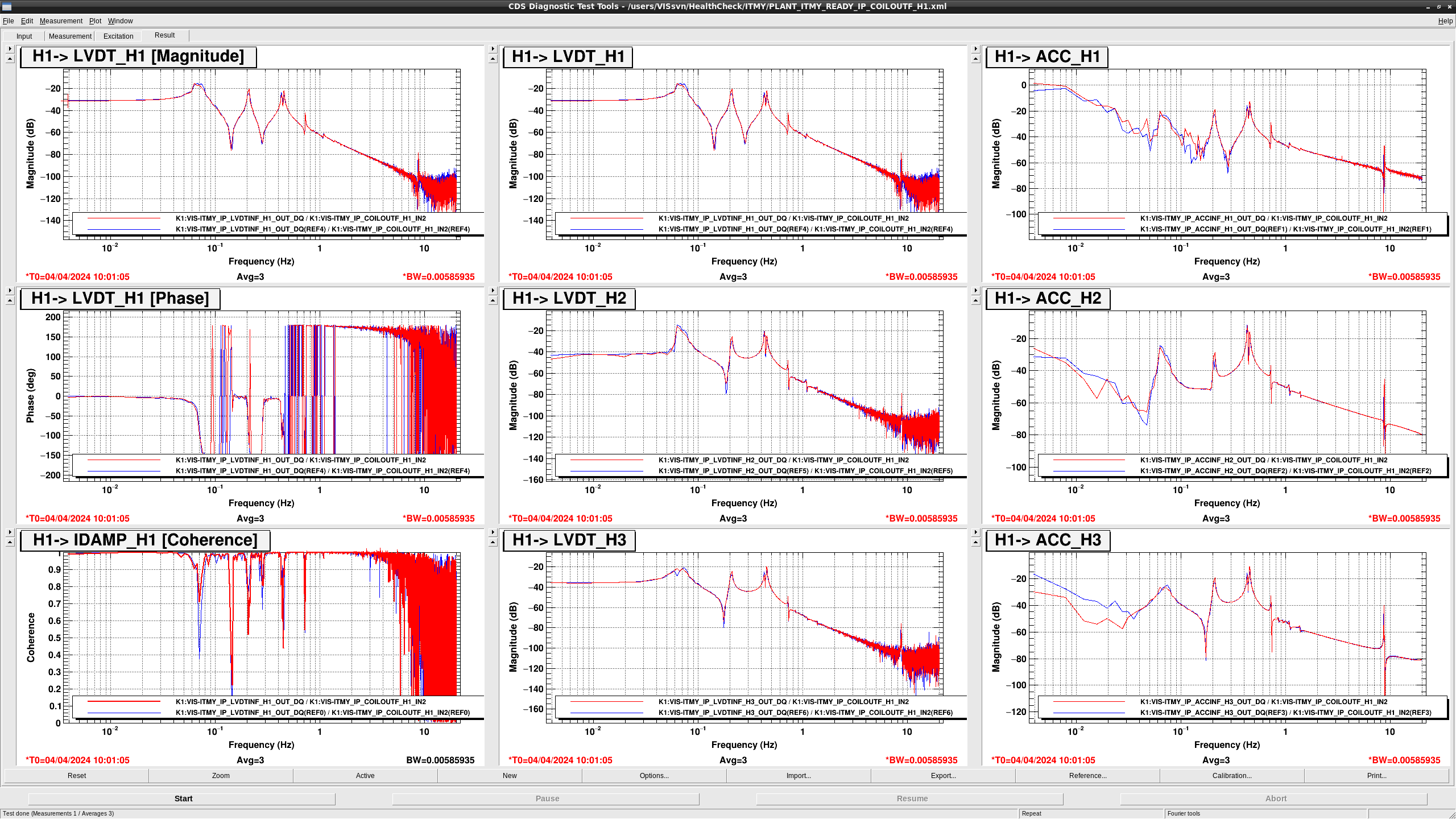
- The Q of the 0.14 Hz zero in COIL H{1, 3}-> LVDT H{1, 3} became lower.
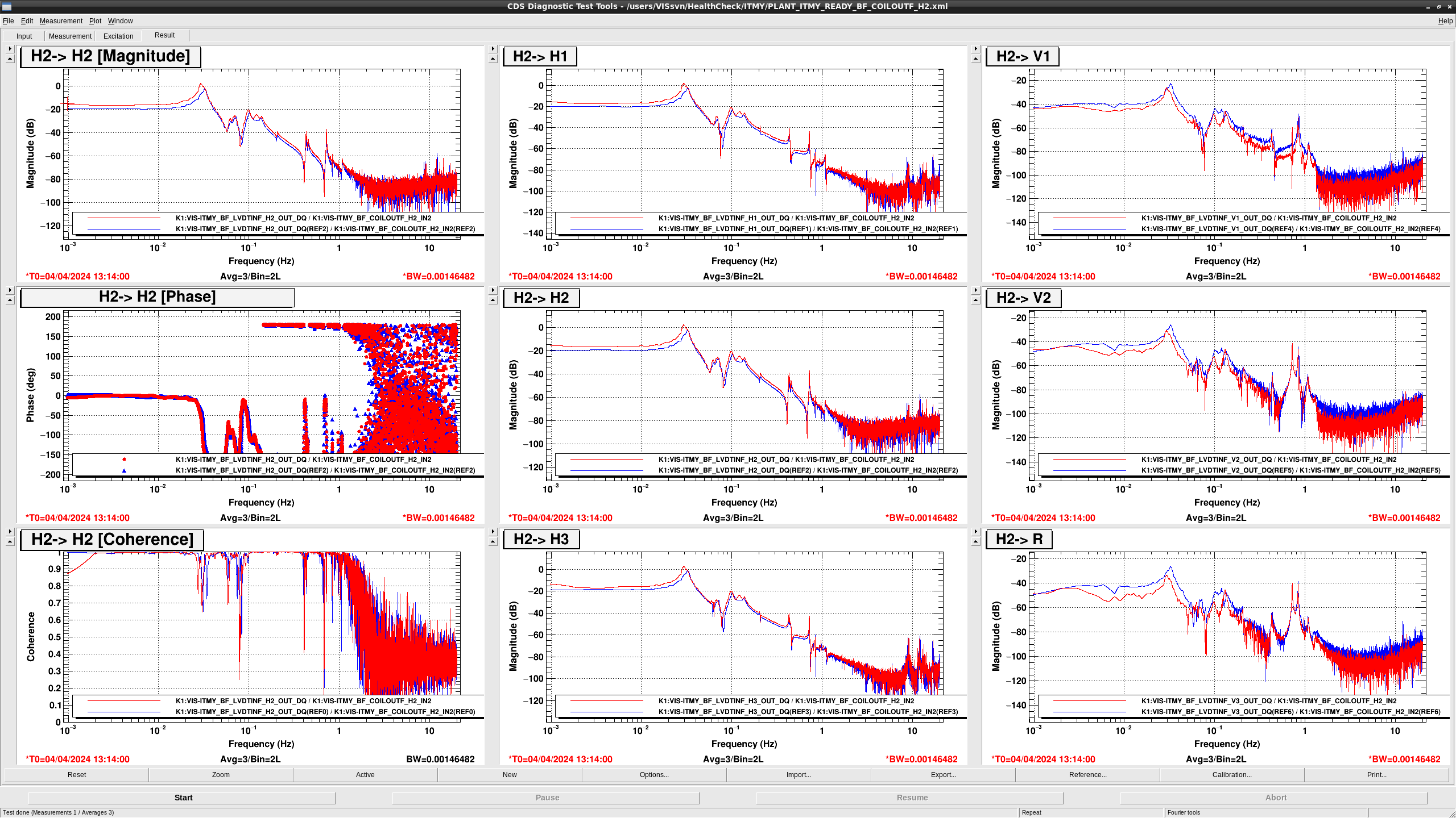
- COIL H2 -> LVDT H2 seems to be healty.
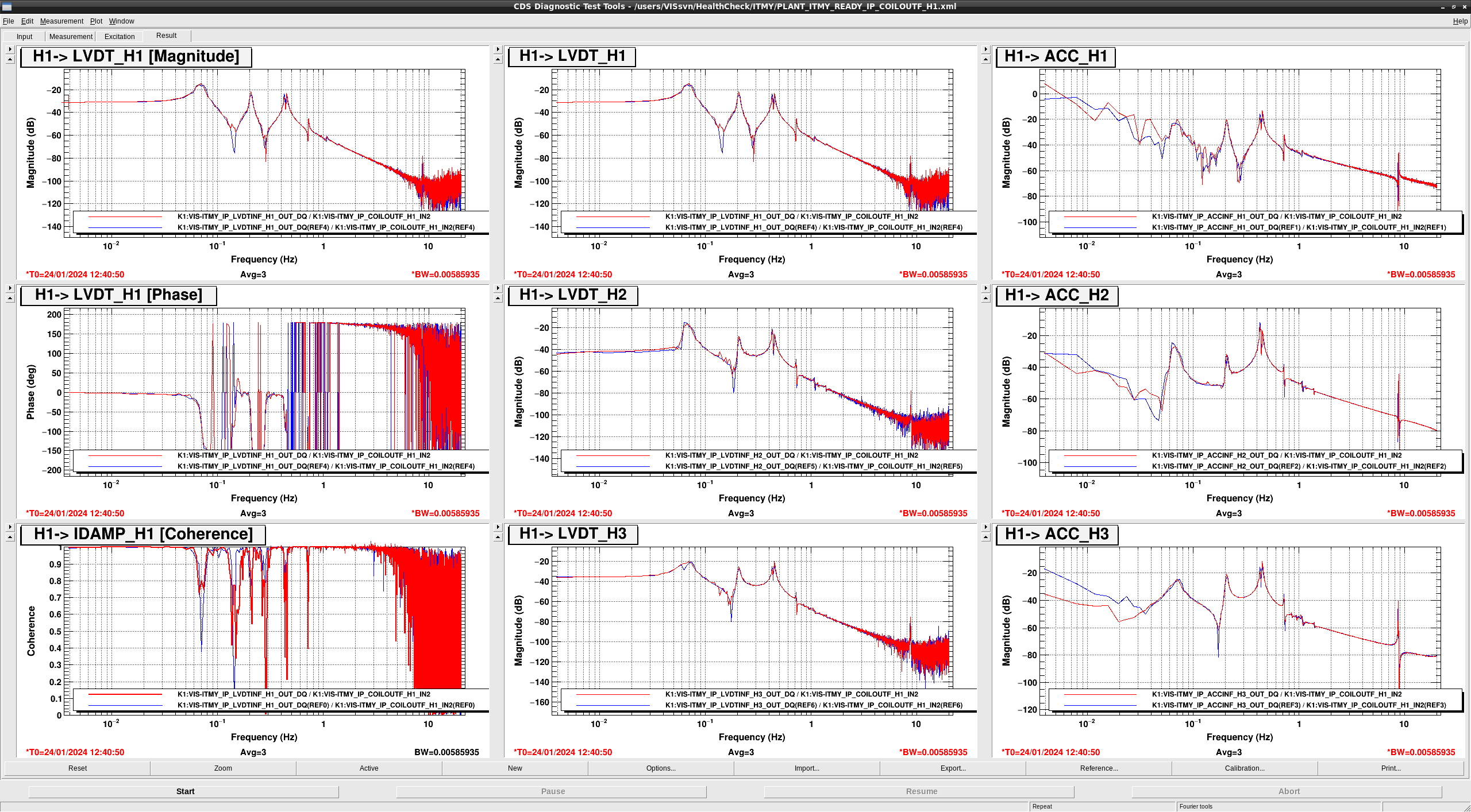
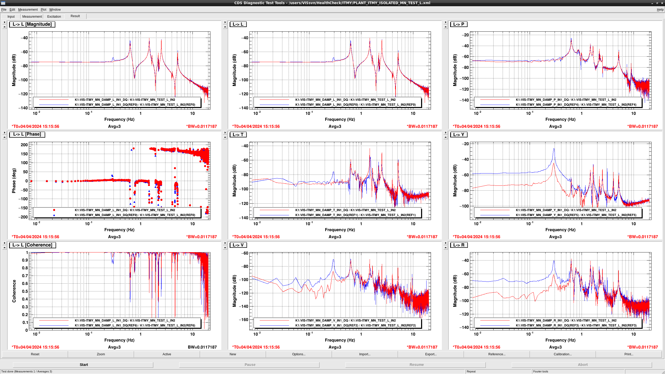
- There is the dip at 50 - 60 mHz in TEST L -> IDAMP L, There is the dip at 70 mHz in TEST Y -> IDAMP Y. The overall gain above 0.1 Hz in TEST Y -> IDAMP Y became larger.
- The resonance peak at 63 mHz seems to be damped. The overall gain of TEST {L, Y} -> IDAMP {L, Y] became larger.
- The shape of TEST Y -> IDAMP T below 0.2 Hz seems to be changed due to the change of the LVDT and ACC T responce below 0.2 Hz.
## GAS
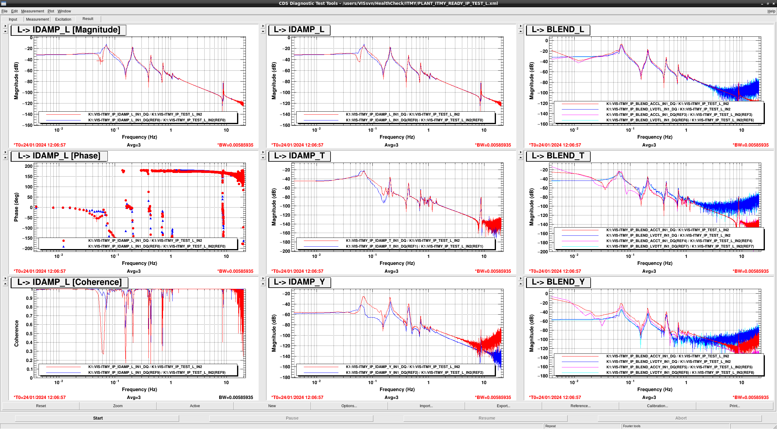
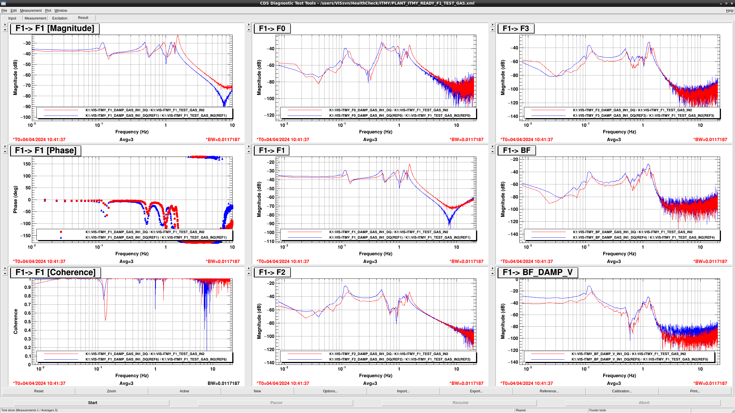
- In F0 -> F0 and F1 -> F1, all of the resonance frequencies were shifted to the higher side.
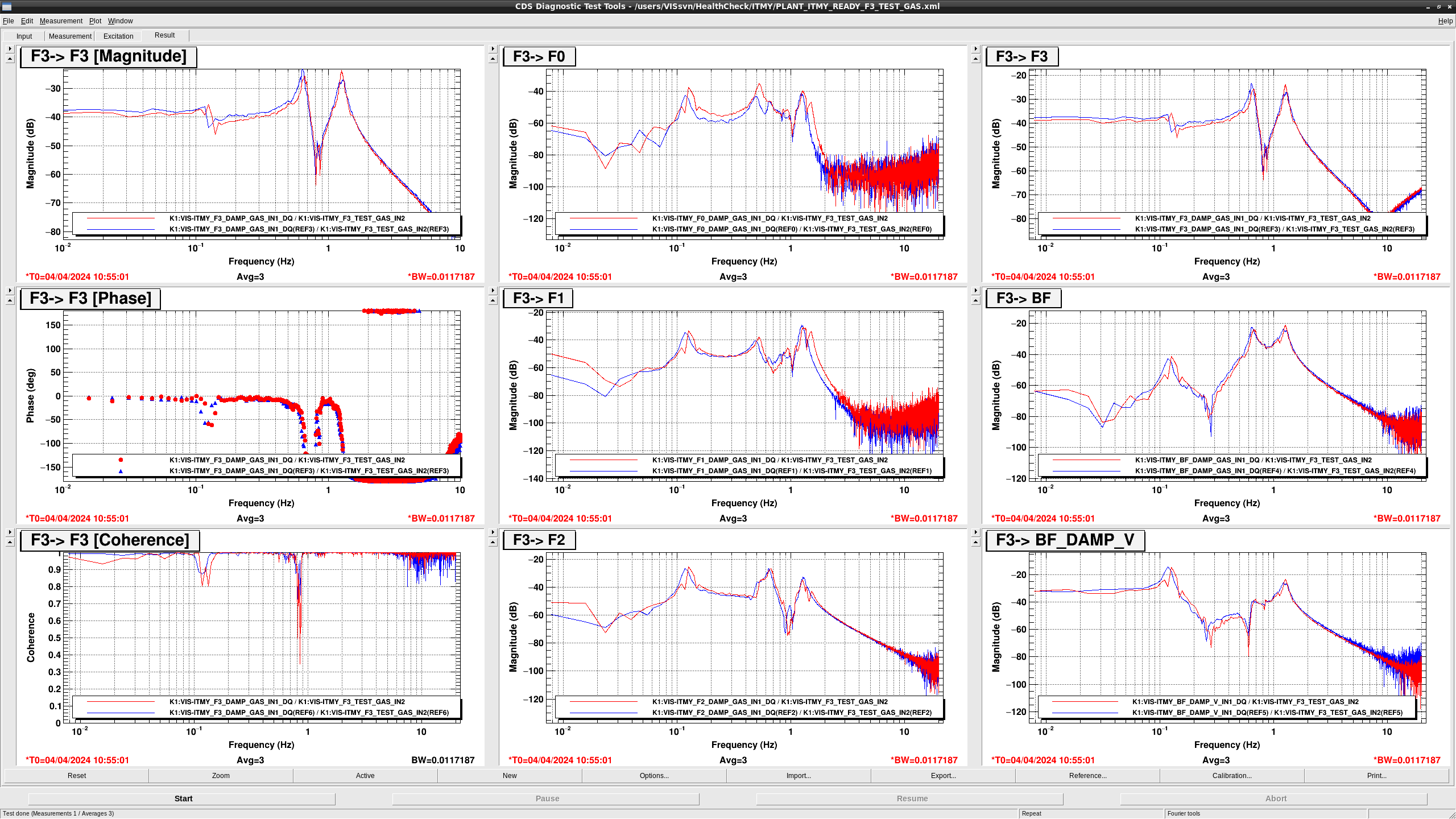
- in F3 -> F3, 0.2 Hz peak appeared and the 0.75 Hz and 1.3 Hz peak shifted to the lower side
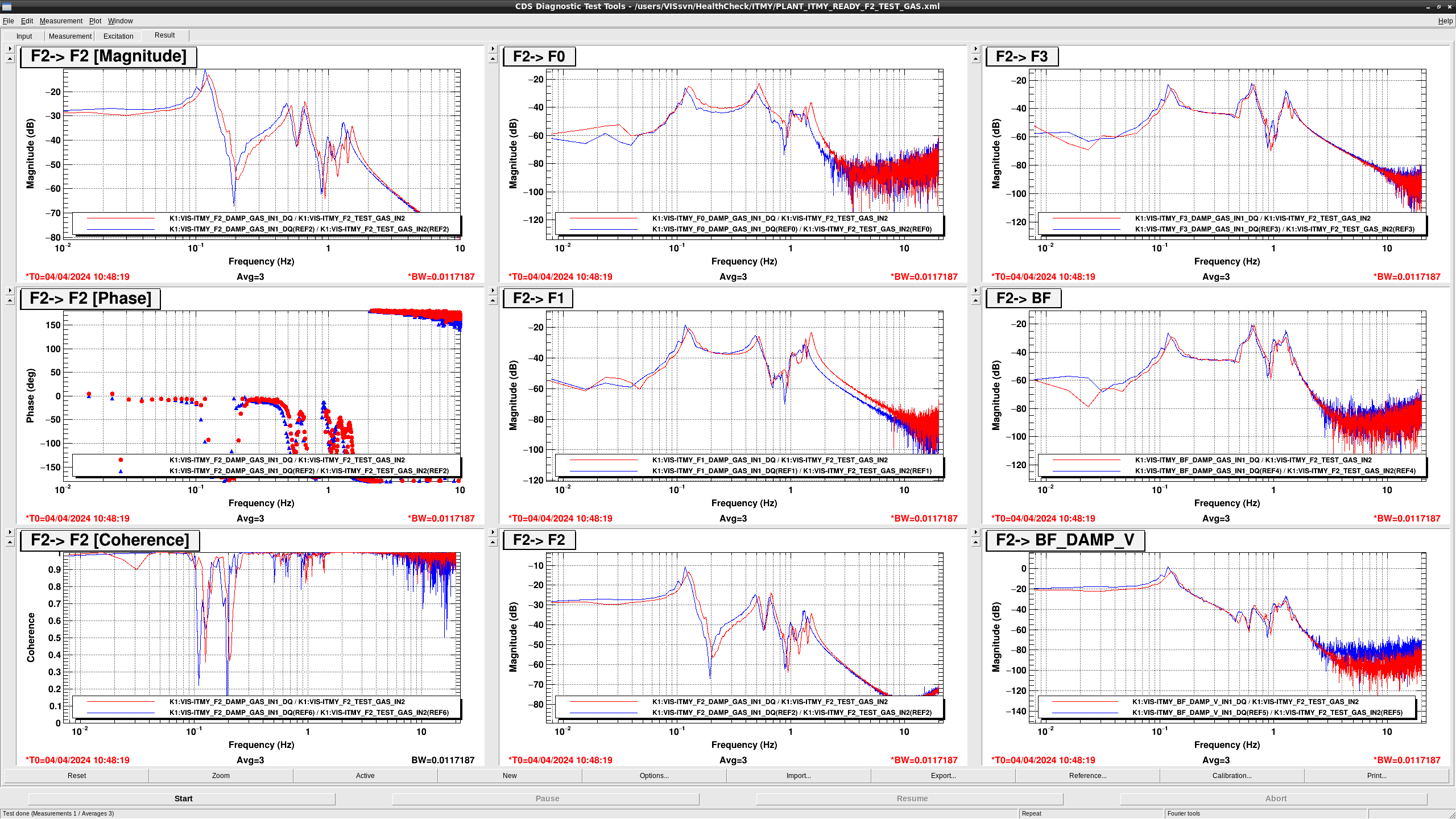
- F2 seem not to work. However the F2 control can be engaged. Therefore F2 seem to stack in the READY state. So We need to offload it.
- in BF -> BF, the 0.65 Hz peak and 1.3 Hz peak shifted to lower and the Q of 1.3 Hz peak became larger. The peak at 0.2 Hz appeared.
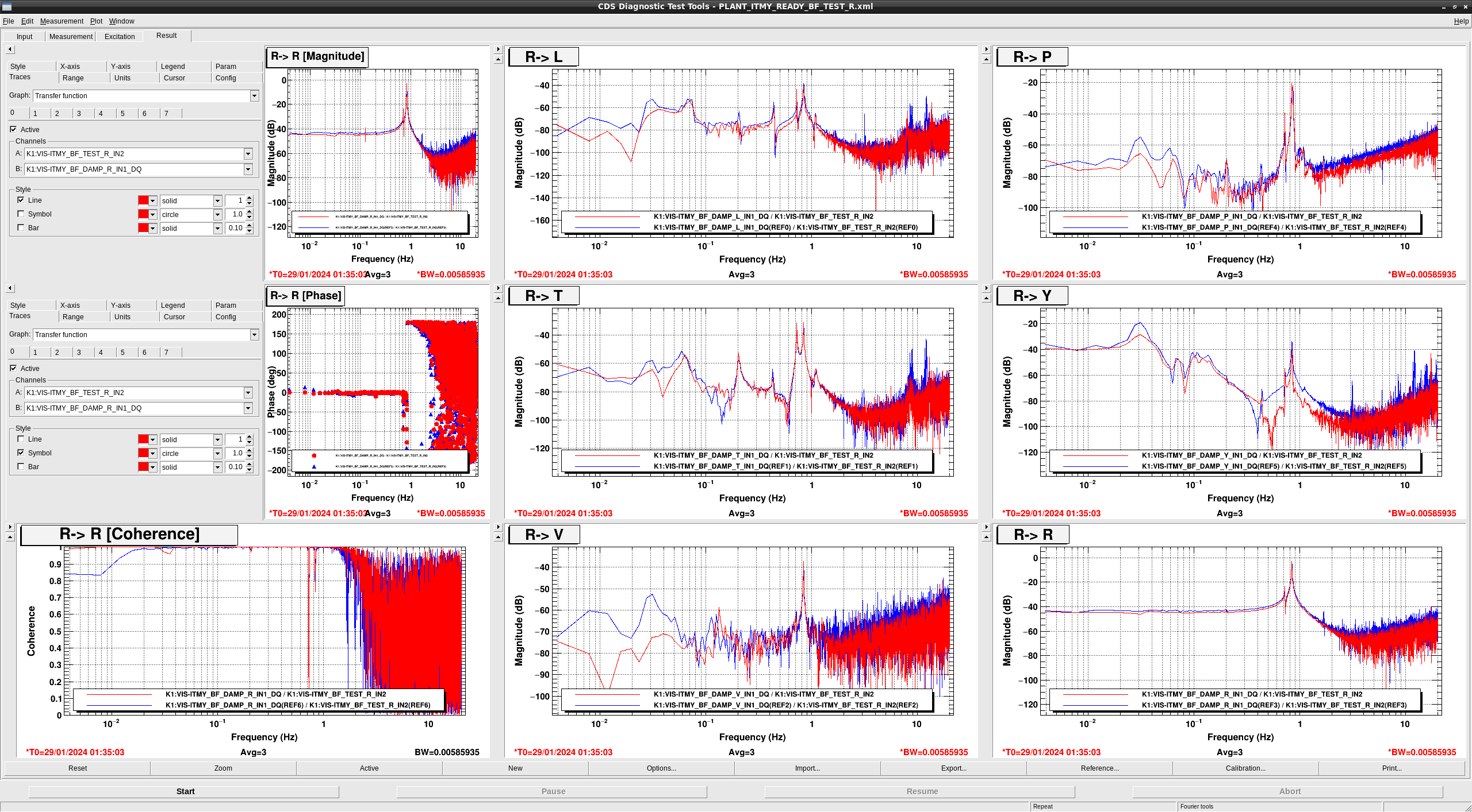
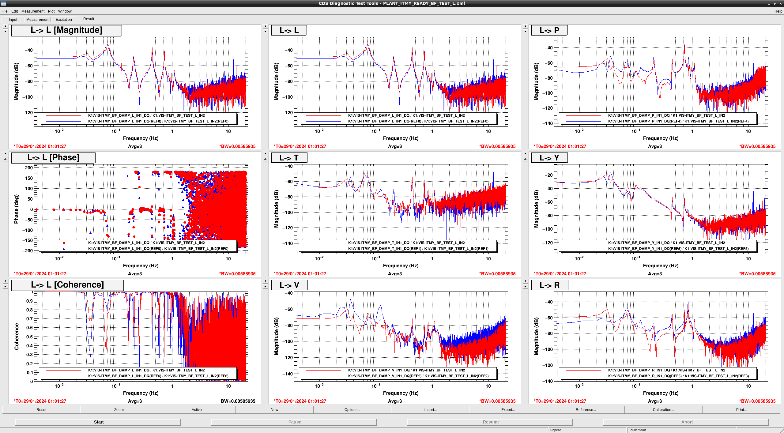
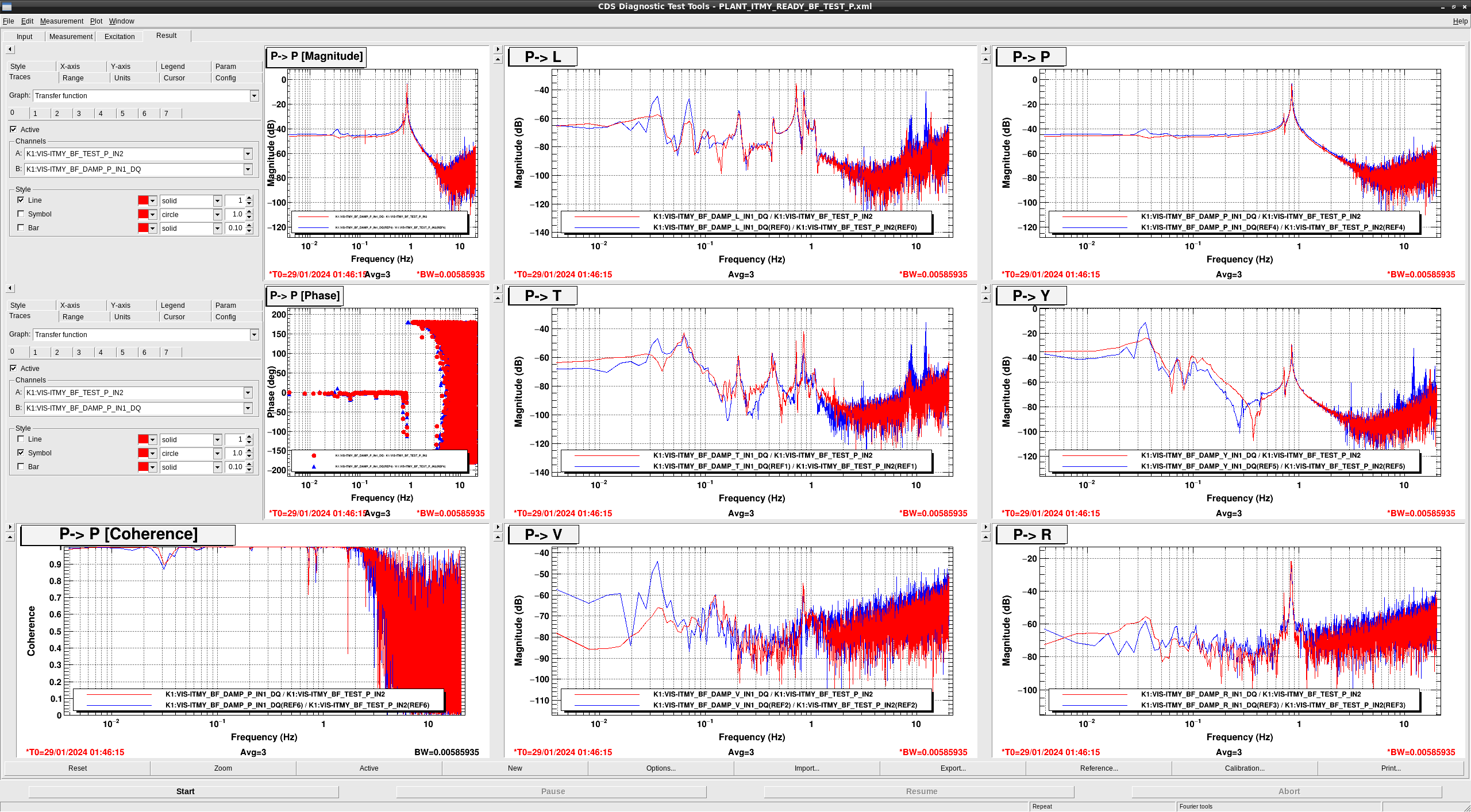
## BF
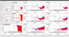
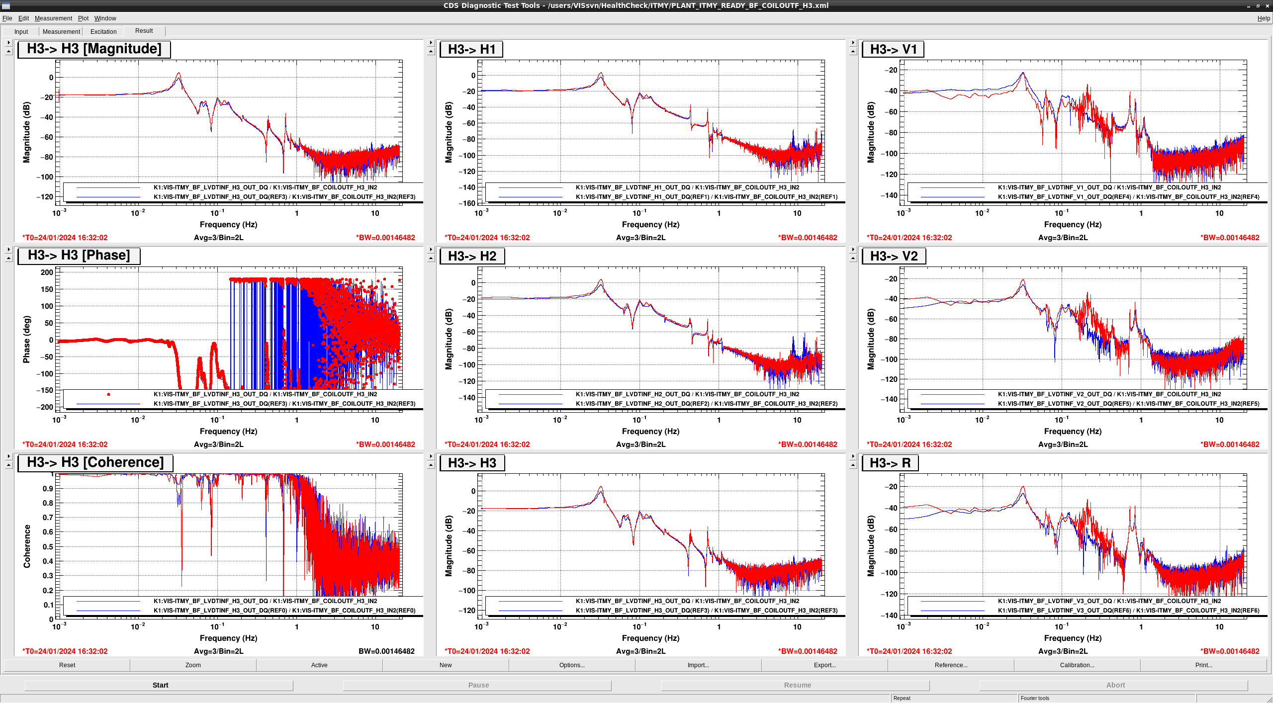
- The peak at 0.2 Hz COIL H{1,2,3} -> LVDT V{1, 2, 3} appeared.
- In COIL V1 -> LVDT V1, V2, V3, the resonance frequencies shifted from 0.12 Hz to 0.2 Hz and the DC gains became lower -10dB.
- In COIL V2 -> LVDT V1, V2, V3, the resonance frequencies shifted from 0.12 Hz to 0.2 Hz and the DC gains became lower -10dB.
- In COIL V3 -> LVDT V1, V2, V3, the resonance frequencies shifted from 0.12 Hz to 0.2 Hz and the DC gains became lower -10dB.
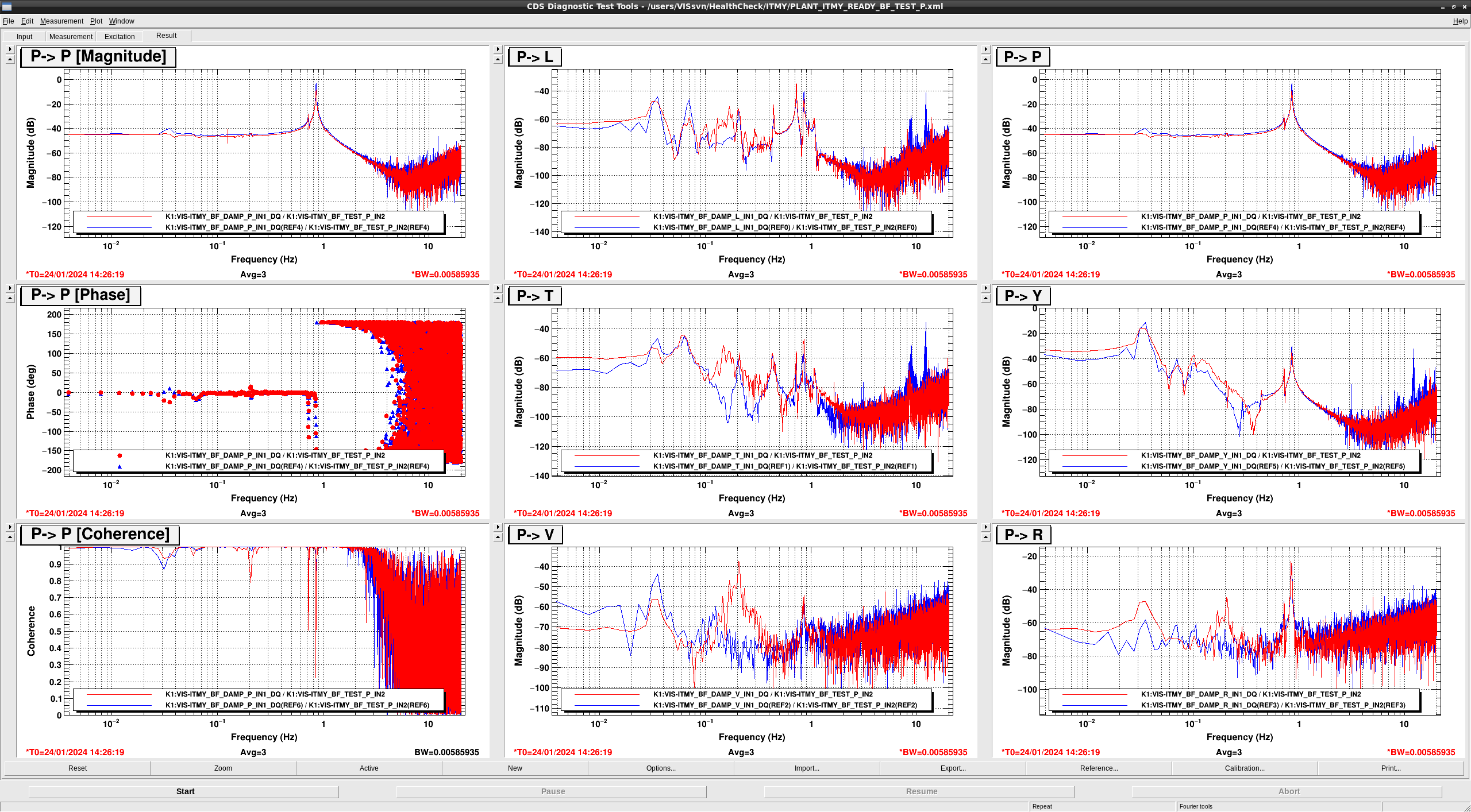
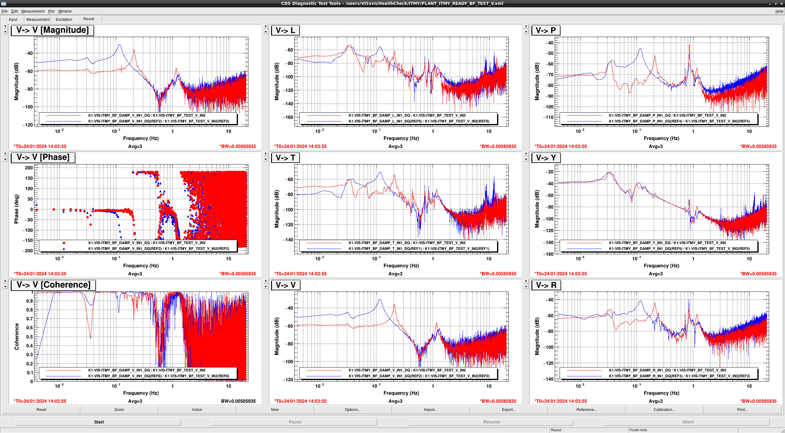
- In TEST L, T -> DAMP V, the resonance frequencies shifted from 0.12 Hz to 0.2 Hz.
- In TEST V -> DAMP V,P,R the resonance frequencies shifted from 0.12 Hz to 0.2 Hz and the DC gains became lower -10dB.
- The peak at 0.2 Hz in TEST R, P, Y -> DAMP V appeared.
- The peak at 0.2 Hz in TEST Y -> DAMP P,R appeared. and the gain below 0.3 Hz in TEST Y -> DAMP R became larger.
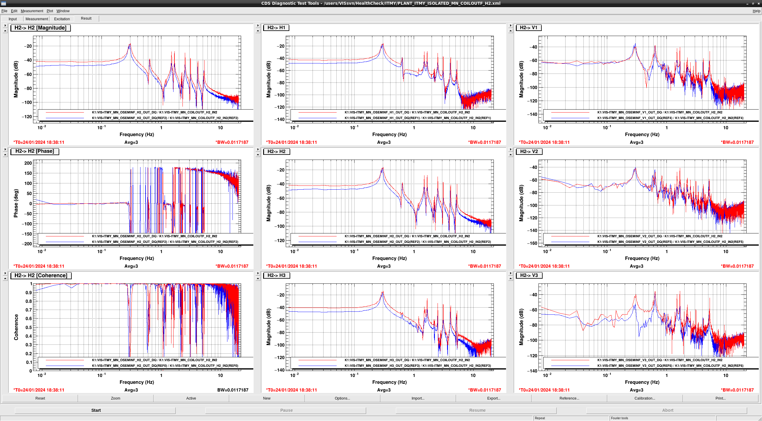
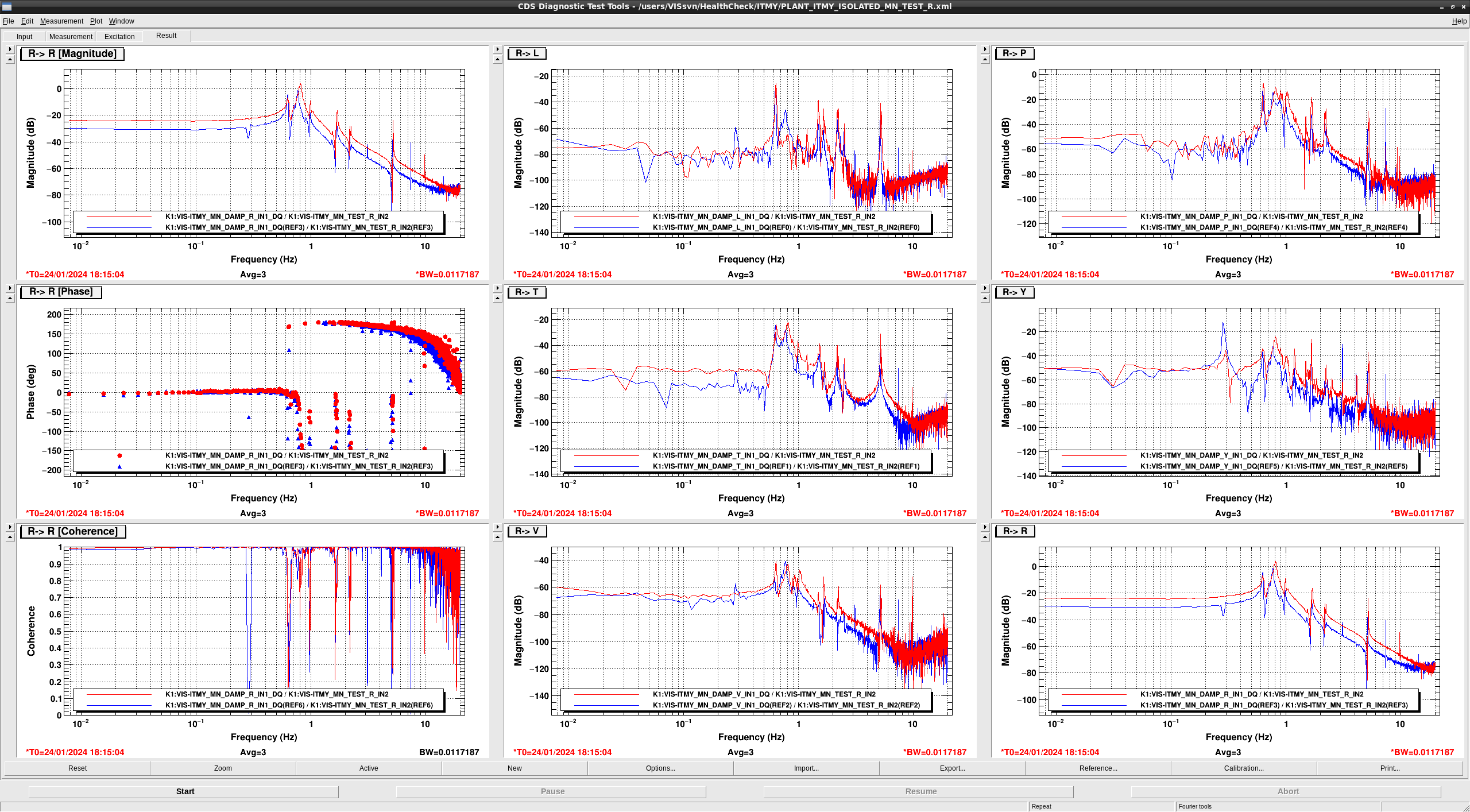
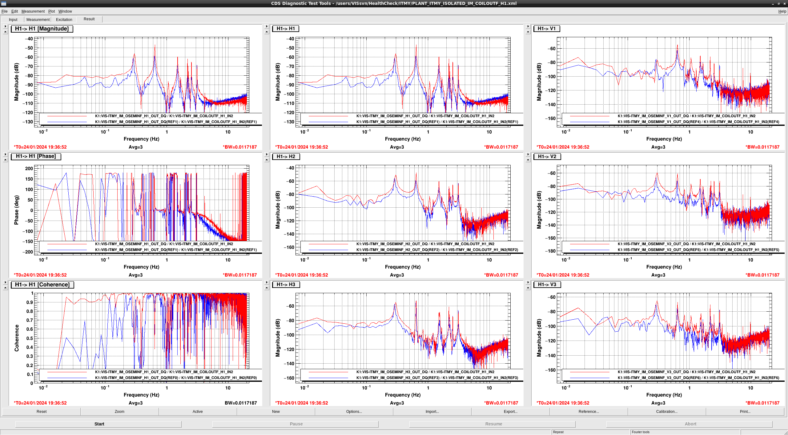
## MN seems to be healthy
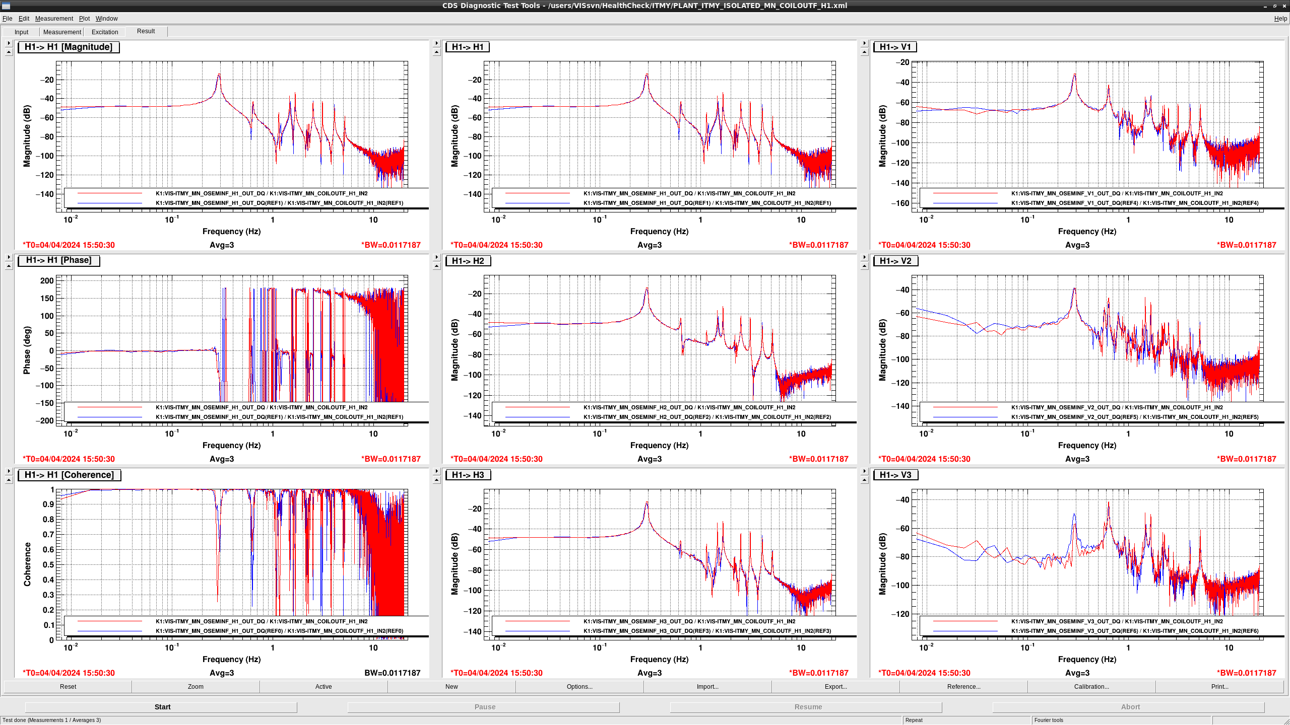
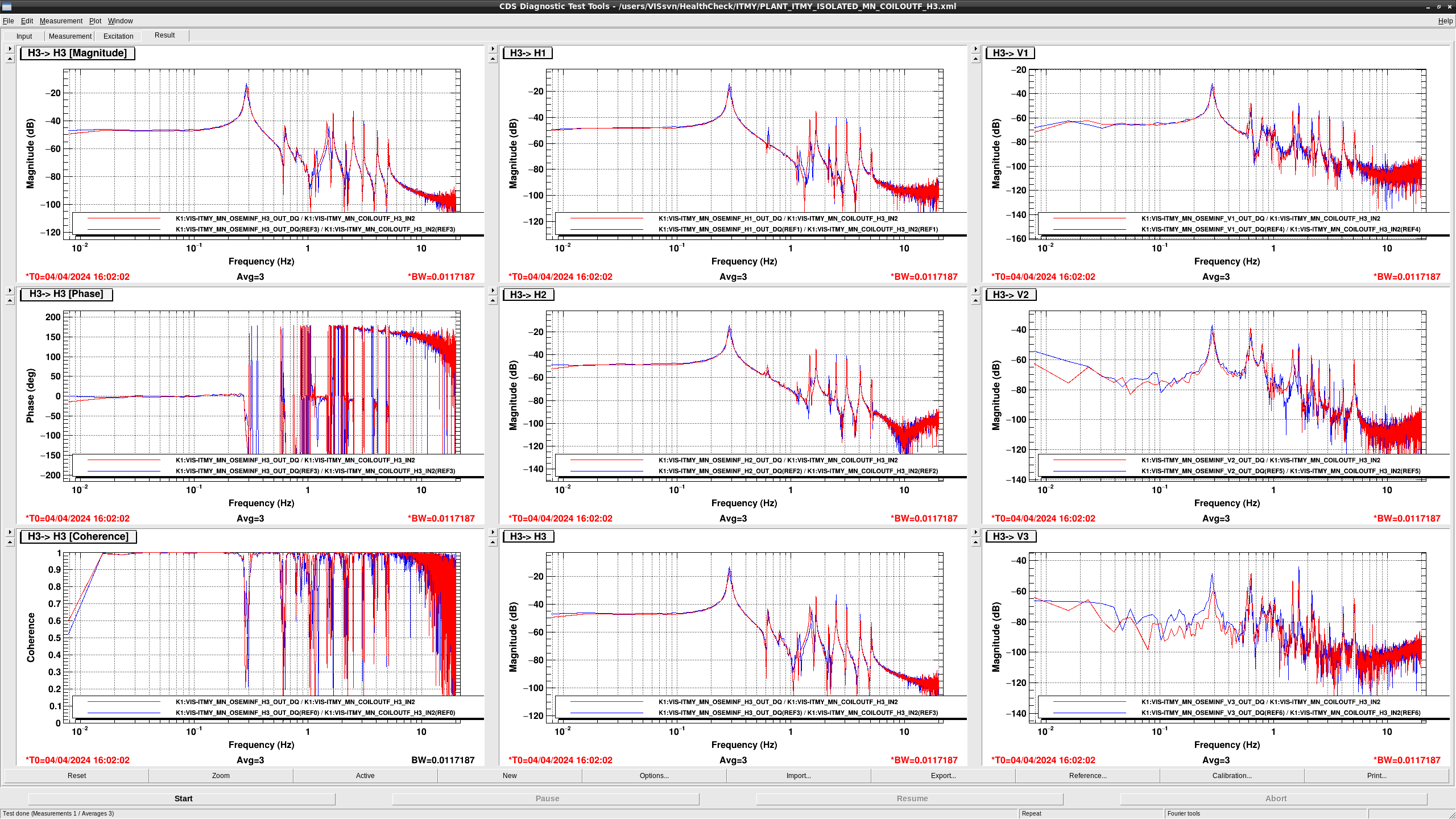
- The overall gain in COIL H1 -> OSEMINF H{1,2,3} became larger +10dB maybe due to the change of the photosenor gain by temeperature change.
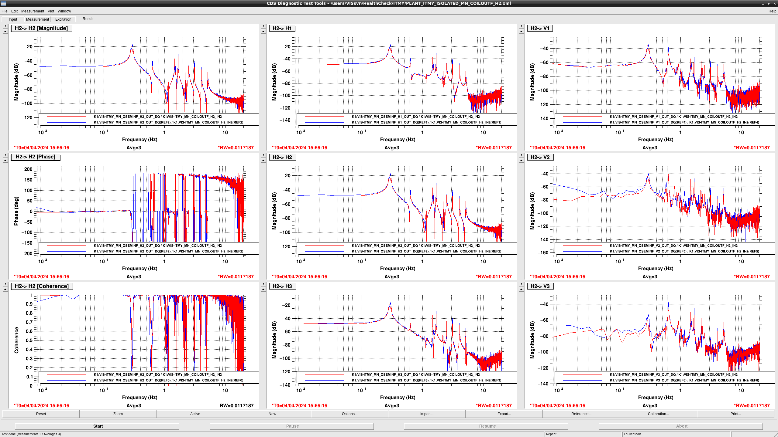
- The overall gain in COIL H2 -> OSEMINF H{1,2,3} became larger +10dB.
- The overall gain in COIL H3 -> OSEMINF H{1,2,3} became larger +10dB.
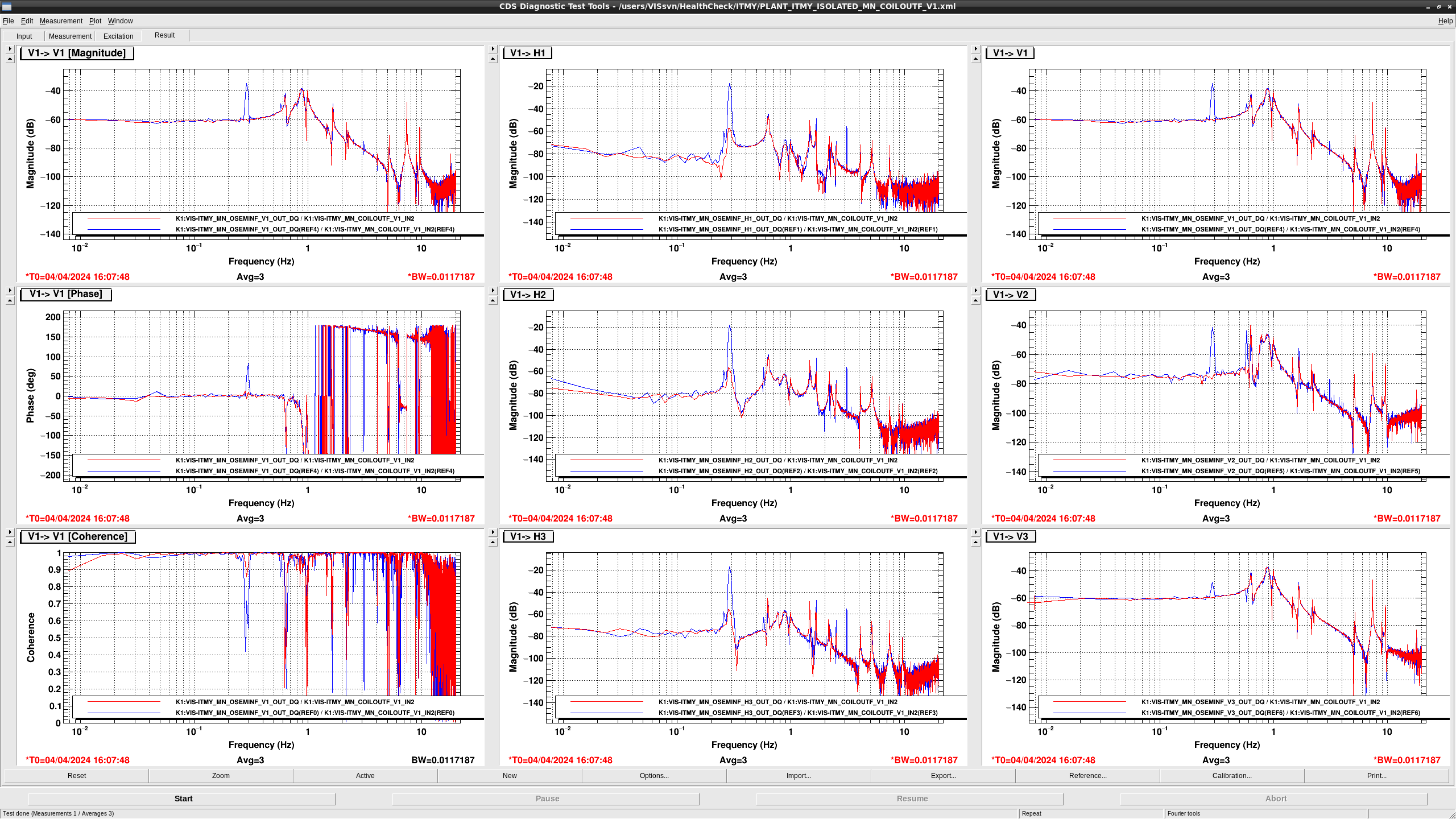
- The overall gain in COIL V1 -> OSEMINF V{1,2,3} became larger +10dB and the peak at 0.3 Hz disappeared in COIL V1 -> OSEMINF V{1,2,3}.
- the peaks at 0.3 Hz were damped in COIL V1 -> OSEMINF H{1,2,3}.
- The overall gain in COIL V2 -> OSEMINF V{1,2,3} became larger +10dB and the peak at 0.3 Hz disappeared in COIL V2 -> OSEMINF V{1,2,3}.
- the peaks at 0.3 Hz became smaller in COIL V2 -> OSEMINF H{1,2,3}.
- The overall gain in COIL V3 -> OSEMINF {H,V}{1,2,3} became larger +10dB and the peak at 0.3 Hz disappeared in COIL V3 -> OSEMINF V{1,2}.
- the peaks at 0.3 Hz became smaller in COIL V3 -> OSEMINF H{1,2,3}.
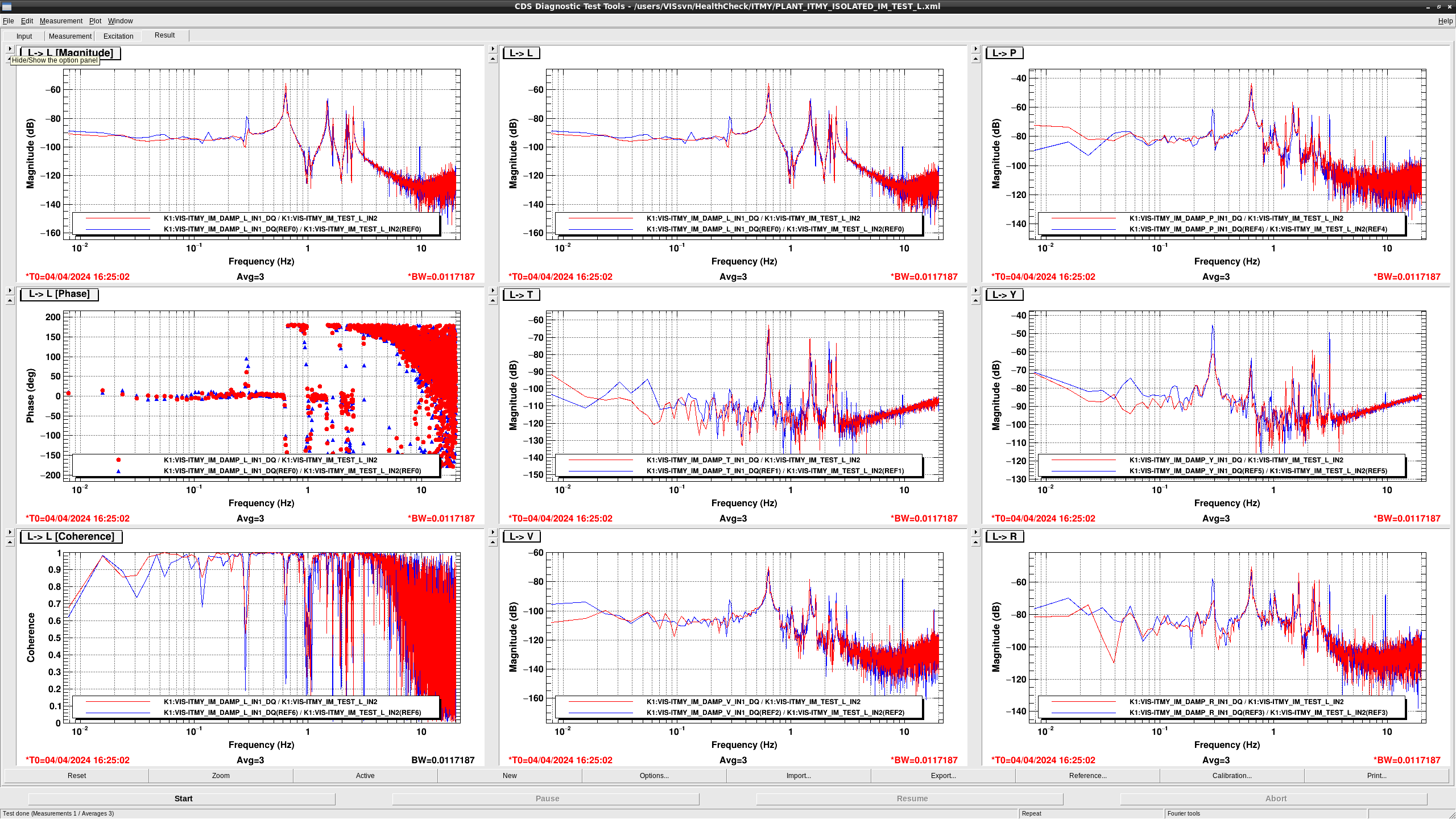
- The overall gain in TEST L -> DAMP L, P became larger and the gain above 0.3 Hz in TEST L -> DAMP {L, T, V, R, P, Y} became larger.
- the pole at 0.3 Hz and the zero at 0.25 Hz became larger in TEST L -> DAMP T, V.
- The overall gain in TEST T -> DAMP T, R, P became larger
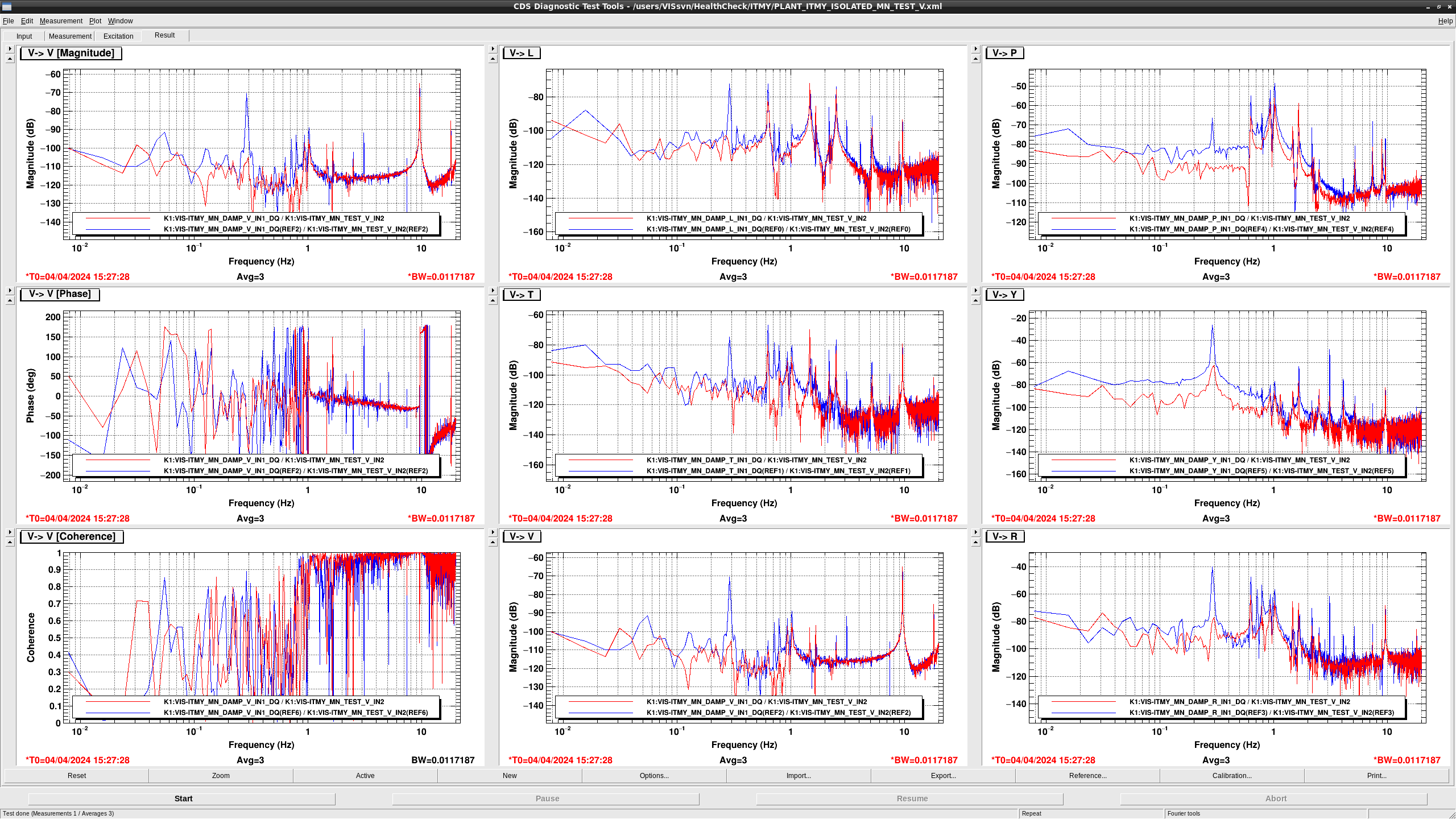
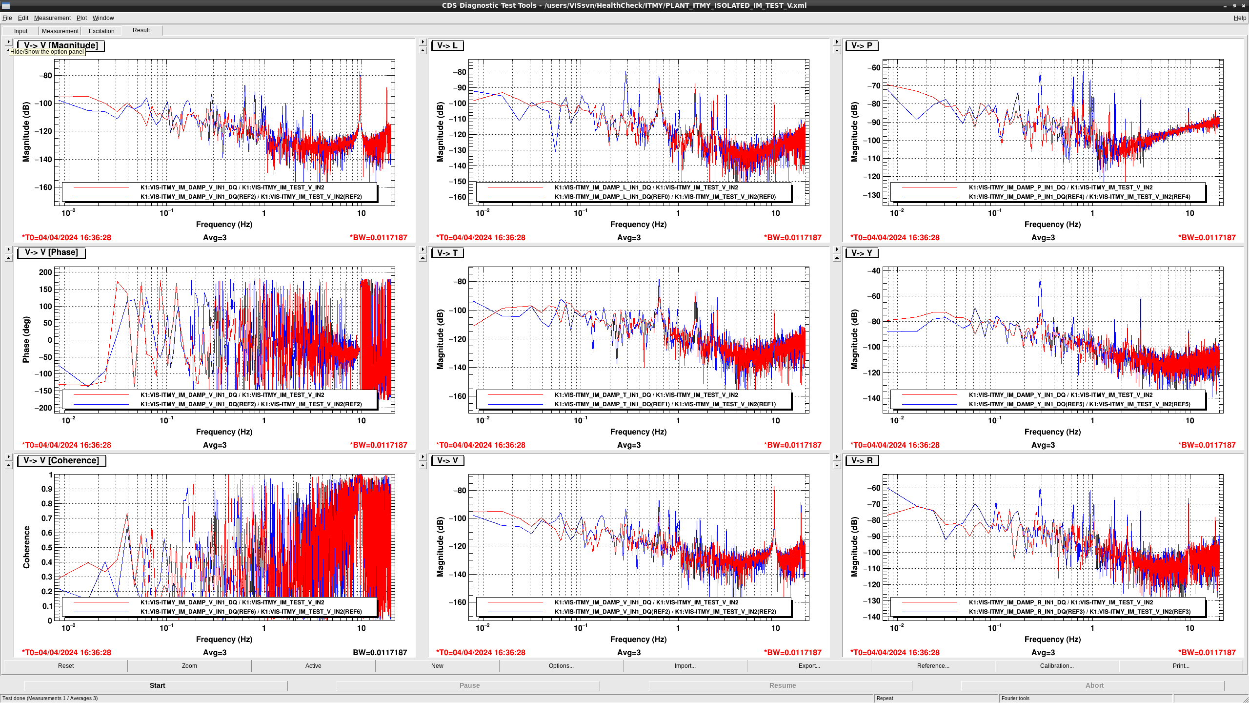
- The shapes of TF from TEST V to DAMP {L, T, V, R, P, Y} seem to be somehow difference but the coherence of TEST V -> DAMP V was improved above 0.3 Hz. So they may be fine.
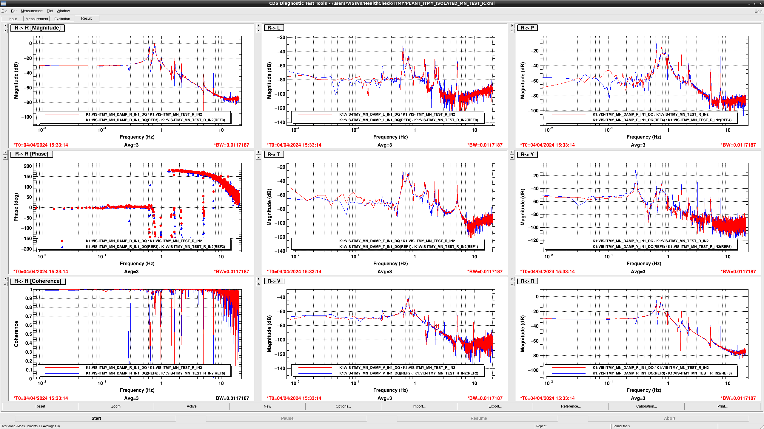
- The overall gain in TEST R -> DAMP T, V, R, P became larger.
- The overall gain became larger +10dB and the peak at 0.3 Hz disappeared in TEST P -> DAMP {L,T,V,R,P,Y}.
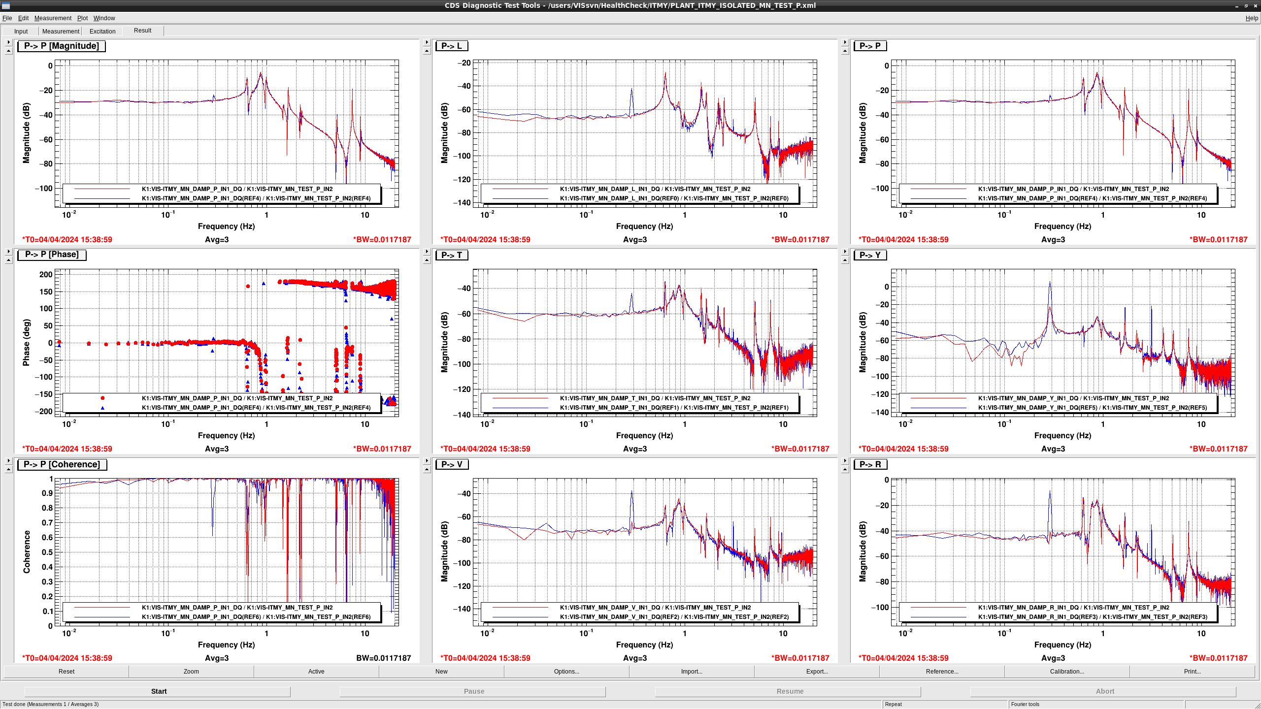
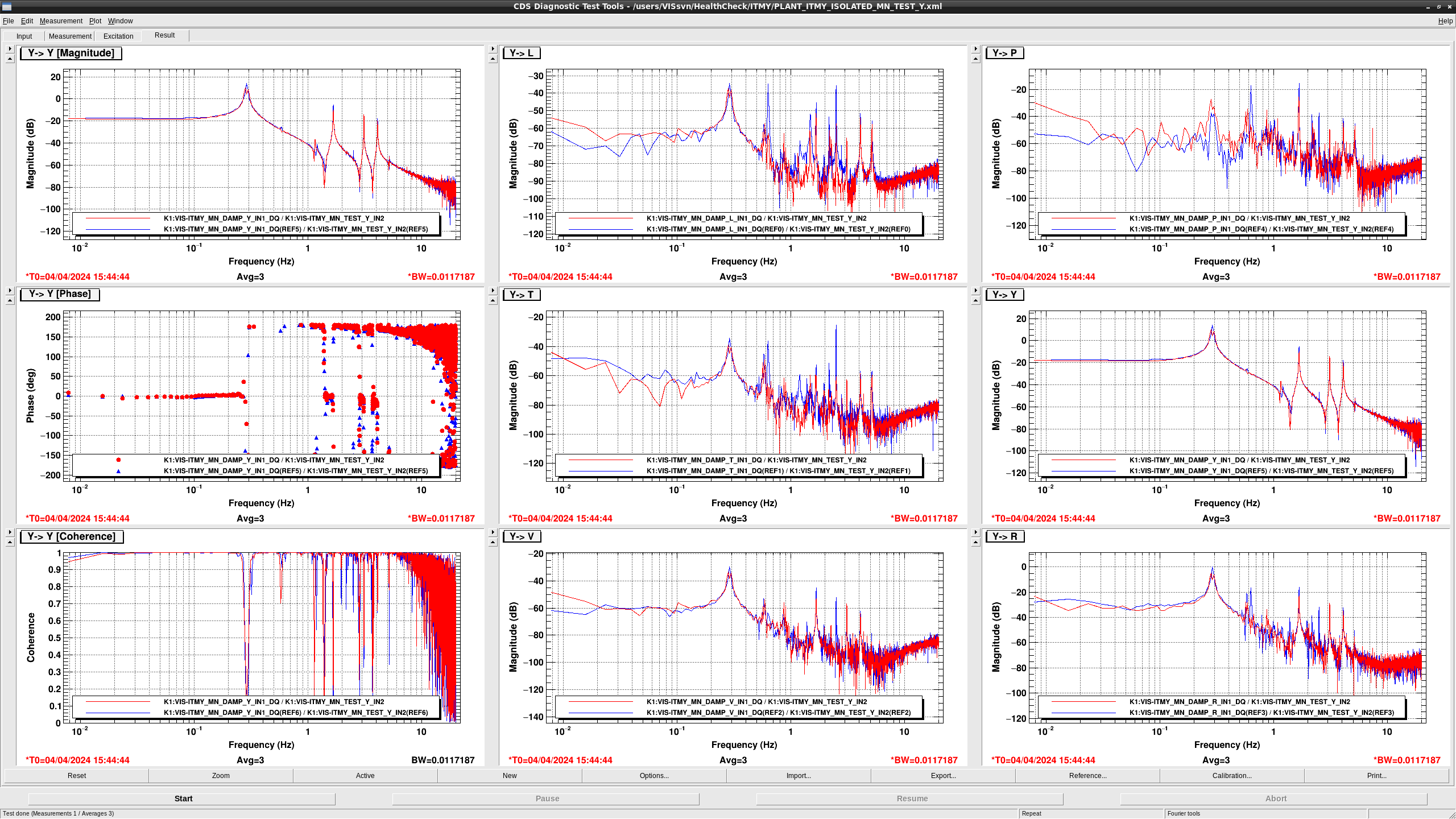
- The overall gain became larger in TEST Y -> DAMP {L,T,V,R,P,Y}.
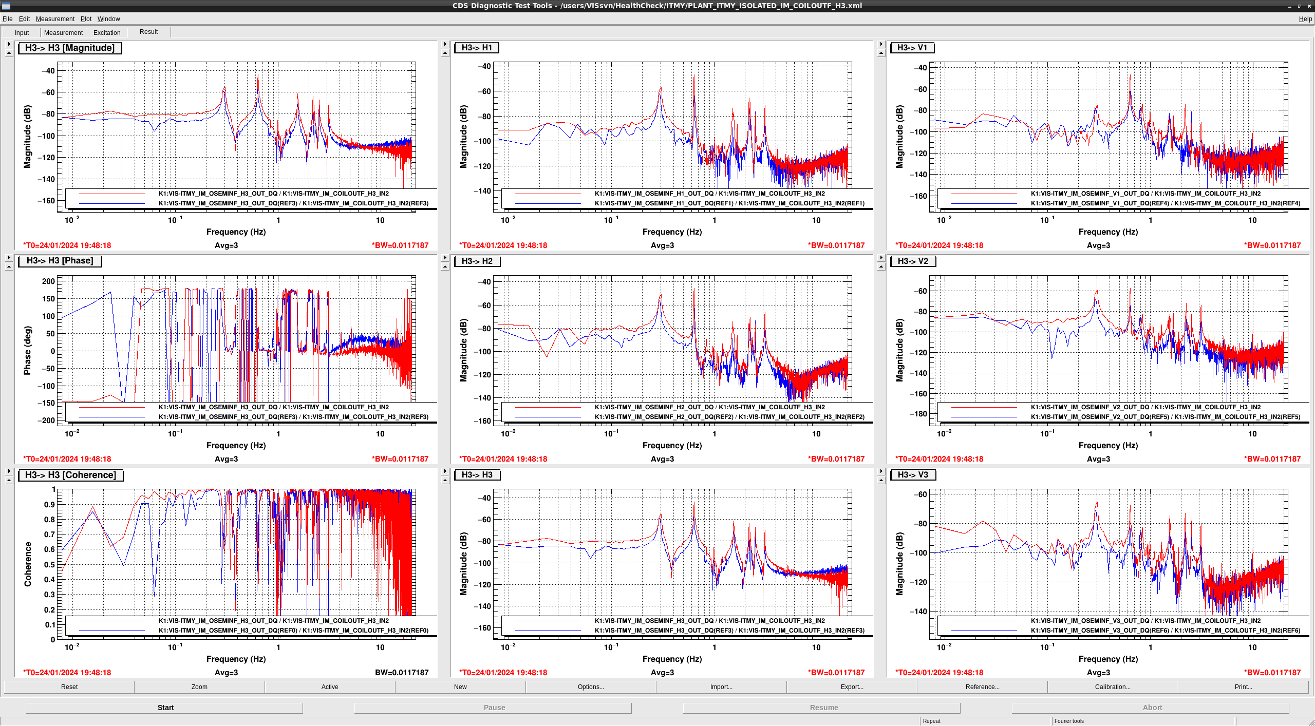
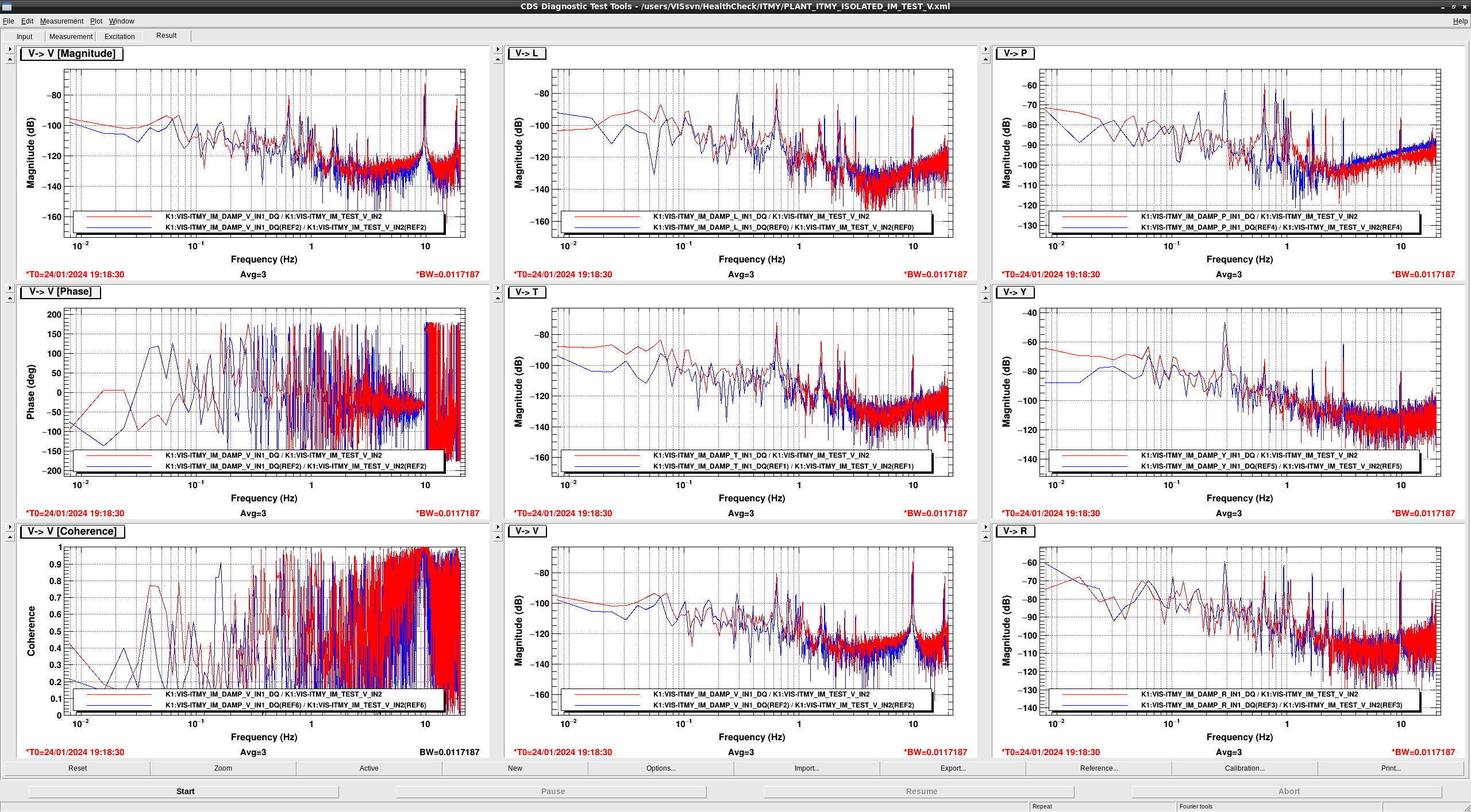
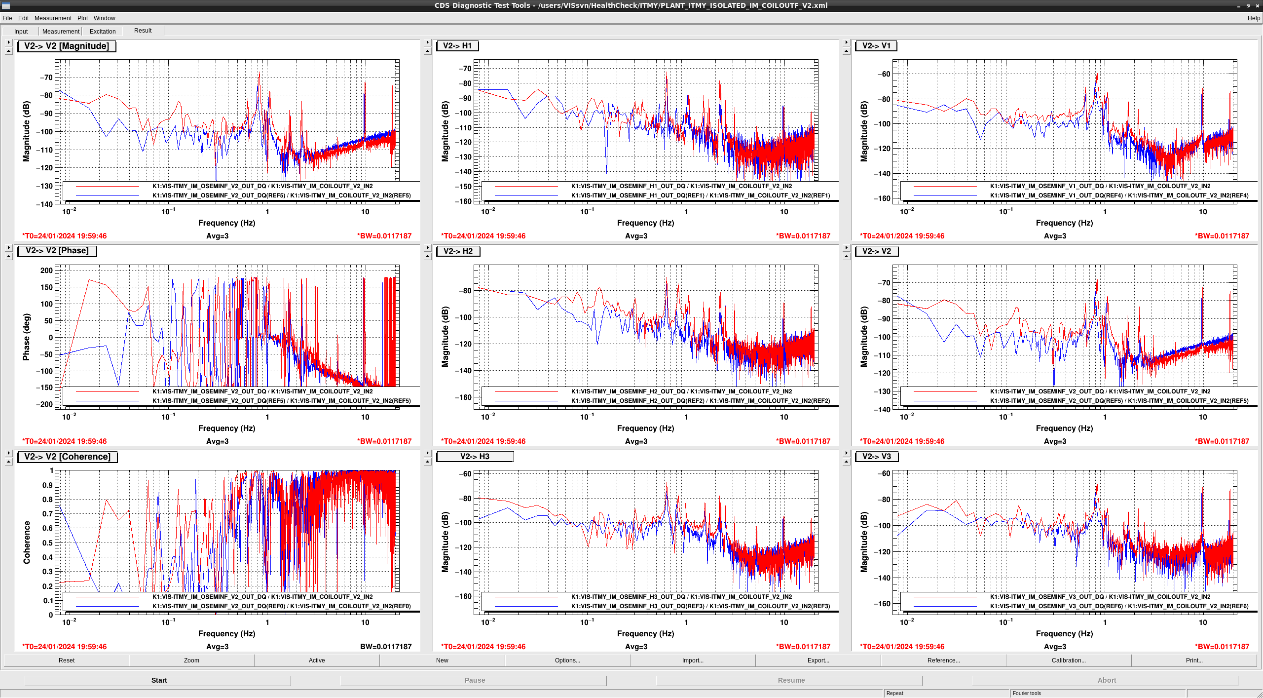
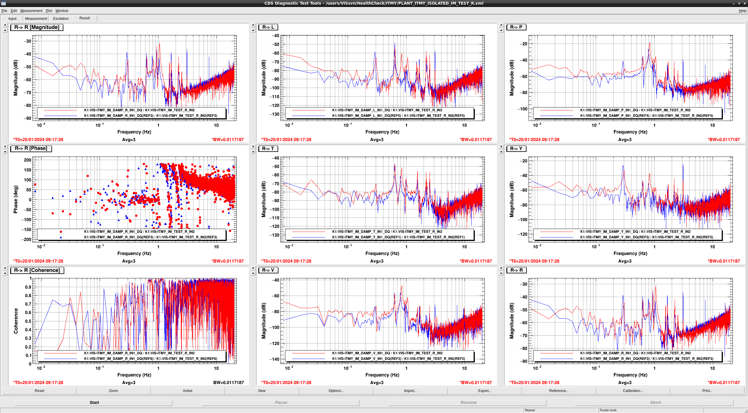
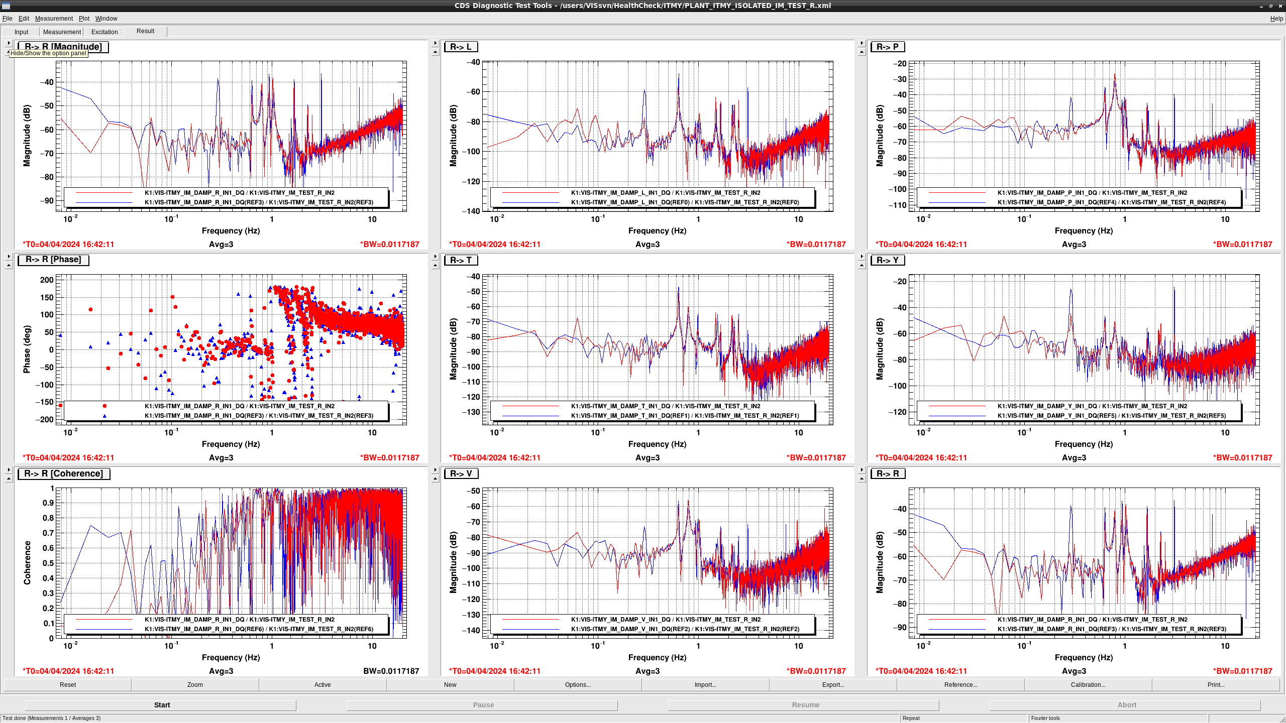
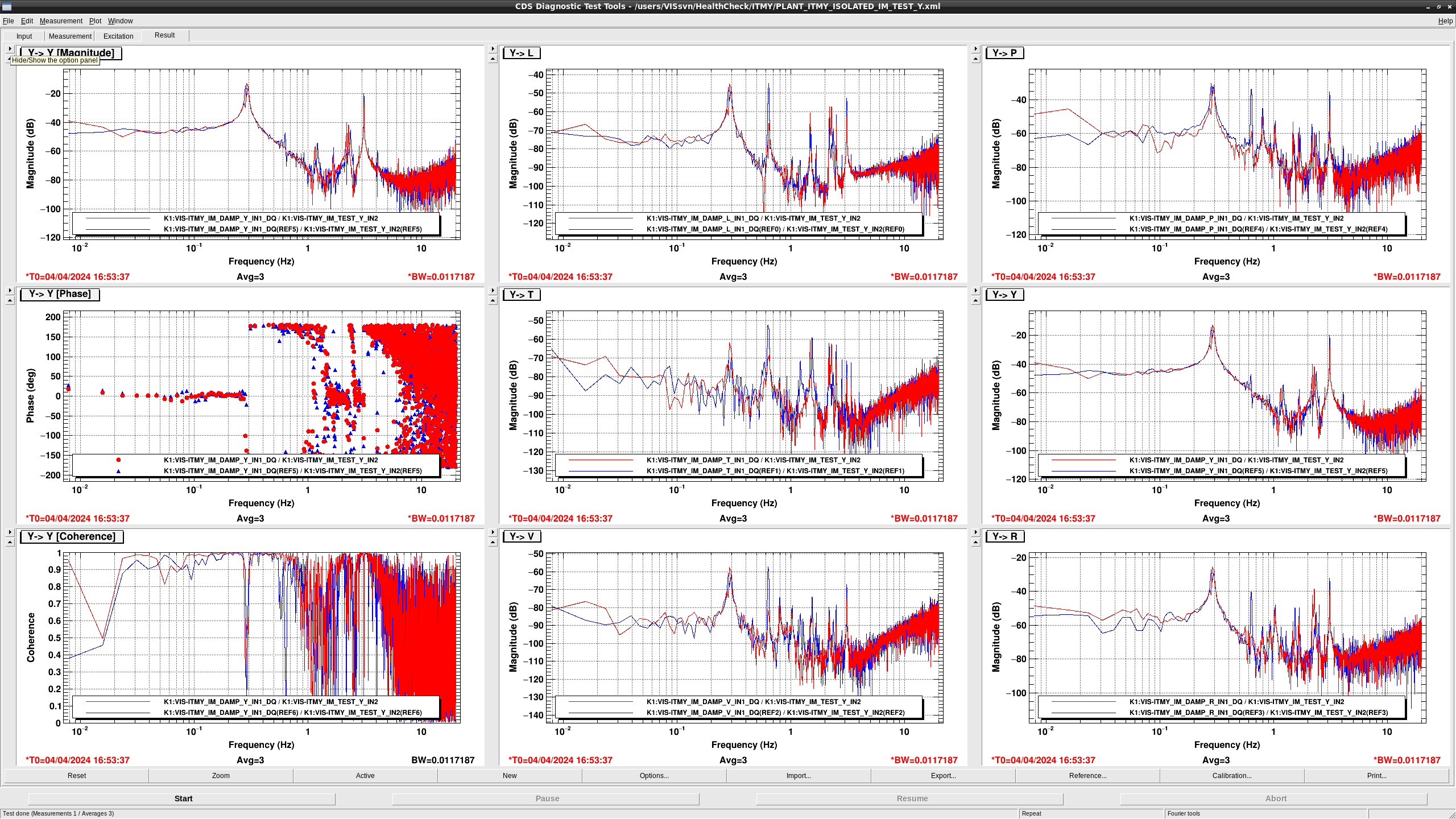
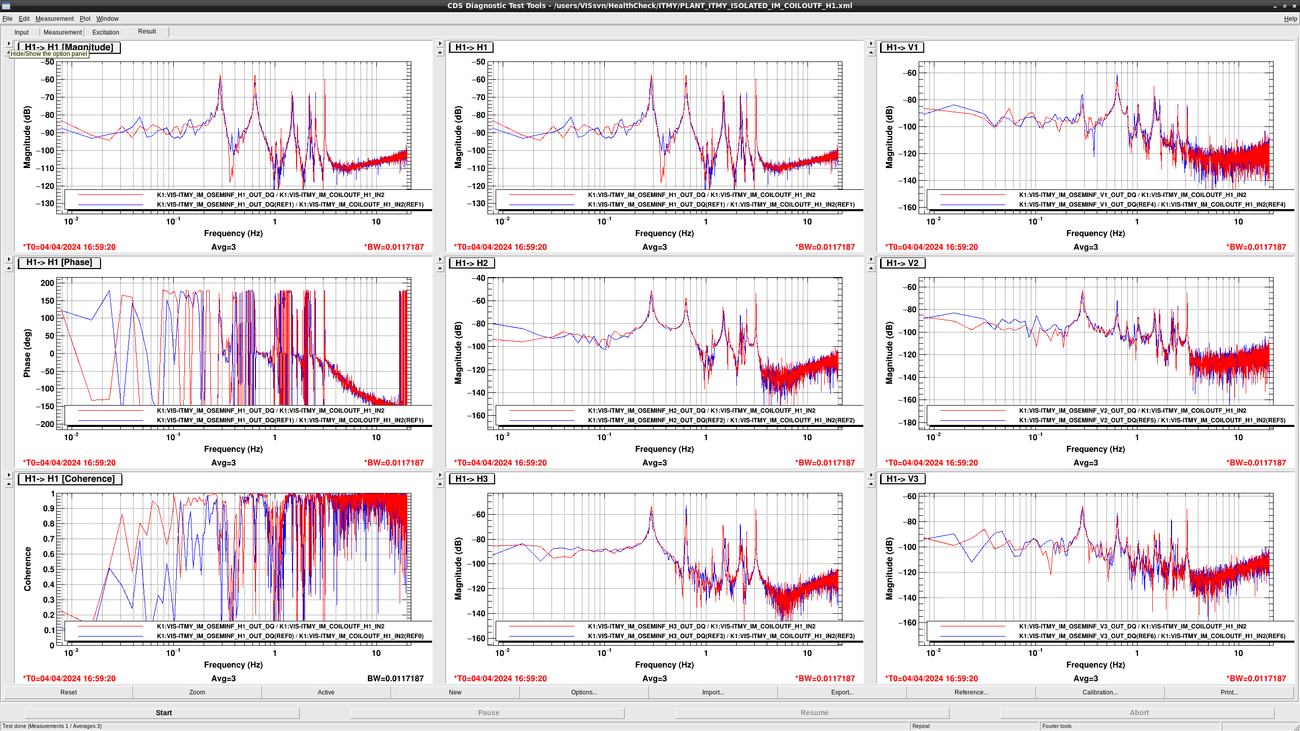
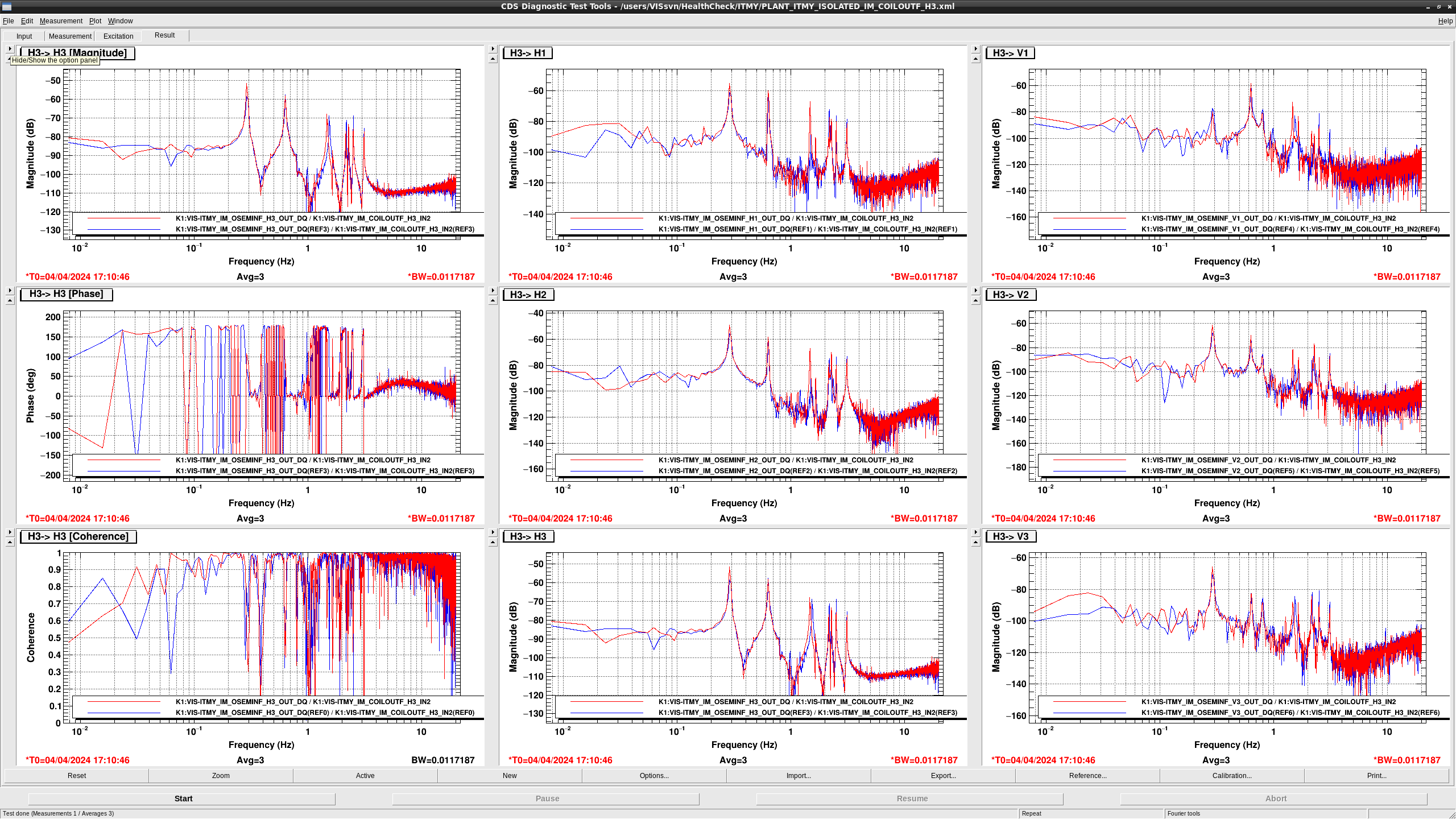
## IM seems to be healthy
- The overall gain in COIL H1 -> OSEMINF {H,V}{1,2,3} became larger.
- The overall gain in COIL H2 -> OSEMINF {H,V}{1,2,3} became larger.
- The overall gain in COIL H3 -> OSEMINF {H,V}{1,2,3} became larger.
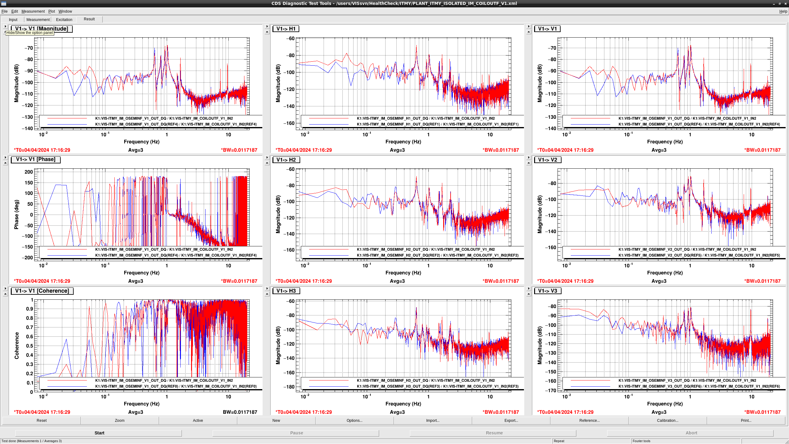
- The overall gain in COIL V1 -> OSEMINF {H,V}{1,2,3} became larger.
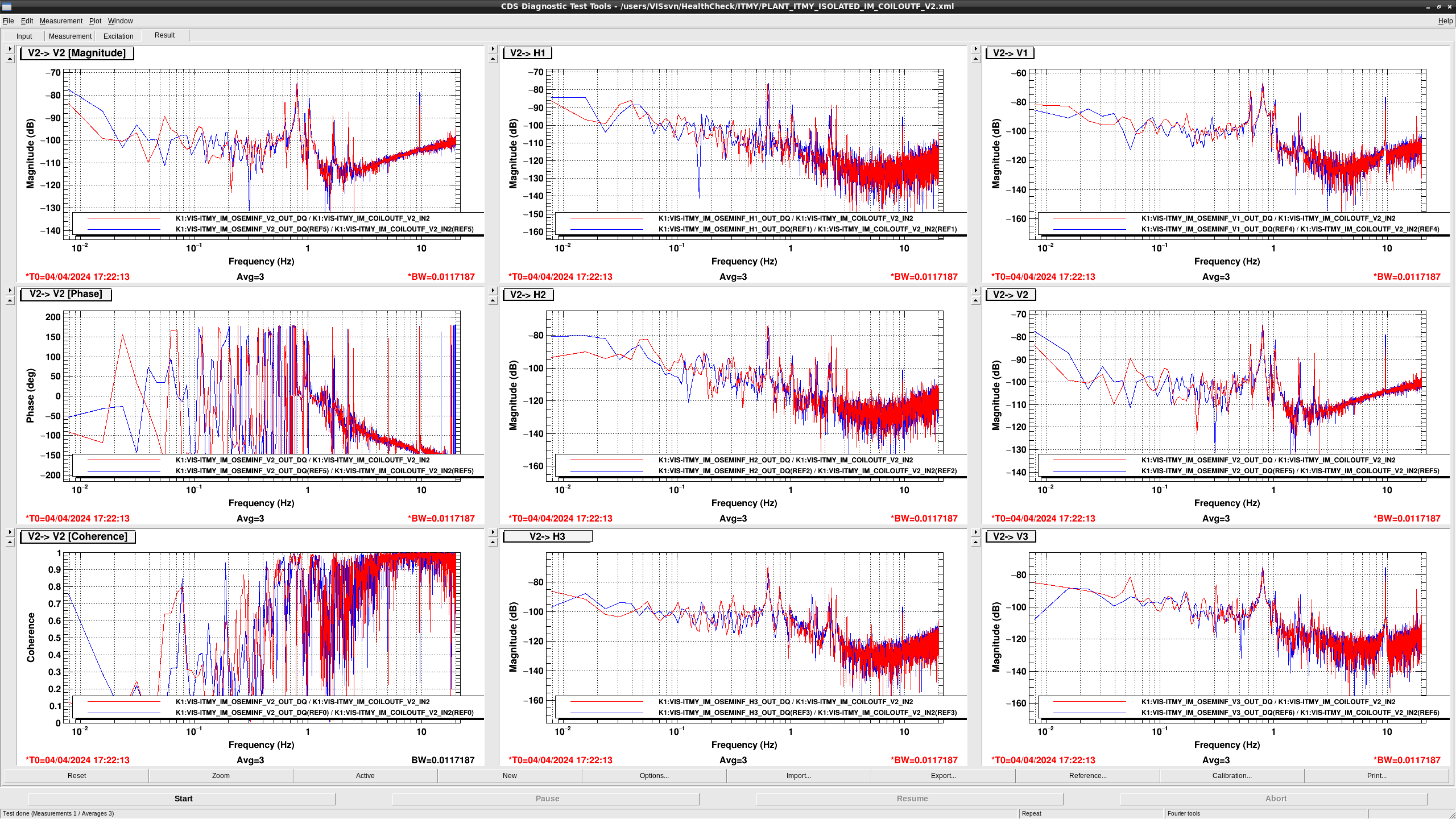
- The overall gain in COIL V2 -> OSEMINF {H,V}{1,2,3} became larger.
- The overall gain in COIL V2 -> OSEMINF {H,V}{1,2,3} became larger.
- The overall gain in TEST L -> DAMP {L,T,V,R,P,Y} became larger.
- The overall gain in TEST T -> DAMP {L,T,V,R,P,Y} became larger.
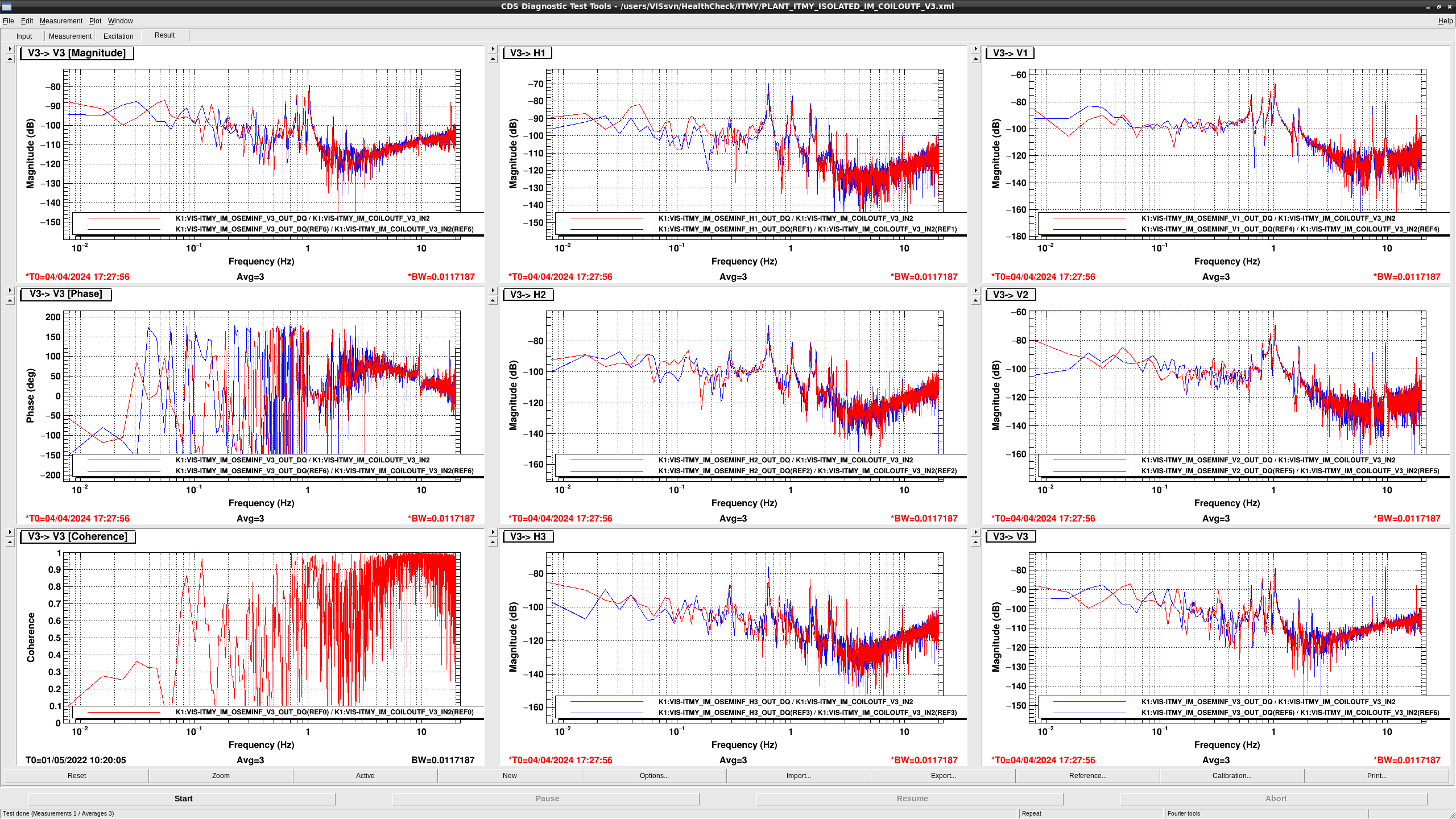
- TFs from COIL V3 seems to be healthy
- The overall gain in TEST P -> DAMP {L,T,V,R,P,Y} became larger.
- The overall gain in TEST Y -> DAMP {L,T,V,R,P,Y} became larger.
- The overall gain in TEST R -> DAMP {L,T,V,R,P,Y} became larger.

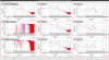


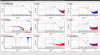
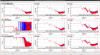

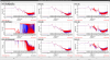
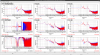


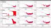
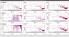
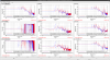
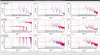
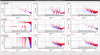
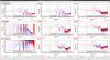
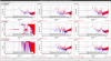
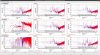
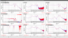
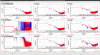
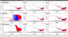
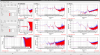
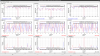
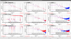
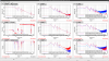
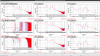
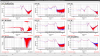
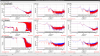
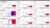
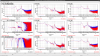
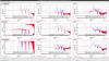
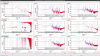
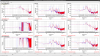
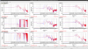
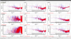
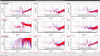
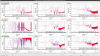
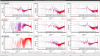
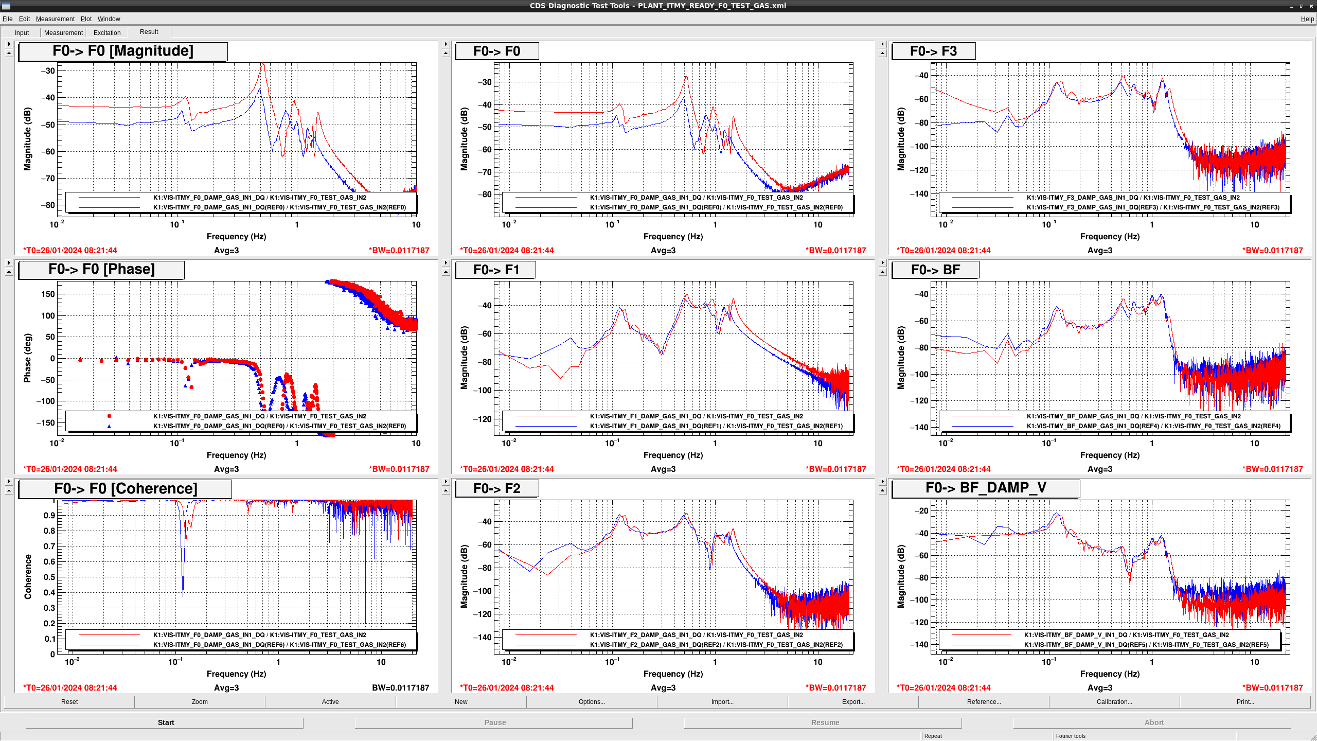
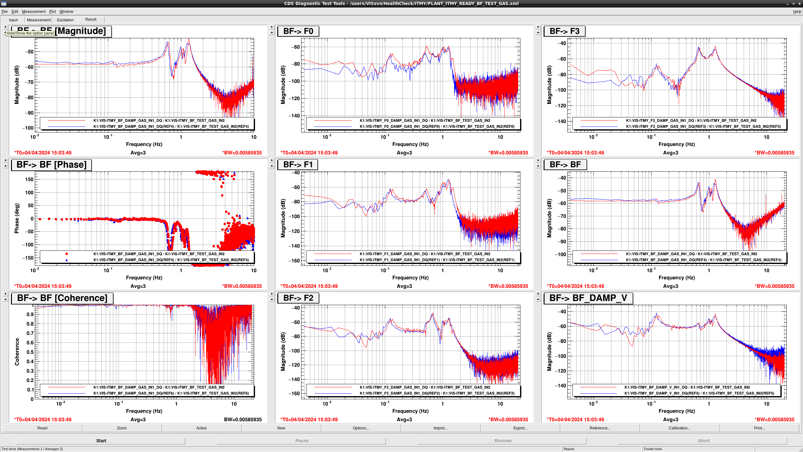
After the offload work by Takahashi-san (klog28431), I measured GAS filter TFs again.
Figure 1-5 show the result.
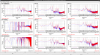
F0 GAS TF has a larger overall gain, which is probably because the F0 GAS LVDT position is close to the edge of the linear range according to the calibration measurement of F0 GAS LVDT (PDF).
F1 GAS TF has larger gain at high frequency but I have no idea why. it might be same reason as F0 GAS but no measured raw data of LVDT signals.
F2 GAS TF is recovered and seems healthy thanks to the offload work.
F3 and BF GAS TFs also seem healthy.
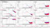
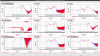
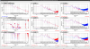
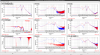
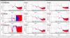
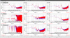
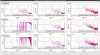
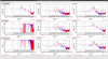
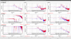
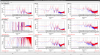
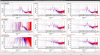
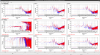
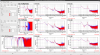
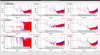
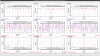
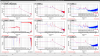
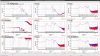
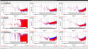
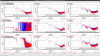
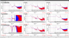
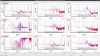
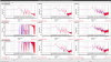
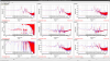
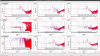
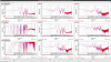
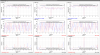
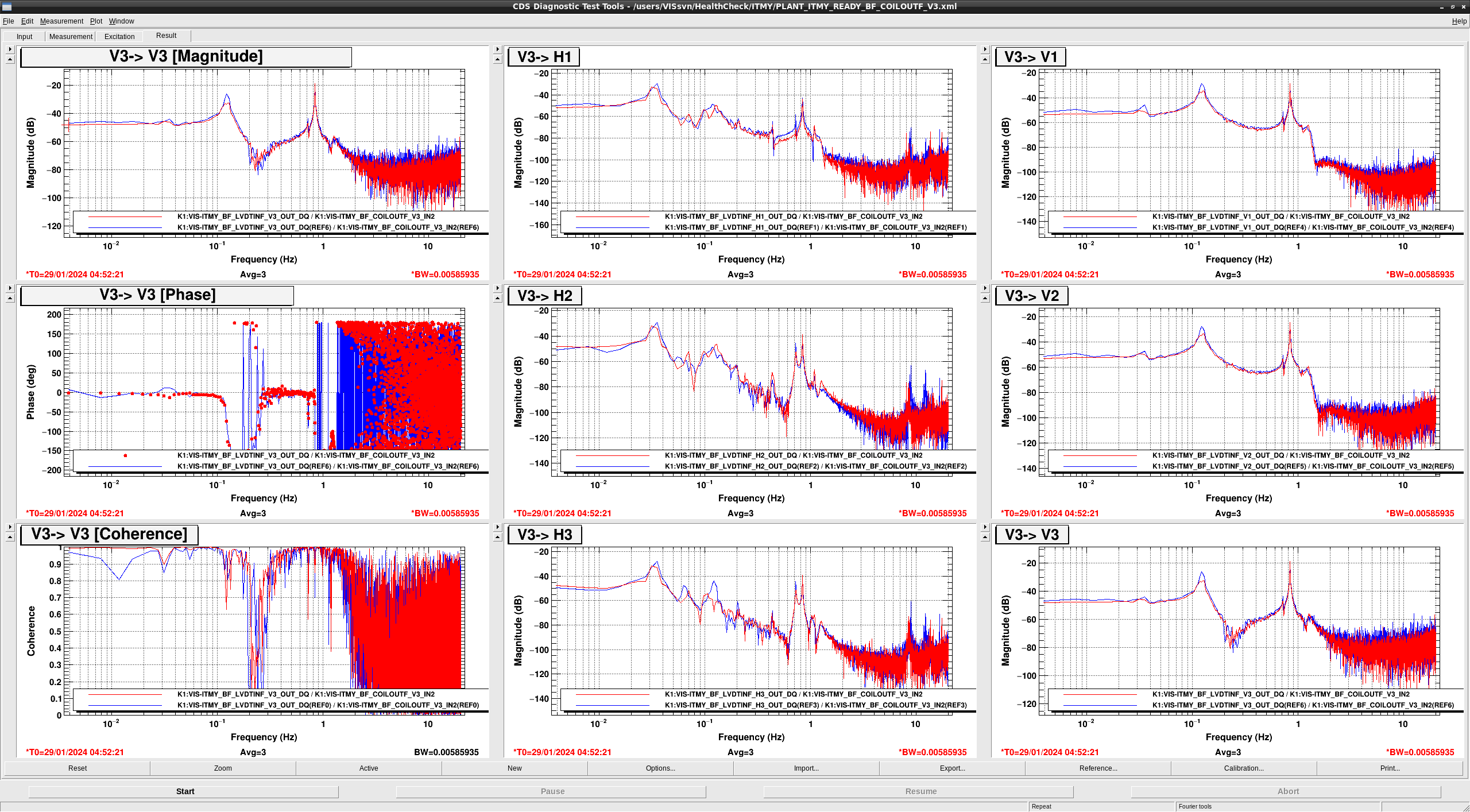
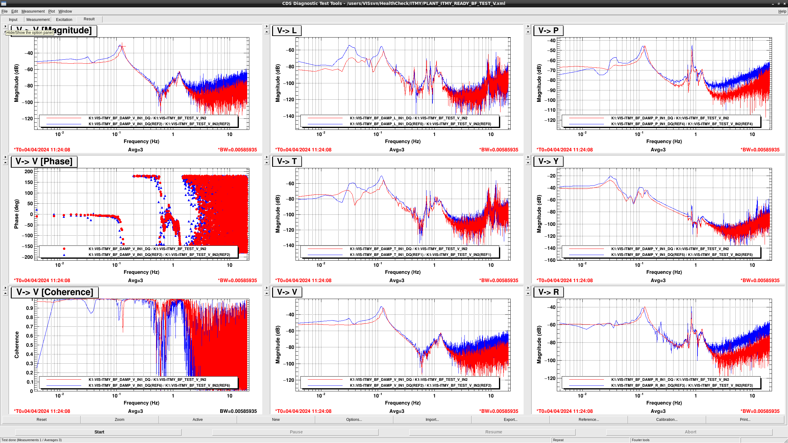
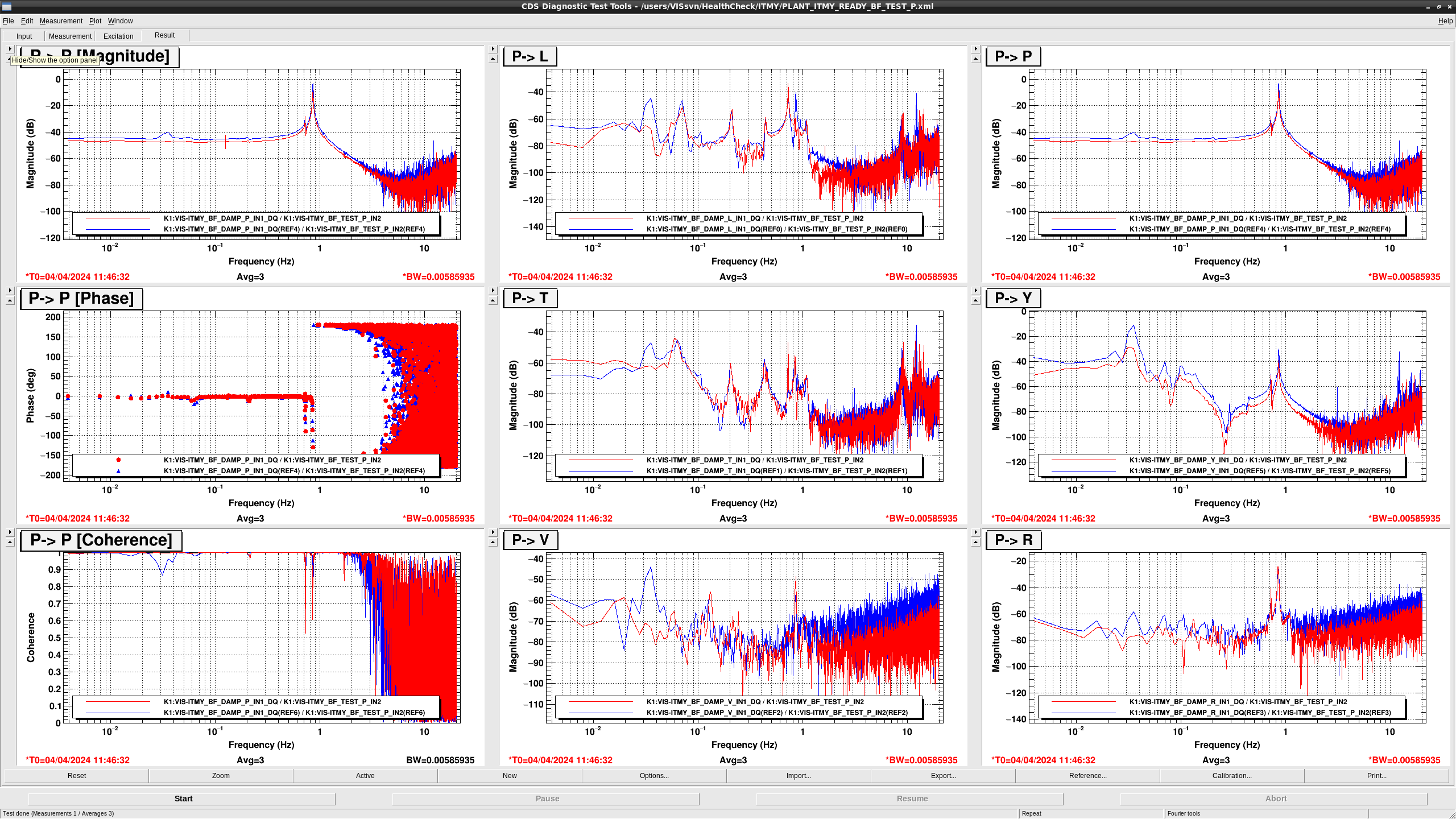
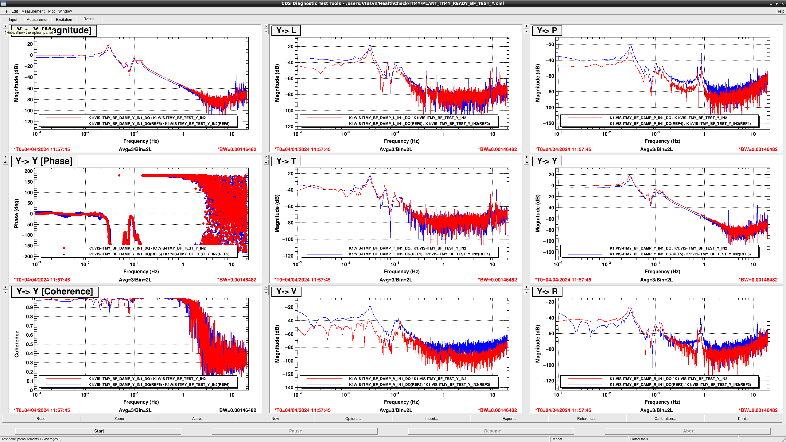
After Takahashi-san's offload, we performed the Health check again for the BF stage.
Originally, there are some peaks from 0.2 Hz to 0.5 Hz in vertical sensors and in DoF (V, P, R) sensors related vertical sensors. After the offload, their peaks disappeared and the TFs seem to got healthy.
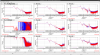
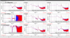
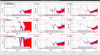
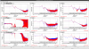

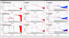
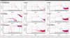
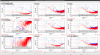
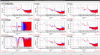
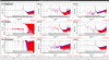
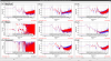
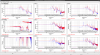
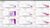
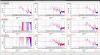
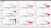
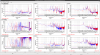
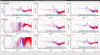
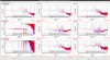
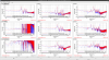
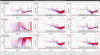
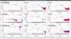
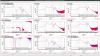
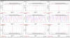
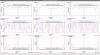
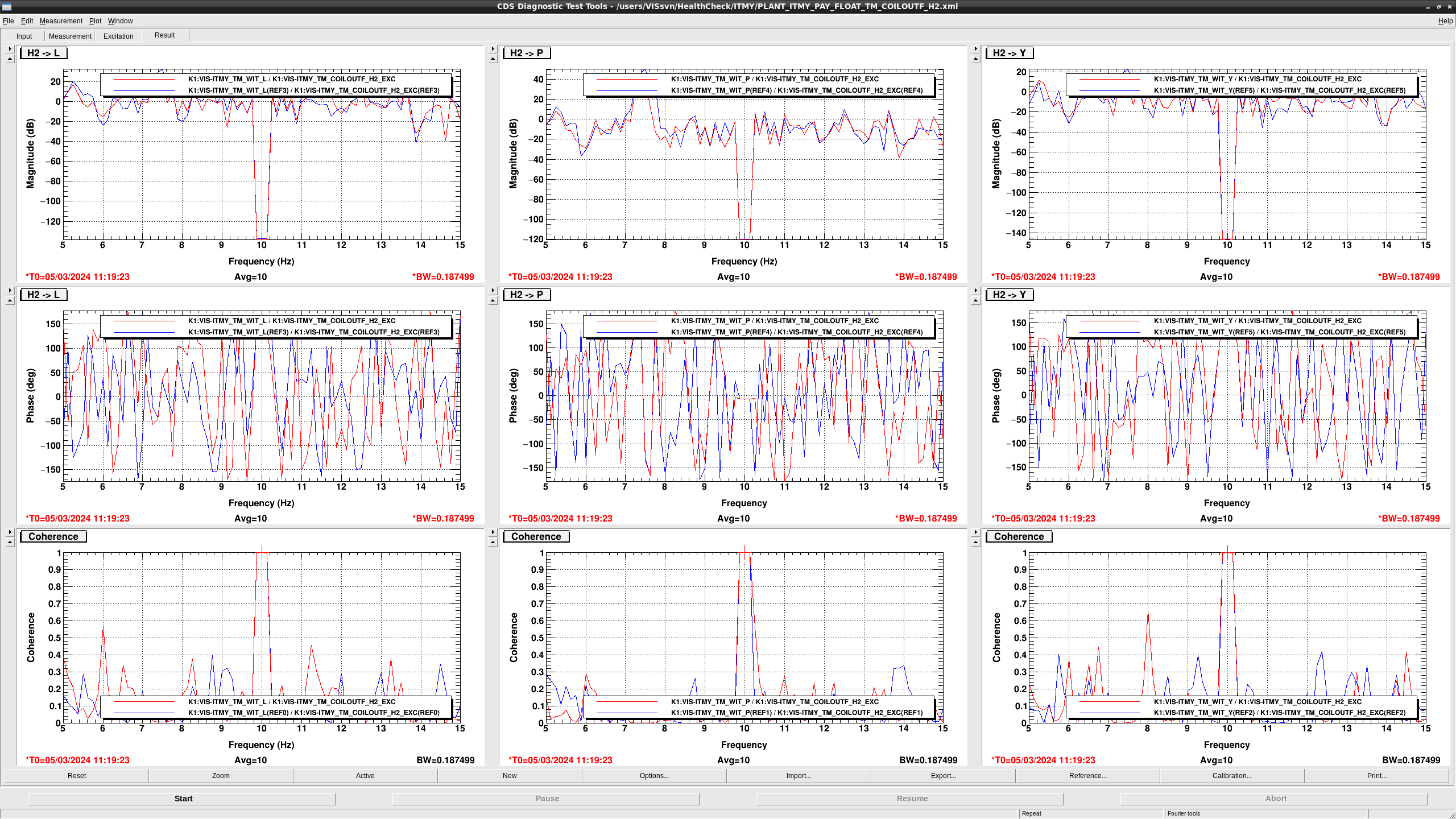
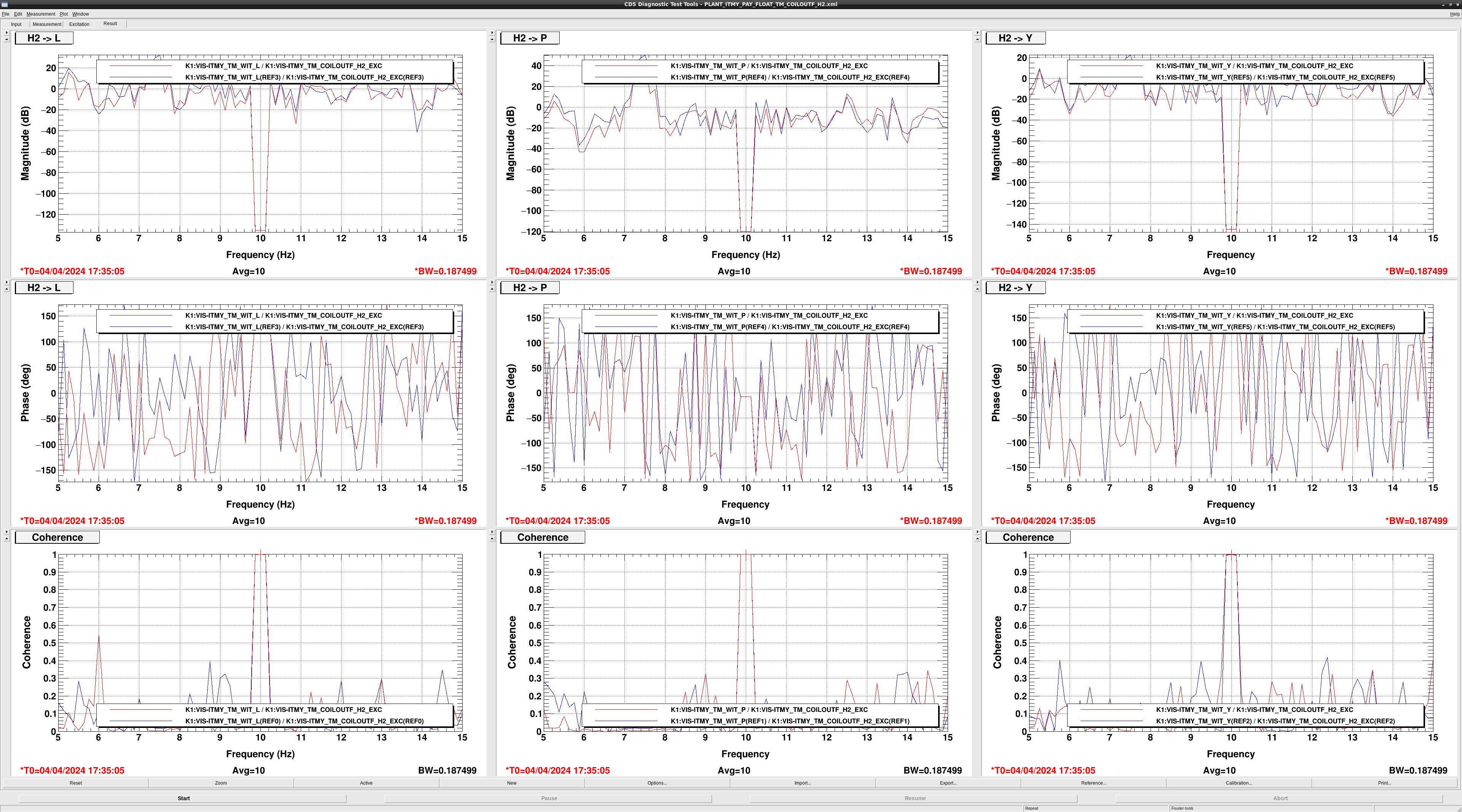
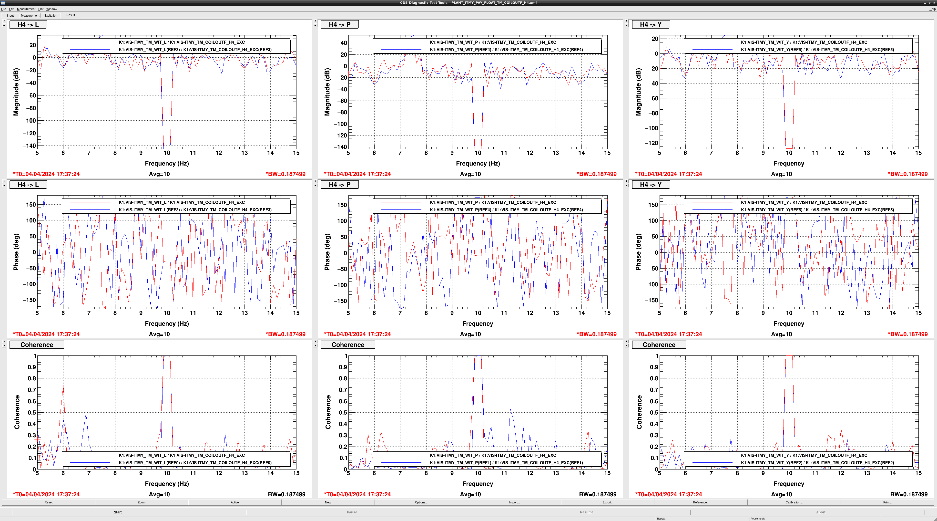
I checked ITMY TM actuators and confirmed all seem fine (fig1-4).

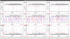
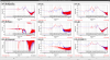
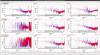
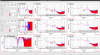
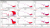
Attached figures show the TF measurement results of ITMY.
Some GAS TFs changed but there seems no serious problem.
GAS TFs are better to be checked by Takahashi-san.
Followings are some note:
1. IP_IDAMP_L and IP_IDAMP_T are now mixed signals of geophone and accelerometer while they were just geophone signals when reference TFs were measured.
2. I have no idea on gain increase of F0 and F1 at high frequency.
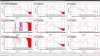

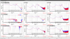

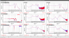
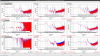

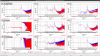

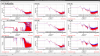
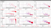
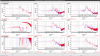
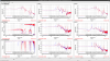

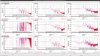
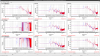
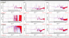
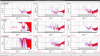

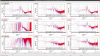
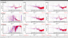
TM transfer functions.