Reports 1-1 of 1 Clear search Modify search
MIF (Noise Budget)
tomotada.akutsu - 16:46 Sunday 26 March 2023 (24537) Print this report
Projection of IMMT1T PIT onto DARM; revisited

Following 24187, 24529.

Summary

As already known, the spectral bumpy structure in DARM at around 117 Hz would be due to the angular jitter of the input beam. What is strange is that the corresponding bumps at IMMT1T seems only grown during PRFPMI locked, and not found when it is down. Considering the control topology, this should not happen. This post is to show the points by creating the attached figures.

Details

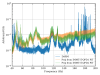
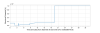
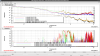
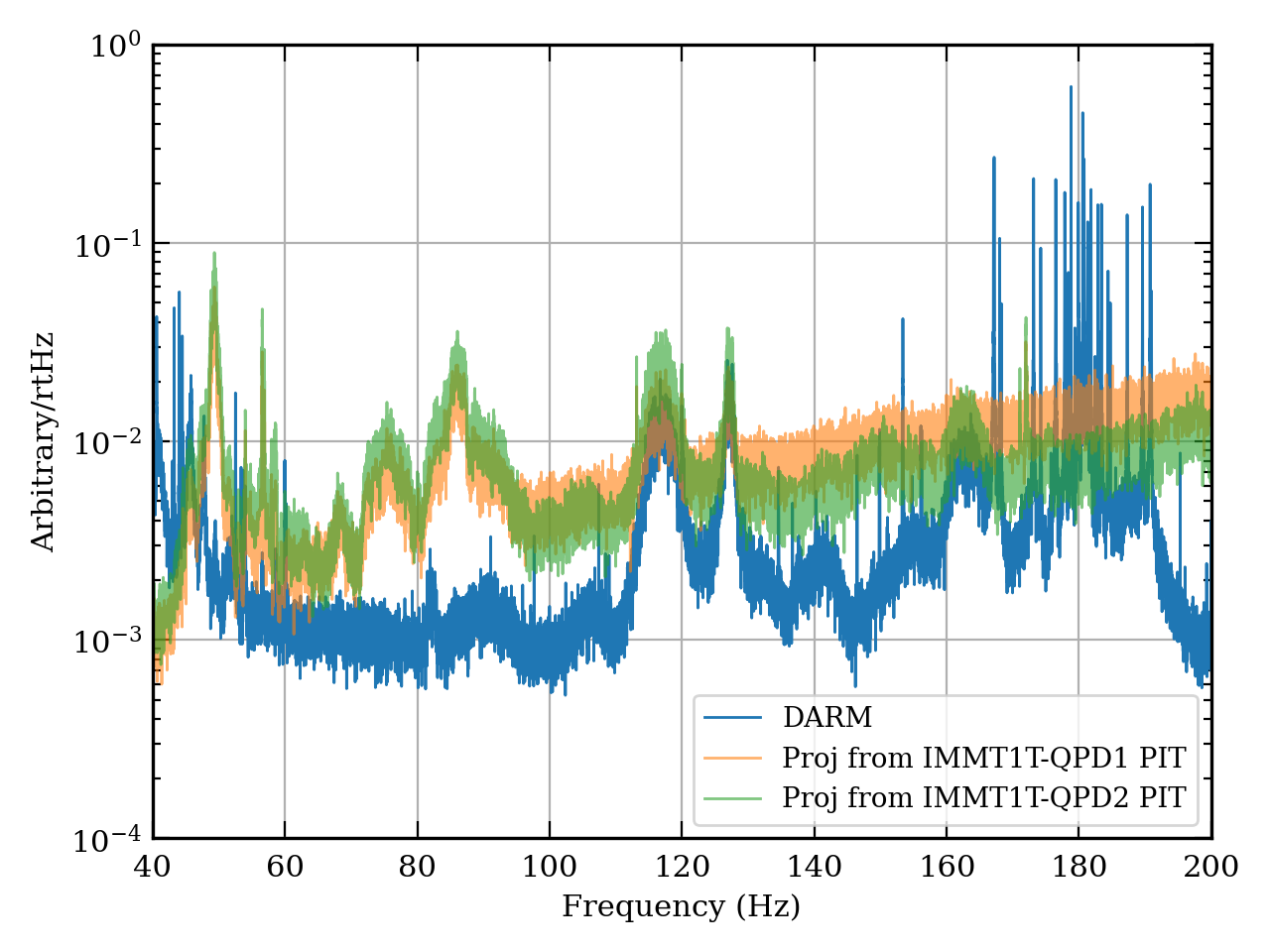
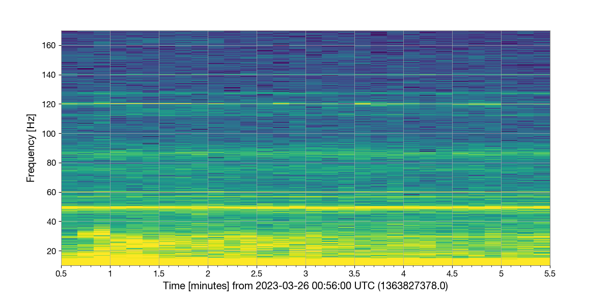
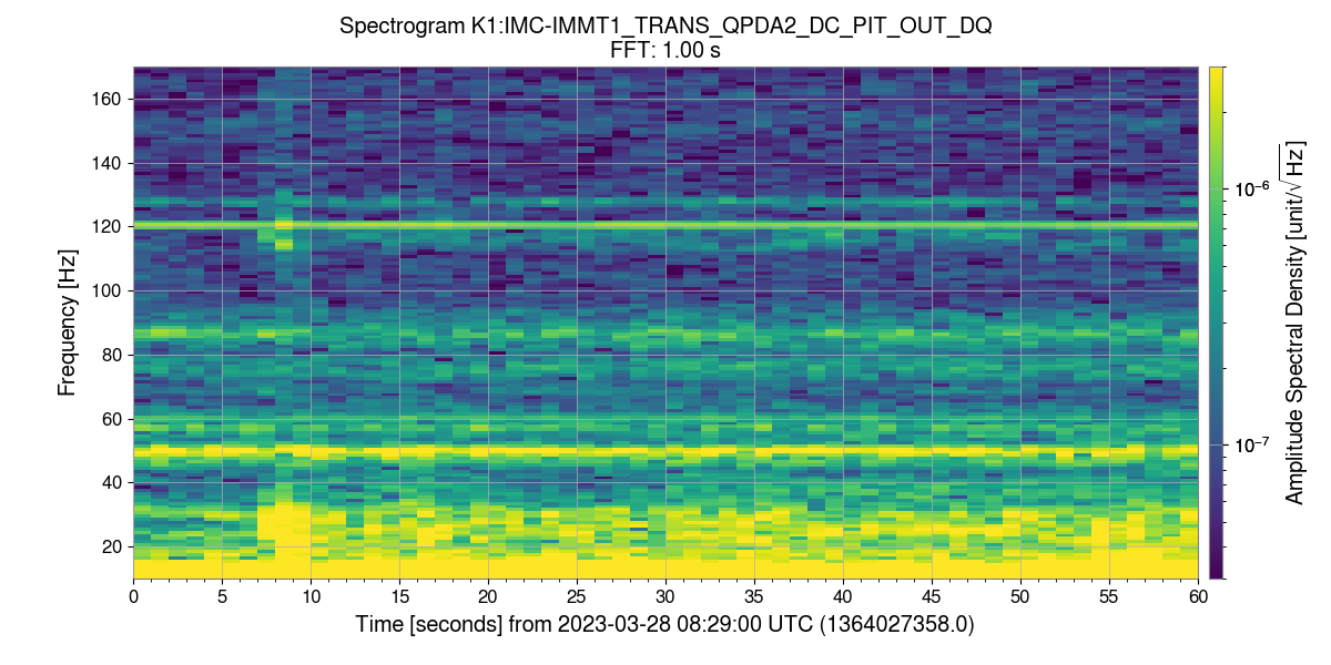
Fig. 1 shows projection from IMMT1T QPDs (K1:IMC-IMMT1_TRANS_QPDA{1,2}_DC_PIT_OUT_DQ) to DARM (K1:CAL-CS_PROC_DARM_DISPLACEMENT_DQ) made with the same transfer function (-4*x^2; in other words, I reused this same transfer function) introduced in 24187 in the silent run on Mar. 21 00:00:00 UTC (see 24475). In fact the S/N of the QPD output is better for QPD2 than that of QPD1, but the transfer function was of QPD1, so I plot both; these QPDs show slightly different gain seemingly. Anyway, It is obvious, at least the 117 Hz bumpy structure, the 128 Hz stable peak, and the 163 Hz bump would be related to the angular jitter of the input beam that can be detected with these IMMT1 transmission QPDs. This has been already known since 24187.

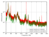
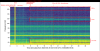
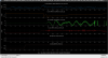
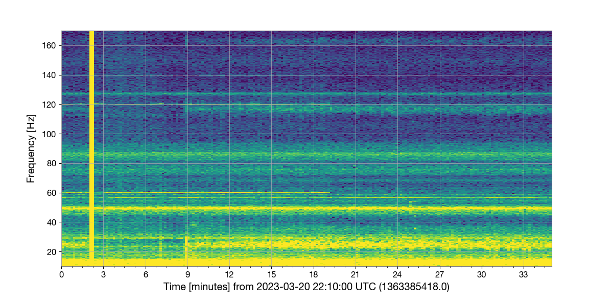
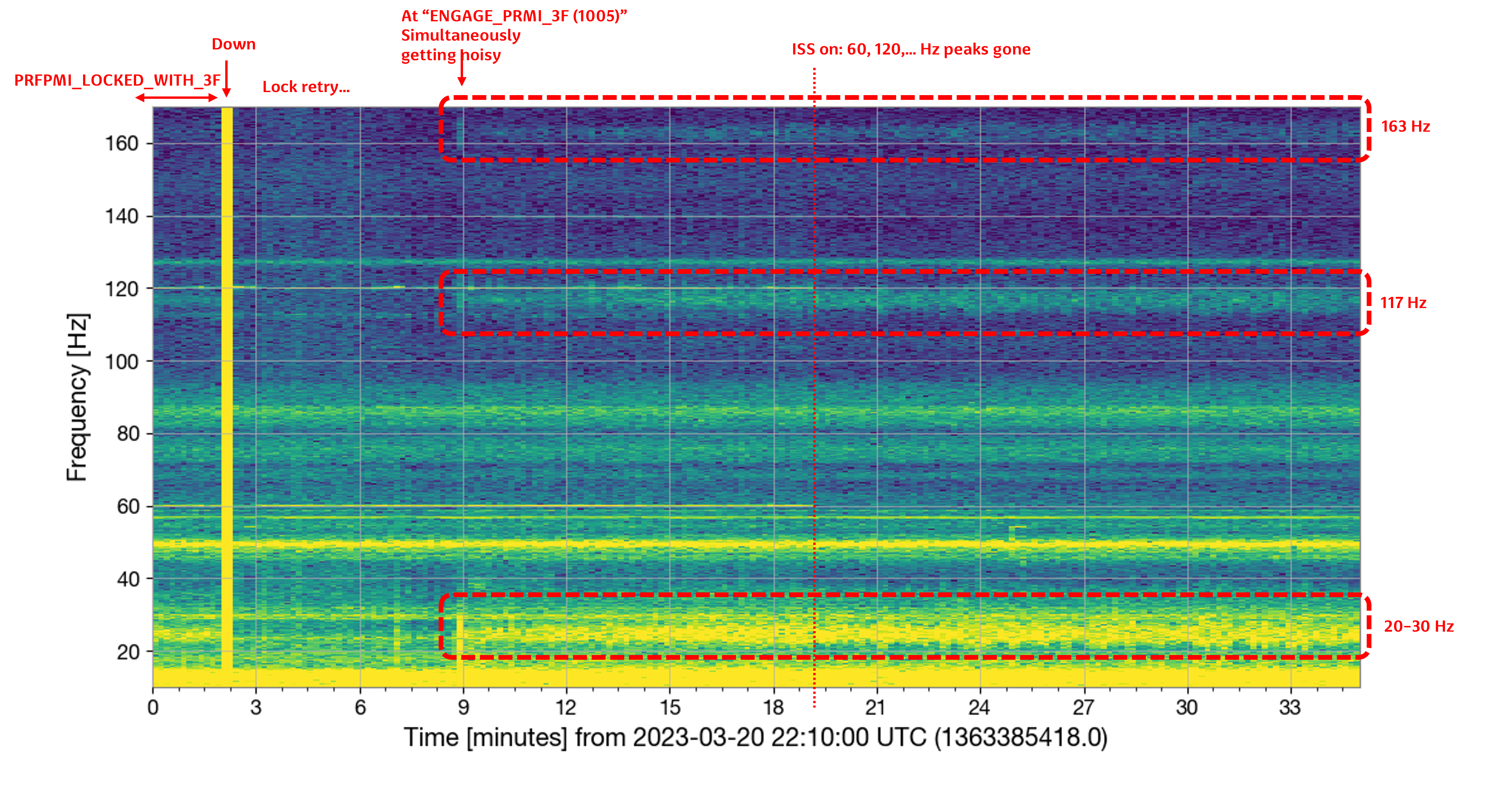
The strange thnig is related with the fact already reported in 24529. To repeat the point, Fig. 2 shows that the bumpy structures around 117 Hz and 163 Hz get larger when PRFPMI locked (or, during the silent run, of Mar. 21 00:00:00 UTC), while they are less when the interferometer is down (of Mar. 21 02:00:00 UTC) but IO Gurdian is in PROVIDING_STABLE_LIGHT. So, the question is why these bumpy structures appear in IMMT1T QPDs when the interferometer locked? Understanding the mechanism how the bumps appear in the QPDs will make DARM better, I guess.

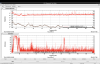
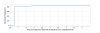
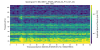
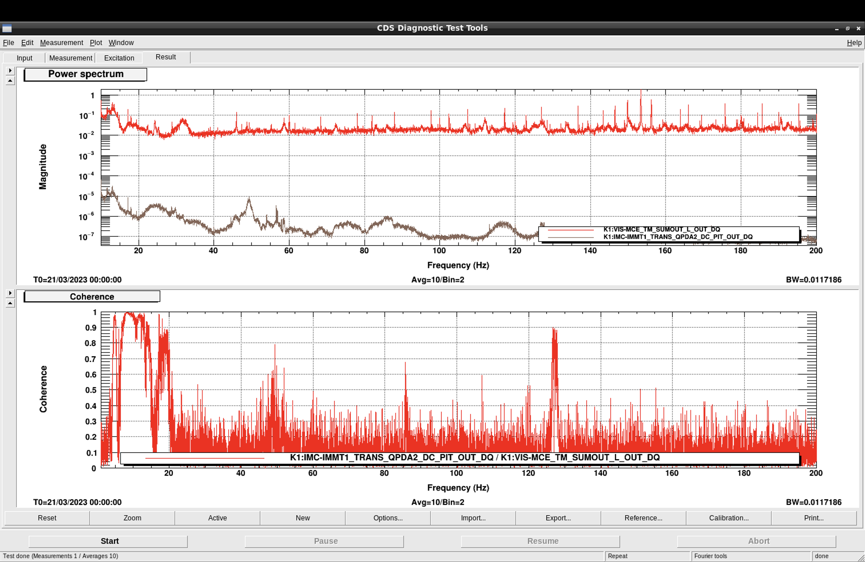
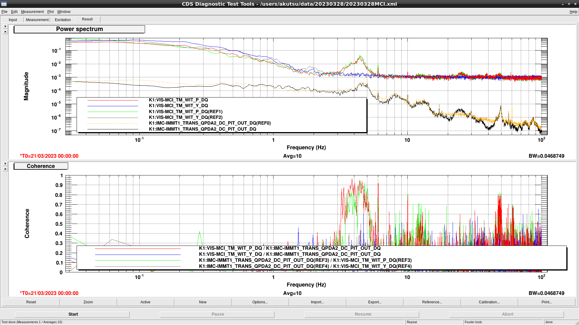
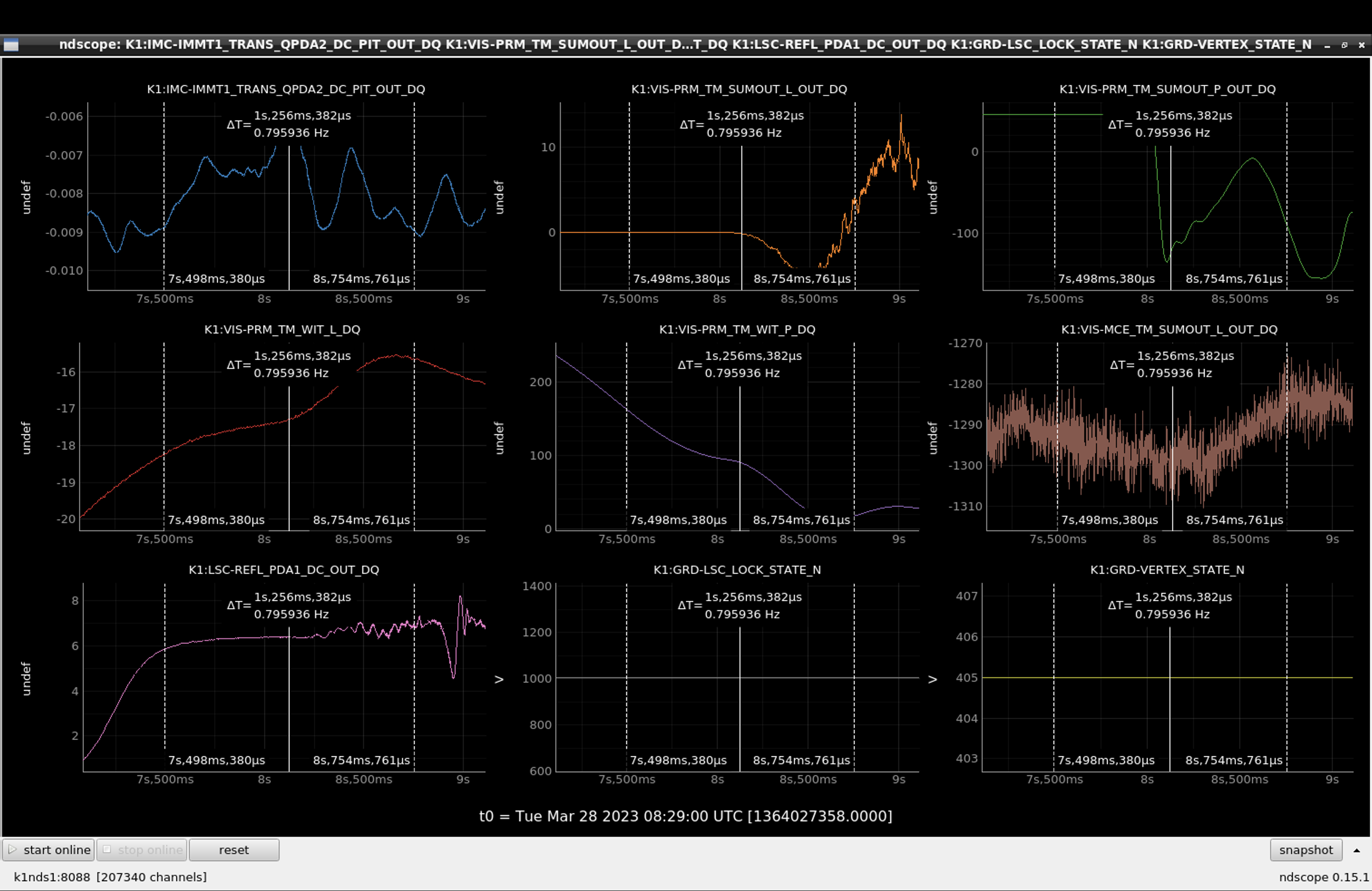
The first scenario might be due to some coupling from MCL feedaround during PRFPMI locked. Fig. 3 shows the relevant signals, but there are no coherence with the 117 Hz bump in IMMT1T QPD and MCE input signal, while there is strong coherence around 127 Hz, which is we know a stable peak found in DARM, IMMT1T, and CARM-related signals (but may be not so related to the current issue, although we love to damp it...). Then, whar is the next candidate of the scenario...???

Anyway, the other things I noticed in Fig. 3 are

  • Why the 60 Hz power line (maybe) and its hramonics are only seen when down?
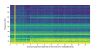
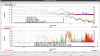
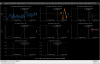
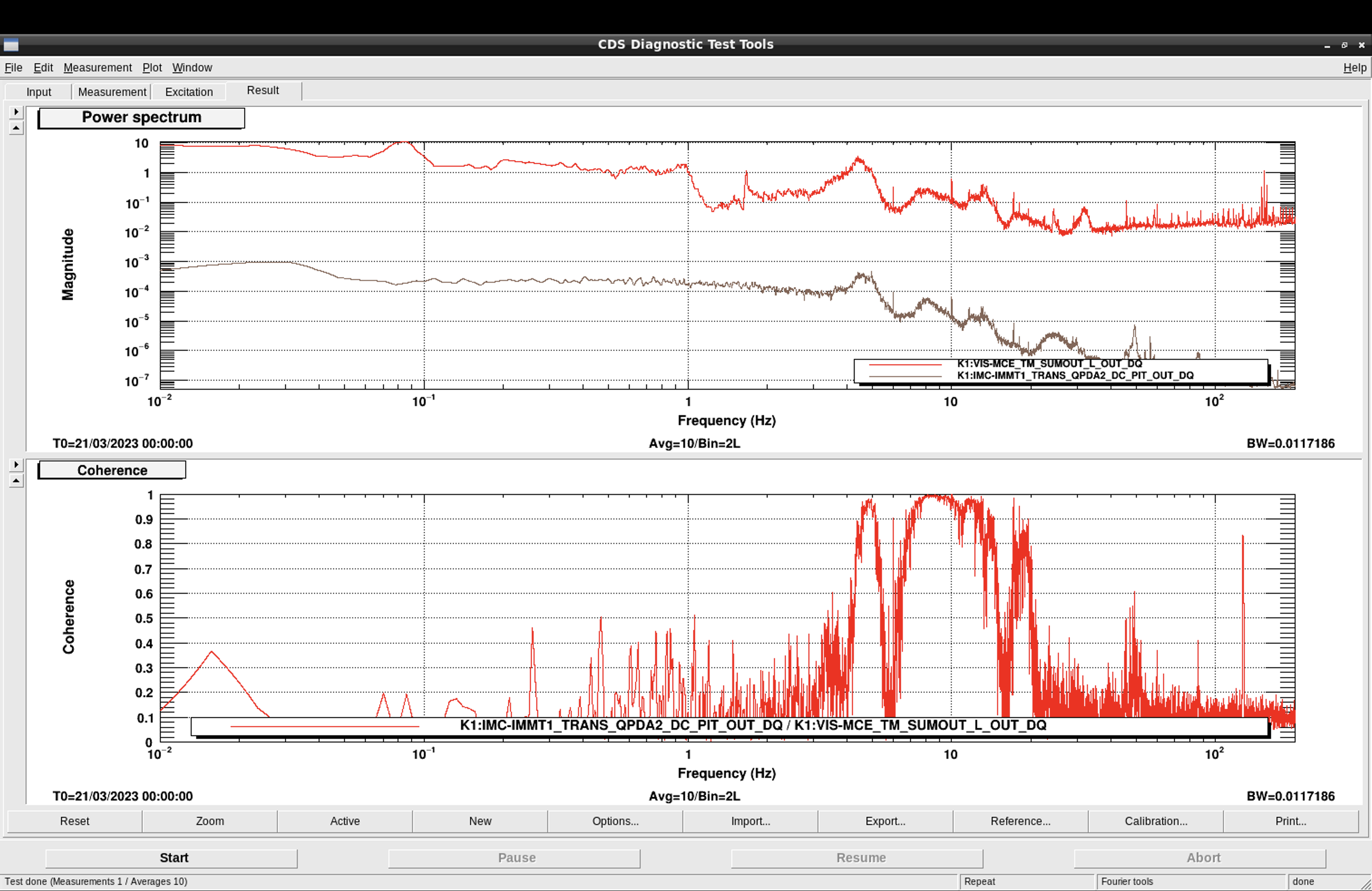
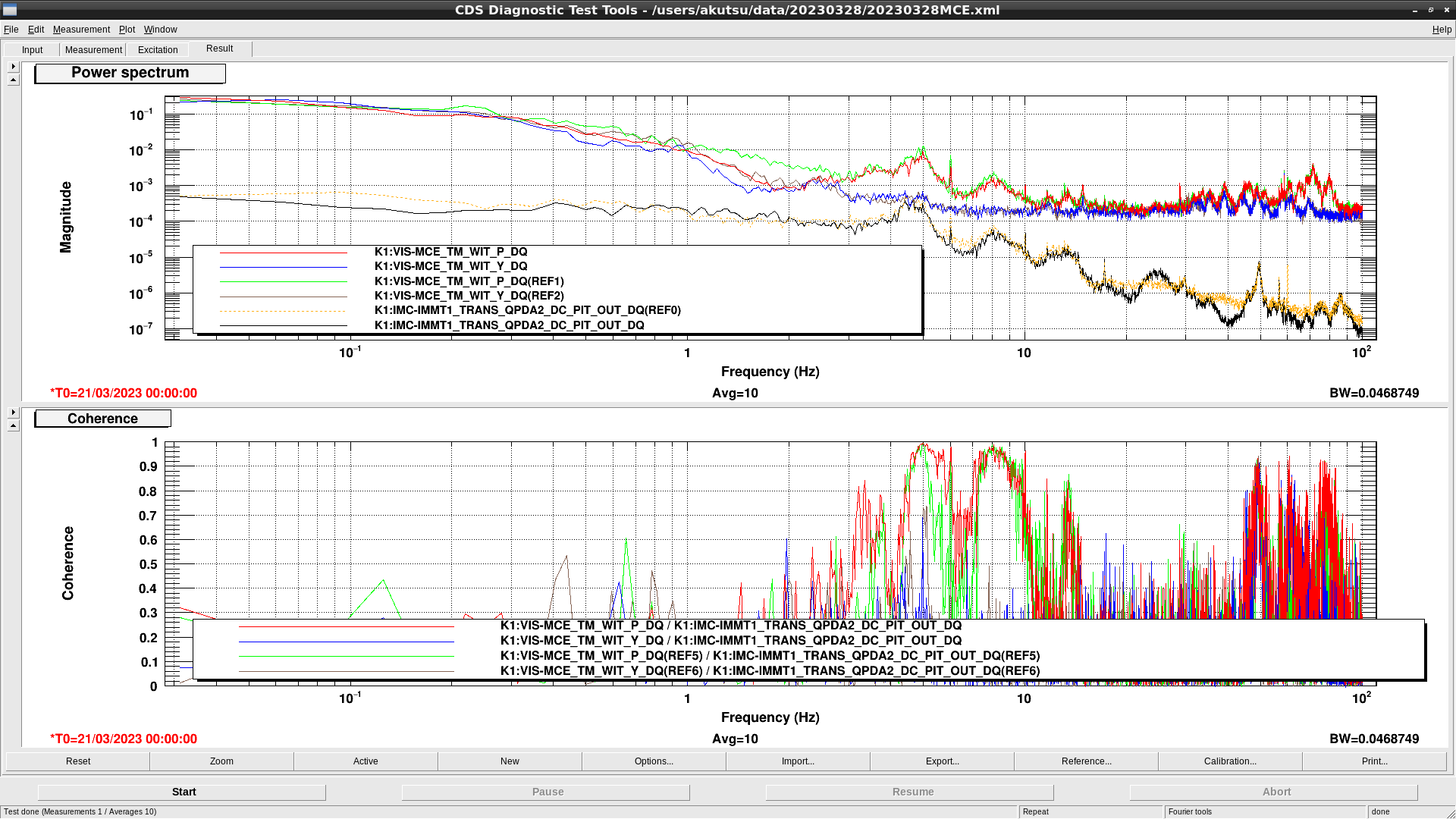
  • Strong coherence below 20 Hz. Do we need more diagonalization of P/L for the MCE suspension? Is there possibility that this unwanted pitch input may have upconversion to 117 Hz? Indeed there are several other bumps found in IMMT1T when PRFPMI locked. For reference Fig. 4 is wider version of Fig. 3. Do we already have a measured transfer function from MCL excitation to DARM?

By the way the other peaks in IMMT1T that are not correlated with DARM seems to be due to the fluctuation of the pylon; they have strong coherence with IMMT1T oplev signals at these peaks.

Images attached to this report
Comments to this report:
tomotada.akutsu - 18:10 Sunday 26 March 2023 (24538) Print this report

The reduction of the 60 Hz power-line-like peak and its harmonics might be due/thaks to ISS on, though we need to check when they disappear step by step to confirm this theory definitely. Anyway, checking each state of Guardian would be worth doing for the other questions.

tomotada.akutsu - 18:10 Monday 27 March 2023 (24557) Print this report

Further investigation to study in which state the IMMT1 trans QPDs gets noisy. Fig. 1 is the spectrogram of K1:IMC-IMMT1_TRANS_QPDA2_DC_PIT_OUT_DQ, and Fig. 2 is K1:GRD-LSC_LOCK_STATE_N.

Fig. 3 shows some analysis of the behavior.

  • The 20-30 Hz, 117 Hz, and 163 Hz bumps excite when the guardian state is ENGAGE_PRMI_3F.
  • The 60 Hz, 120Hz, ... power-line-like peaks disapper after ISS.
Images attached to this comment
tomotada.akutsu - 22:03 Monday 27 March 2023 (24560) Print this report

Ushiba, Akutsu

In 24557, it is hard to bring reasonable theories why PRMI 3F lock would cause beam jitter. To break down this difficult problem, we checked if the same behavior would be observered even in the PRMI with ETMs misaligned (simply putting, no arms), or in other words, during the initial alignment.

Fig. 1 is the spectrogram of K1:IMC-IMMT1_TRANS_QPDA2_DC_PIT_OUT_DQ, while Fig. 2 is a time series of K1:GRD-INITIAL_ALIGNMENT_STATE_N. Taken from Mar 26 2023 00:56:30 UTC to Mar 26 2023 01:01:30 UTC. As shown in these figures, although the Guardian state evolved, IMMT1 trans QPD did not show any significant changes in the spectrogram.

So what do these facts (this post and 24557) mean? What is the path of the noise? How arm signals affect this? And what is the actuator of this beam jitter even in 100 Hz?

Images attached to this comment
tomotada.akutsu - 22:29 Tuesday 28 March 2023 (24576) Print this report

Not much successful information.

Regarding the IMMT1 trans QPD signals, if the bumps at 20-30 Hz, 117 Hz, and 163 Hz... would be really the angular jitter of the input beam, it would be natural to assume that such jitter must happened due to whichever IMC mirrors. I hoped that 20-30 Hz bump could be seen with relevant oplevs somehow, but in fact no such features. Some oplevs would need more S/N. Anyway, the 117 Hz bump, if any, would have been under the noise floor.
In Fig. 1, 2 and 3,

  • Red, blue, and black curves are of March 21 00:00:00 UTC, during the silent run.
  • Green, brown, and yellow curves are of March 26 00:58:00 UTC, during PRMI for the intial alignment by operators (Why these timings? -> see 24560.

As a side product, some stable bump features in the IMMT1 trans QPDs at low frequency are somehow understood due to some of IMC mirrors, according to the coherence.

  • IMMT1 trans 3-5 Hz -> MCI
  • IMMT1 trans 6-8 Hz and 9-10 Hz -> MCO
  • IMMT1 trans 4-6 Hz and 7-10Hz -> MCE

To understand the situation more deeply, we may need to know UGFs of the IMC ASC control.

Interestingly, some features around 50-100Hz of IMMT1 trans QPD seems to have not low coherence with MCE, but at the same time these features can be also explained as the IMMT1 oplev pylon's resonance, according to the IMMT1 oplev signals. I'm not sure well why these have coherence with MCE pitch.

Images attached to this comment
tomotada.akutsu - 23:13 Tuesday 28 March 2023 (24577) Print this report

Following 24560 and 24557.

To look into the detail when the IMMT1 trans bumps would start, I compared a time series of some channels during lock aquitision today. Fig. 1 is the time series of relevant channels, while Fig. 2 is the IMMT1 trans QPD's spectrogram (1 sec resolution). The time 0 is the same instance for usability. It seems the timing around 7-8 sec would be the starting time of the bumpy at 20-30Hz; in this spectrogram, the 117 Hz bump would not be clearly seen, but in spectra at the corresponding time, it can be seen (need 1 Hz resolution with 3 avg, for example). Anyway, looking at the corresponding time in Fig. 1, the shook timing would be seen in IMMT1 trans signal (the first blue curve), and  maybe the following two would be the relevant clues:

  • PRM pitch suddenly responded to something at 8 sec.
  • REFL RF PD' DC suddenly responded to something at 7.5 sec.

Maybe there might be another hidden state changes... For wider time window, see Fig. 3. At around 30 sec, ADS dithering of PRM started (not shown here, but dithering BS and IMMT2 also started simultaneously).

Anyway, totally no idea I have. Need more accumulation of facts.

Images attached to this comment
tomotada.akutsu - 8:30 Wednesday 29 March 2023 (24582) Print this report

Addditive information. I added PRM oplev channel to the figure of 24577, and expanded the timing of the transition. It seems, when the PRM alignment (known with the oplev) come close to zero, or come beyond a certain threshold, the transition would happen. This is just a phenomenological description, and so we need further stduy.

If taking better alignment of PRMI brings worse sensitivity, that would be a sad.

Images attached to this comment
tomotada.akutsu - 11:56 Wednesday 29 March 2023 (24588) Print this report

Added MCL in the figure of 24582. This time, the time cursor in Fig. 1 is put at the inflection point of the MCL time series (brown curve), which is very close to the transition timing of IMMT1 trans (blue curve). Fig. 2 is an expansion of Fig. 1. Note that before the time window we are looking at in these figures, MCL feed around due to ALS CARM had already started. For some reason, bringing PRM to the nominal position for PRFPMI made a kind of shock in MCL.

By the way, I would like ask some experts; can the situation shown in Fig. 3 happen? As we do not have MCE length sensor, it might be hard to check the local length behavior of MCE whether there would be any transitional variation of the behaior or not. The weak point of this theory is that it moves in horizontal or yaw in this figure ^^

Anyway, we need more statistics whether arm control existence would really affect the IMMT1 trans behavior or not; similar data as 24560 would need more.

Images attached to this comment
Search Help
×

Warning

×