Reports 1-1 of 1 Clear search Modify search
VAC (General)
shinji.miyoki - 9:00 Thursday 02 March 2023 (24226) Print this report
OMC pump unit support position

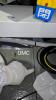
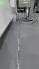
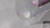
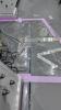
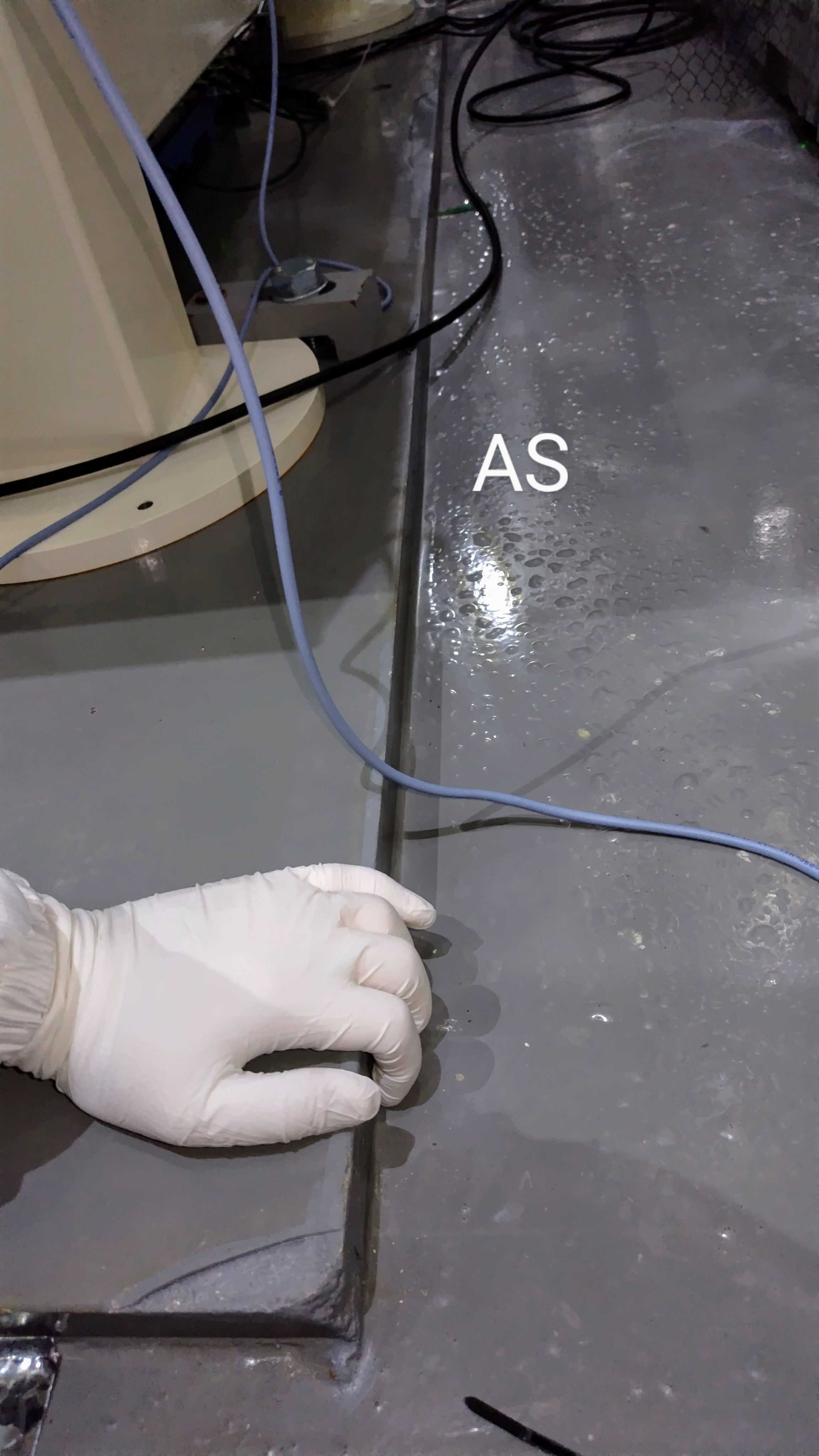
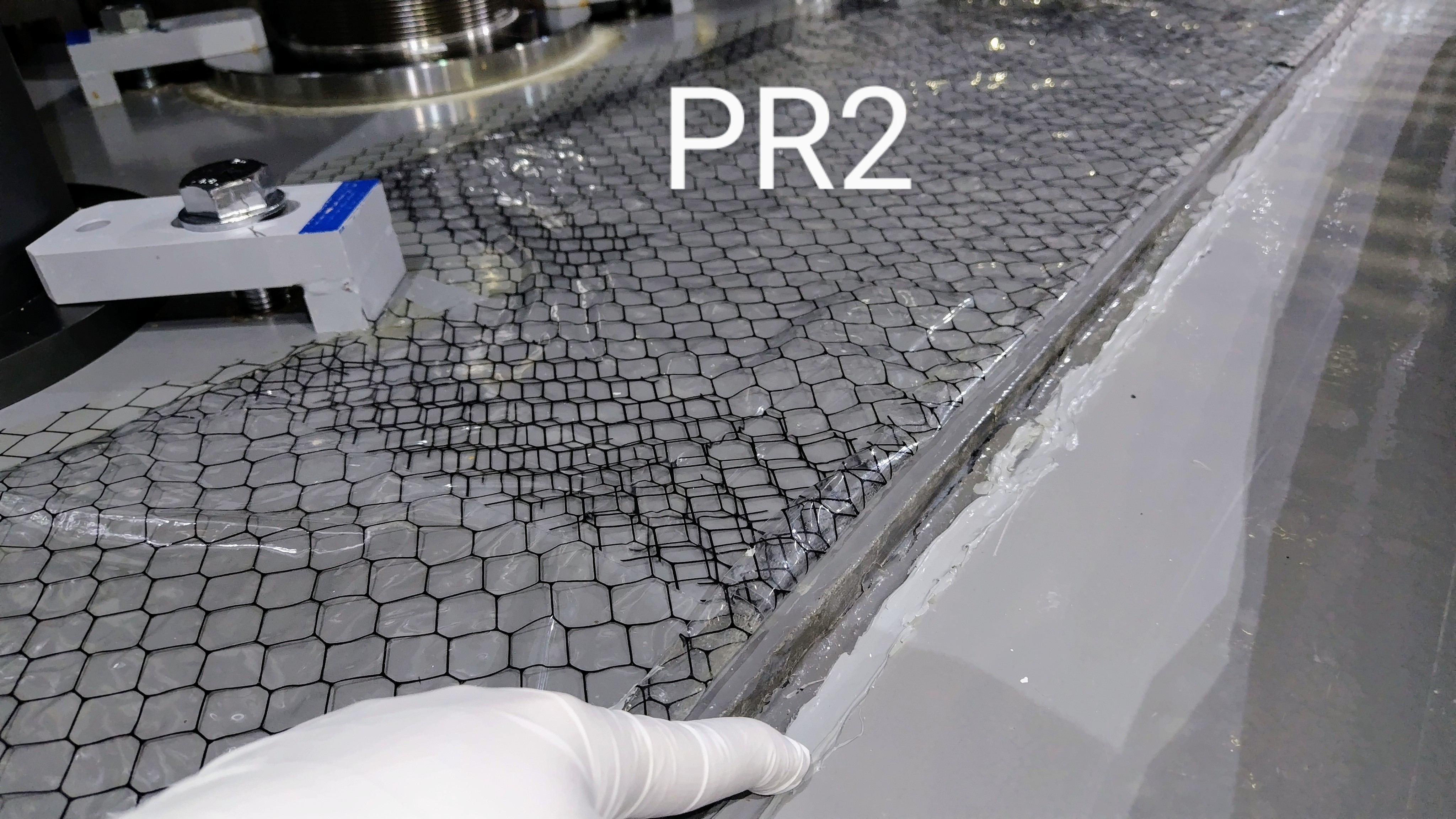
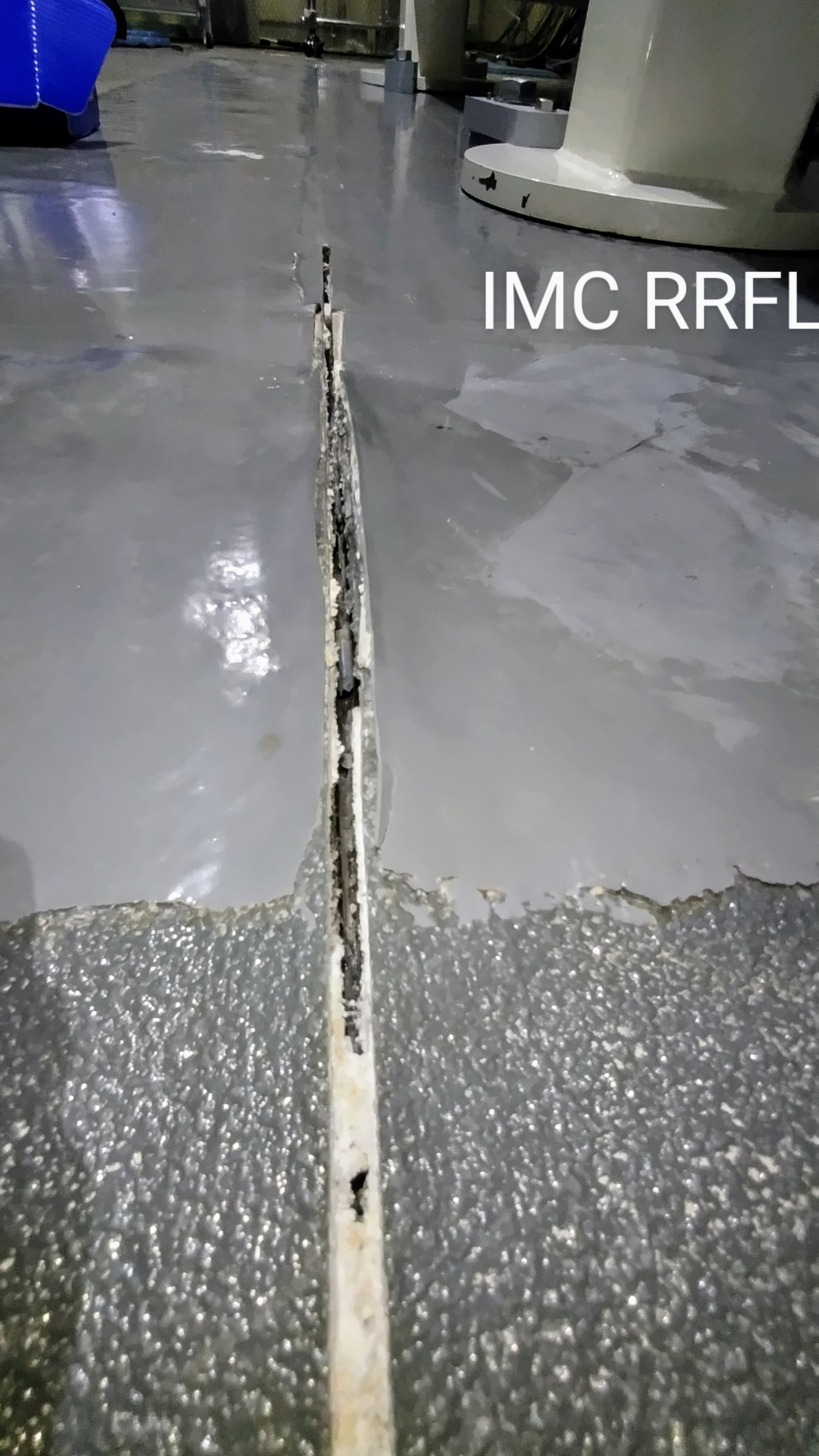
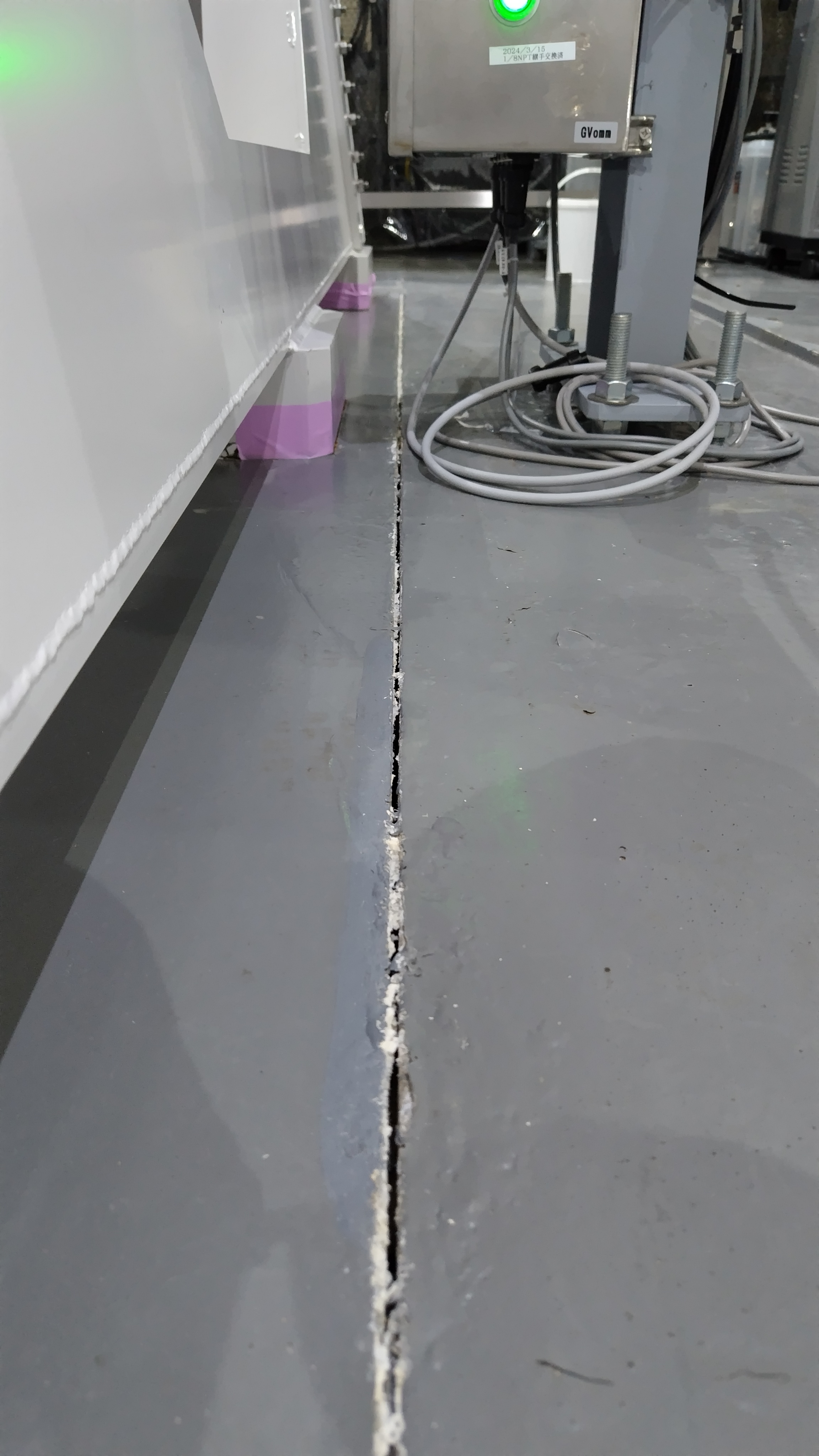
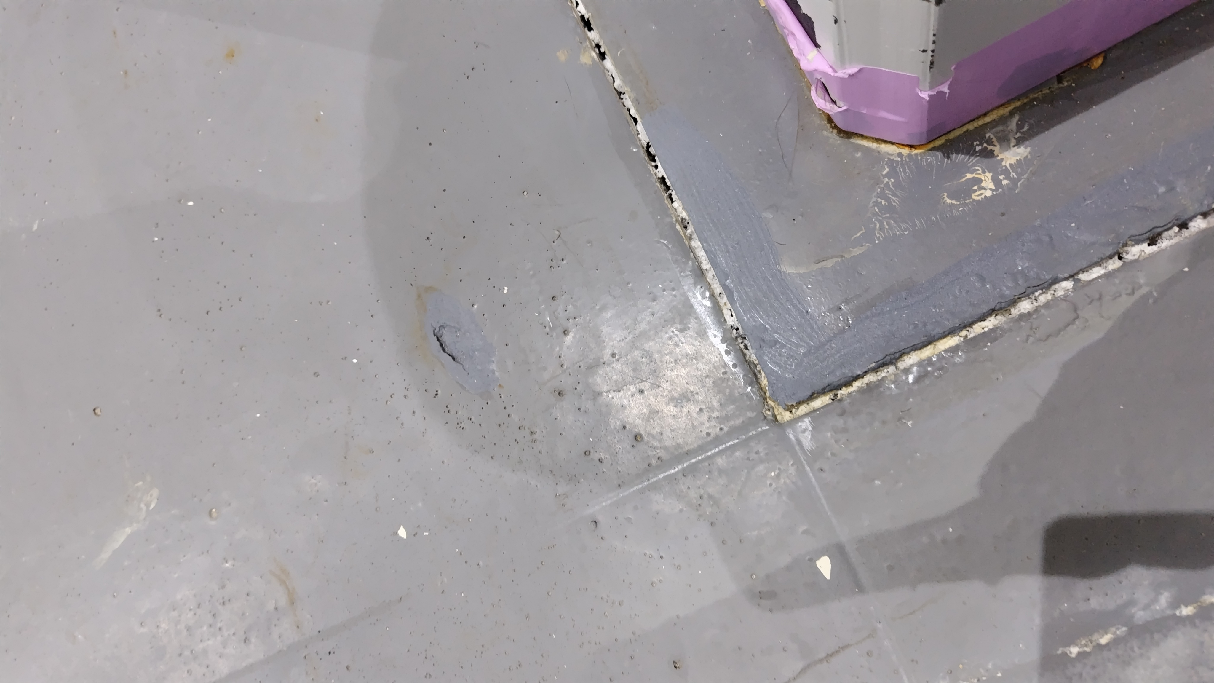
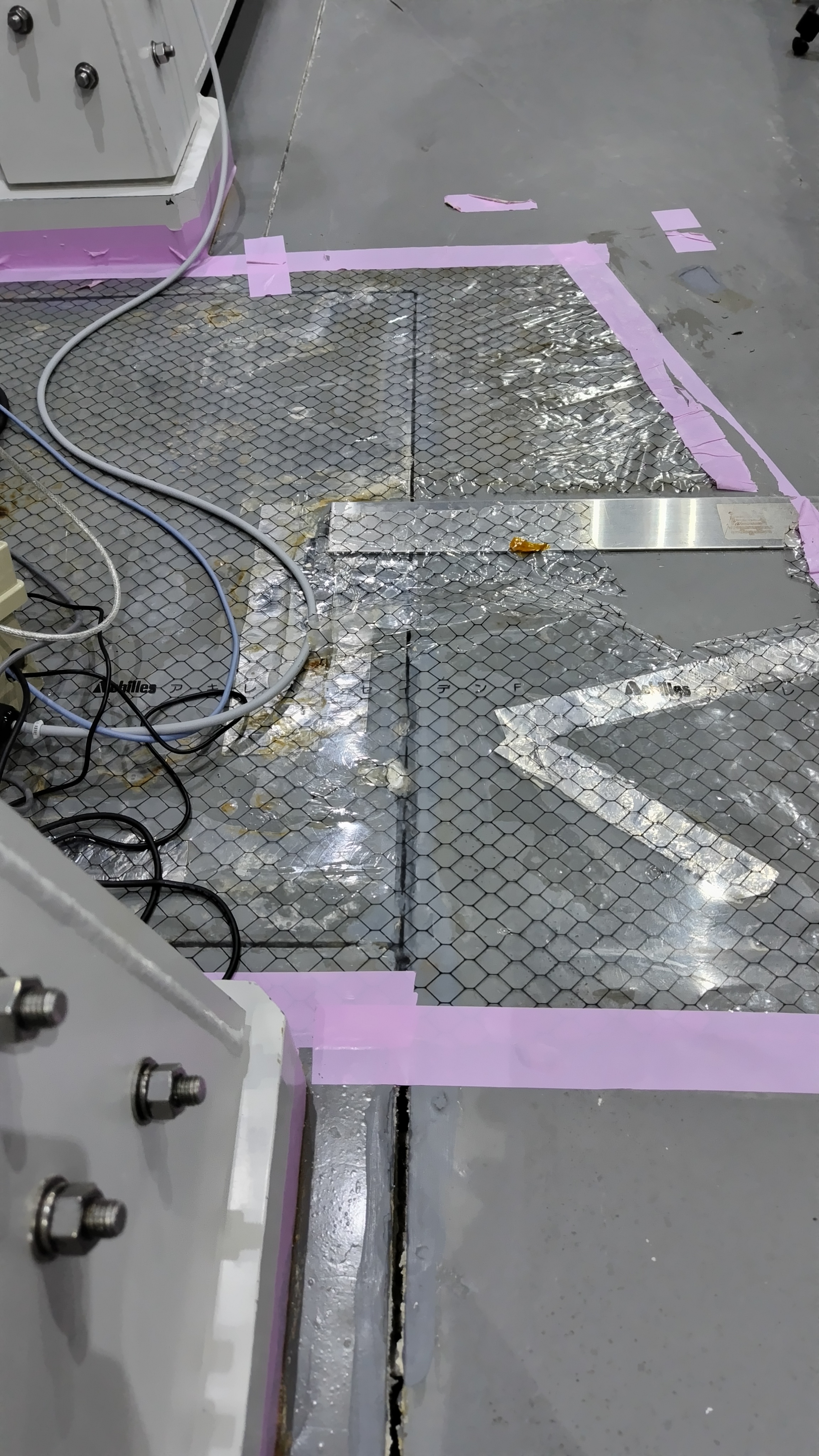
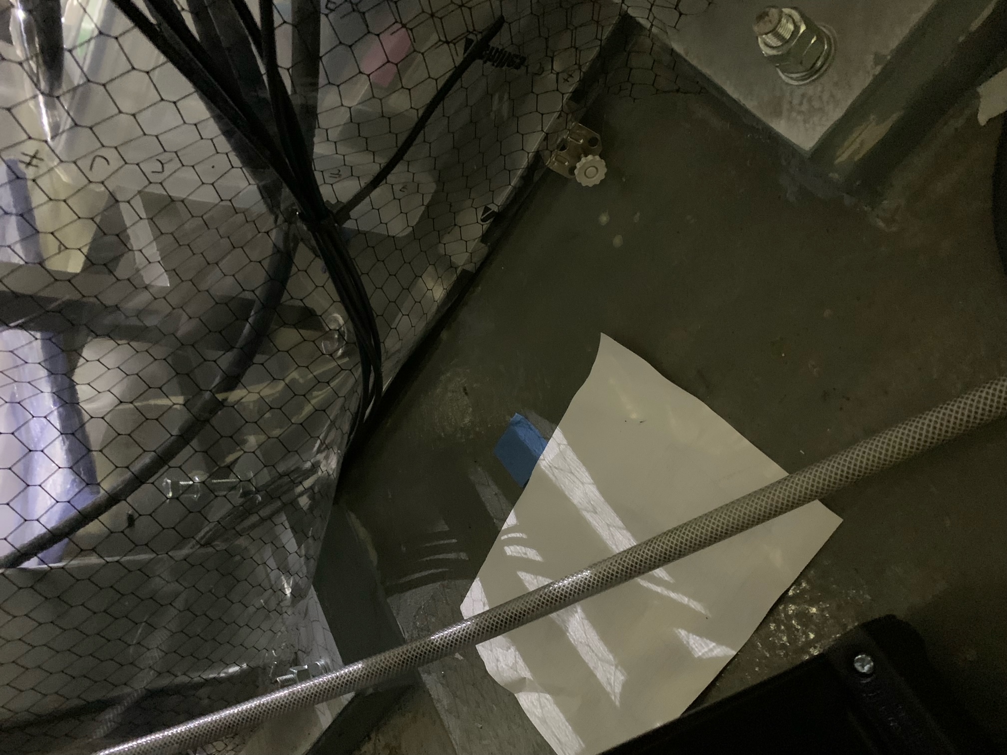
According to Saito-sensei, the cutting slits around the OMC and OMMT tanks were made and their surfaces were covered with soft material to avoid spring water. After that, the painting was done. So the slit surface maybe not be visible. The cutting slit area is the mortar area that is a little bit higher than the surrounding area.

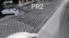
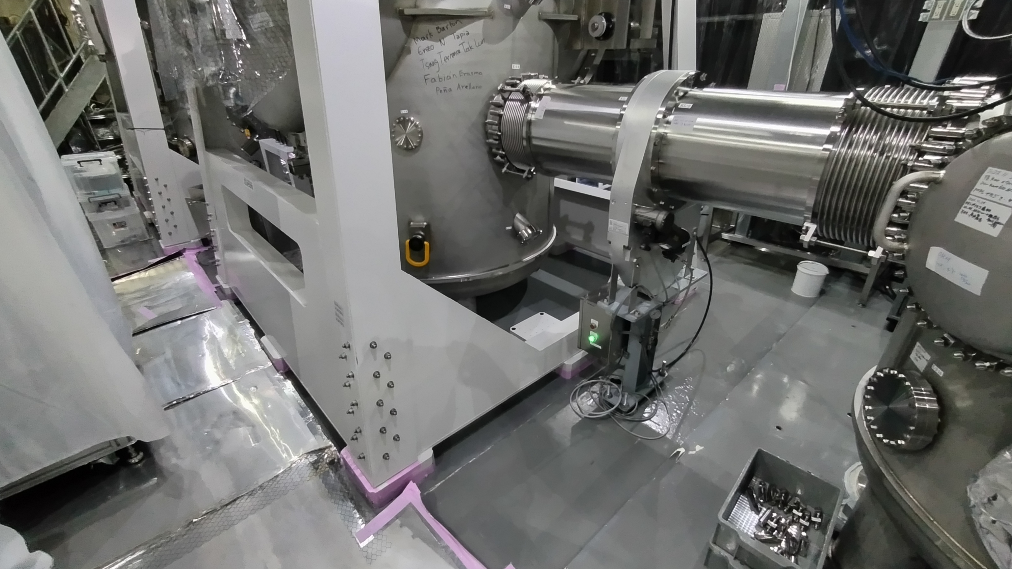
We are now discussing the present support rods for the pump unit should be released from the surface in the inside area of the slit cuttings. However, don't you think the present support is rather desirable, assuming no vibration from the Ion pump because all stuff of OMC-OMMT-TMP/Ion-Duct can be put inside the cutting slit area?  If we put TMP/IO unit on the outside area of the cutting slit, this structure can be the path of vibration from outside to OMC/OMMT.

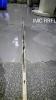
In this sense, the removal of KF40 bellows is important, and actually it was removed.

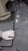
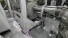
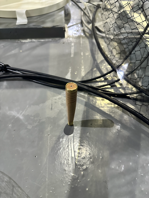
Strictly speaking, the Ion pump body is now supported by one? rod that is put on the cutting-slit-outer area because it's weight is so heavy. This is the only one path to introduce the vibration from outside to inside, except for the GV side and some cablings. So is it better to change this rigid support with a labo-jack-like lifter with a rubber? If this support rod is also in the inside area, it is no problem.

Comments to this report:
shinji.miyoki - 11:24 Thursday 02 March 2023 (24228) Print this report

I confirmed that the cutting slits do exist around the OMC and OMMT as the attached design.

All four support legs of TMP/ION white frame unit are set on the mortar area, that is inside the cutting slit area.

TMP and Ion are supported by additional legs on the white frame unit. So we need not worry about the additional vibration path through Ion pump support.

Non-image files attached to this comment
tatsuki.washimi - 16:21 Wednesday 10 April 2024 (29170) Print this report

I investigated whether trench cutting exists or not.
Around OMC and AS, I pushed the edge of the mortar concrete (the drawing shows there is trench cutting), but it was hard. I think there are no trenches.

For comparison, I saw around the PR2. I found a rubber line just outside of the mortar concrete. It was soft when I pushed. I think this is a trench filled with rubber.
Around the IMC REFL table, I found a trench cutting.

Images attached to this comment
tomotada.akutsu - 16:39 Wednesday 10 April 2024 (29175) Print this report

If exactly there are no rubber-like cutting on the floor, I guess that doing so even from now should be the fastest way to improve the sensitivity...

tatsuki.washimi - 10:47 Thursday 06 June 2024 (29771) Print this report

I found the trench cutting for the SRM chamber.

Images attached to this comment
takashi.uchiyama - 10:34 Friday 14 June 2024 (29907) Print this report
2024/06/14

Uchiyama

The cut-off work around OMC and OMMT was certainly carried out at midnight on February 29, 2016.

When I looked around OMC, I found traces of cutting the edge. I tried to push a needle (千枚通し) to check the bottom of the dustproof paint. If it's a concrete floor, I can not pierce the needle, but I was able to pierce it deep into the slot. Therefore, the concrete seems to be cut. However, even if I pierced it deeply, the resistance I received from the needle did not change, so I felt the possibility that dustproof paint was entering deep into the slot.
Images attached to this comment
Search Help
×

Warning

×