I evaluated the performance of the IP LVDT sensor correction with the seismometer on the ground. This evaluation follows the work described in klog 22550.
The criteria for the evaluation use some features of the free-swing amplitude spectral density (ASD) of the corrected LVDT outputs and geophones in L and T:
- Reduction of the microseismic peak contribution (around 200 mHz) in the corrected LVDT,
- Comparison with the geophone readout at the microseismic peak and
- Possible increase of the integrated RMS due to the introduction of low frequency noise (this might happen becuase the sensor correction filter was not optimized for SR2 sensors, but it was just copied from SRM as reported in klog 22240).The
The results are as follows:
Longitudinal
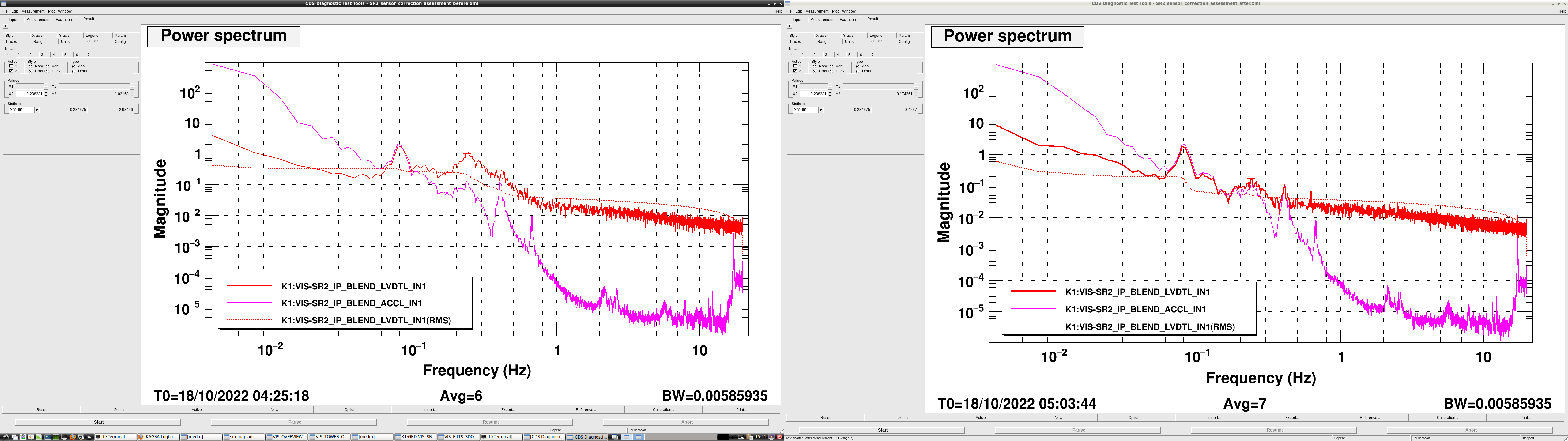
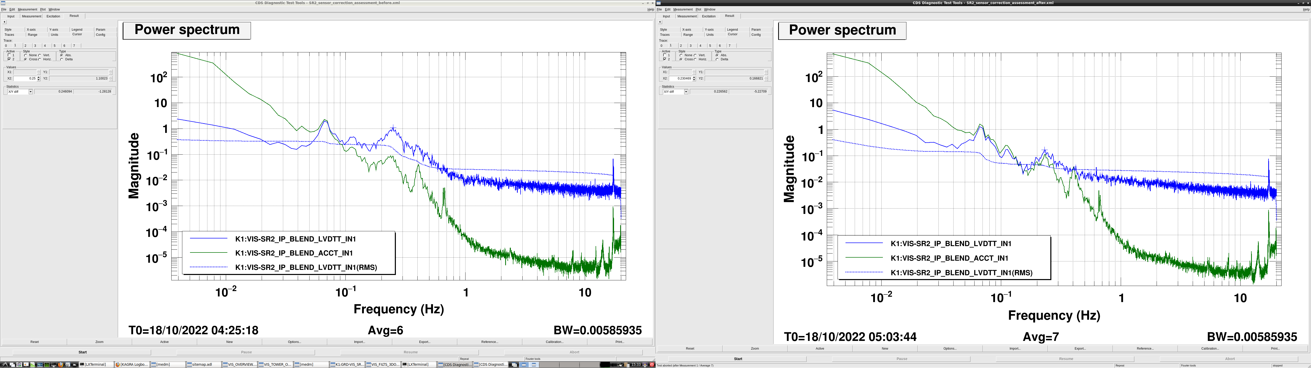
- See in Fig. 1 the ASD without (left) and with sensor correction (right).
- Reduction of the microseismic peak contribution: a factor of 5.8.
- LVDT-L and GEO-L at 238 mHz with the correction: 0.17 and 0.11 um/rtHz respectively.
- Integrated RMS down to 8 mHz, before and after correction: 0.34 um and 0.28 um.
Transverse
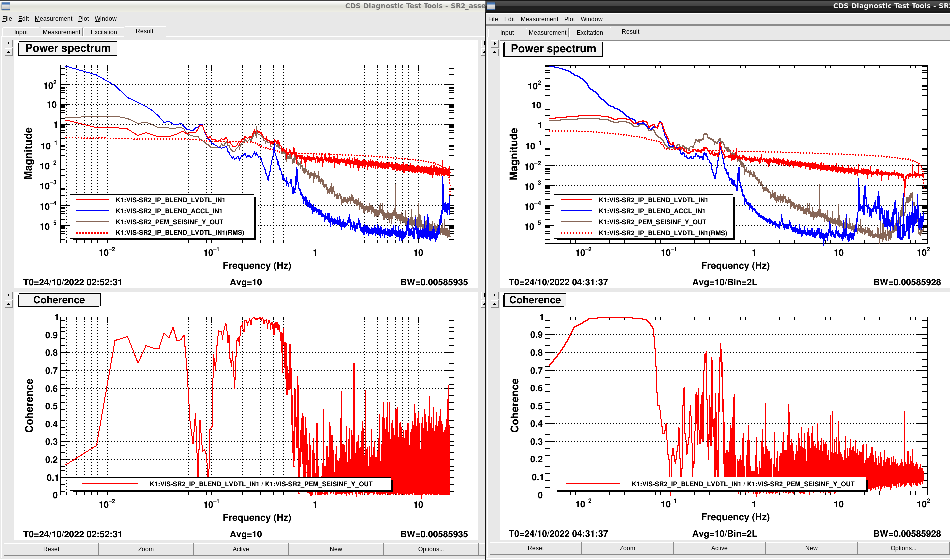
- See in Fig. 2 the ASD without (left) and with sensor correction (right).
- Reduction of the microseismic peak contribution: a factor of 6.6.
- LVDT-T and GEO-T at 250 mHz with the correction: 0.16 and 0.11 um/rtHz respectively
- Integrated RMS down to 8 mHz, before and after correction: 0.34 um and 0.23 um.
Comments
The sensor correction seems to be beneficial: it reduces the microseimic contribution in the LVDT readout by factors of 5.8 and 6.6 in L and T respectively, without (apparently) introducing low frequency noise harmful to the integrated RMS. It's worth pointing out that at the lowest frequency of the measurement (4 mHz), the ASD increases, increasing the integrated RMS. I didn't take this data point into account because its value is not reliable in the calculation of the FFT.
Despite the apparent success, the corrected LVDTs still don't measure the same as the geophones, suggesting that the sensor correction filter still can be improved.
Files are at
- Directory: /kagra/Dropbox/Subsystems/VIS/vis_commissioning/sr2/inter_calibration/
- File 1: SR2_sensor_correction_assessment_before.xml
- File 2: SR2_sensor_correction_assessment_after.xml
